Boost Pressure Control
Srinivasan; Prashant ; et al.
U.S. patent application number 16/245467 was filed with the patent office on 2019-08-08 for boost pressure control. The applicant listed for this patent is GE Jenbacher GmbH & Co. OG. Invention is credited to Chandan Kumar, Hang Lu, Karthikk R., Prashant Srinivasan.
| Application Number | 20190242297 16/245467 |
| Document ID | / |
| Family ID | 61187085 |
| Filed Date | 2019-08-08 |
| United States Patent Application | 20190242297 |
| Kind Code | A1 |
| Srinivasan; Prashant ; et al. | August 8, 2019 |
BOOST PRESSURE CONTROL
Abstract
An internal combustion engine is provided having at least one turbocharger having a compressor and an exhaust gas turbine, at least two actuating members for controlling a boost pressure by the compressor, a measuring device for measuring at least one measurement signal, and a control device adapted to actuate the actuating members by varying a degree of opening of the actuating members. The control device of the internal combustion engine is configured to calculate a total degree of opening of the actuating members necessary to achieve a desired boost pressure provided by the compressor. This is in dependence on the at least one measurement signal. The control device is also configured to determine the total degree of opening split between each of the at least two actuating members, and to control each of the actuating members according to its individual degree of opening to reach the desired boost pressure.
| Inventors: | Srinivasan; Prashant; (Bangalore, IN) ; Lu; Hang; (Freising, DE) ; Kumar; Chandan; (Bangalore, IN) ; R.; Karthikk; (Bangalore, IN) | ||||||||||
| Applicant: |
|
||||||||||
|---|---|---|---|---|---|---|---|---|---|---|---|
| Family ID: | 61187085 | ||||||||||
| Appl. No.: | 16/245467 | ||||||||||
| Filed: | January 11, 2019 |
| Current U.S. Class: | 1/1 |
| Current CPC Class: | F02B 37/18 20130101; F02B 37/16 20130101; F02D 41/0007 20130101; F02D 2200/101 20130101; F02D 2200/0406 20130101; F02D 29/06 20130101; F02B 37/22 20130101; F02B 37/162 20190501; Y02T 10/12 20130101; F02B 37/013 20130101 |
| International Class: | F02B 37/18 20060101 F02B037/18; F02B 37/16 20060101 F02B037/16; F02B 37/22 20060101 F02B037/22; F02B 37/013 20060101 F02B037/013 |
Foreign Application Data
| Date | Code | Application Number |
|---|---|---|
| Feb 6, 2018 | EP | 18155200.1 |
Claims
1. An internal combustion engine comprising: at least one turbocharger which has a compressor and an exhaust gas turbine; at least two actuating members for controlling a boost pressure provided by the compressor of the at least one turbocharger; a measuring device for measuring at least one measurement signal of the internal combustion engine; and a control device which is adapted to actuate the at least two actuating members by varying a degree of opening of the at least two actuating members; wherein the control device is configured to calculate a total degree of opening of the at least two actuating members necessary to achieve a desired boost pressure provided by the compressor in dependence on the measured at least one measurement signal, to determine how the total degree of opening is to be split between each of the at least two actuating members to obtain individual degrees of opening for each of the at least two actuating members, and to control each of the at least two actuating members according to its individual degree of opening so that the desired boost pressure provided by the compressor is reached.
2. The internal combustion engine according to claim 1, wherein the at least one measurement signal of the internal combustion engine is selected from an engine speed and a boost pressure.
3. The internal combustion engine according to claim 1, wherein the at least two actuating members are selected from the group consisting of a compressor bypass valve, a wastegate, and a throttle valve.
4. The internal combustion engine according to claim 1, wherein the control device is adapted to prevent attainment of a surge limit of the turbocharger.
5. The internal combustion engine according to claim 1, wherein there are provided two compressors.
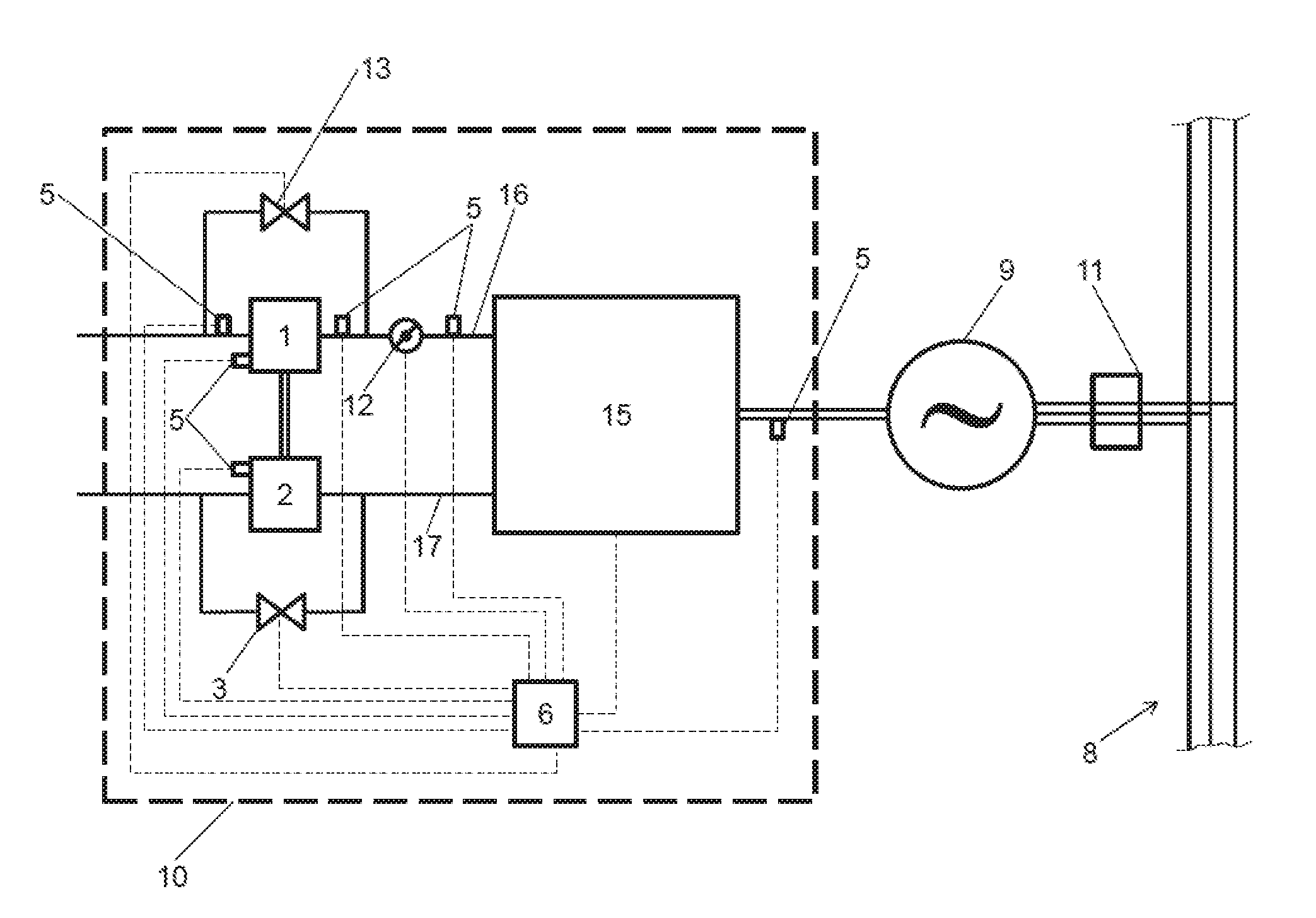
6. The internal combustion engine according to claim 1, wherein the control device attributes a weighting factor to each of the at least two actuating members and the total degree of opening is split between each of the at least two actuating members according to their weighting factors.
7. The internal combustion engine according to claim 6, wherein the control device is configured to adapt or re-adjust the weighting factors of the at least two actuating members during operation of the internal combustion engine.
8. The internal combustion engine according to claim 6, wherein the weighting factors of the at least two actuating members are pre-defined.
9. The internal combustion engine according to claim 1, wherein one of the at least two actuating members is a wastegate and one of the at least two actuating members is a compressor bypass valve.
10. The internal combustion engine according to claim 9, wherein a weighting factor of the wastegate is smaller than a pre-defined weighting factor of the bypass valve.
11. The internal combustion engine according to claim 9, wherein the control device is configured to close the compressor bypass valve in a stationary state of the internal combustion engine and to control boost pressure by the opening degree of the wastegate only.
12. The internal combustion engine according to claim 1, wherein the control device is configured to calculate the total degree of opening of the at least two actuating members in dependence on a compressor model.
13. A genset comprising a generator and an internal combustion engine according to claim 1, that is mechanically coupled to the generator.
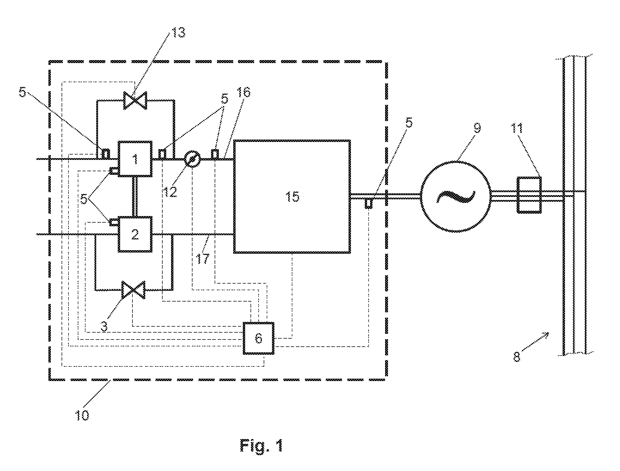
14. A method of operating an internal combustion engine comprising: providing at least one turbocharger which has a compressor and an exhaust gas turbine; providing at least two actuating members for controlling a boost pressure provided by the compressor of the at least one turbocharger; measuring at least one operating parameter of the internal combustion engine; calculating a total degree of opening of the at least two actuating members necessary to achieve a desired boost pressure provided by the compressor in dependence on the measured at least one operating parameter; determining the split of the total degree of opening between each of the at least two actuating members to obtain individual degrees of opening for each of the at least two actuating members; and opening each of the at least two actuating members according to a determined individual degree of opening so that the desired boost pressure provided by the compressor is reached.
Description
TECHNOLOGY FIELD
[0001] The present disclosure concerns an internal combustion engine with the features of the preamble of claim 1, a genset comprising such an internal combustion engine and a method of operating an internal combustion engine with the features of the preamble of claim 14.
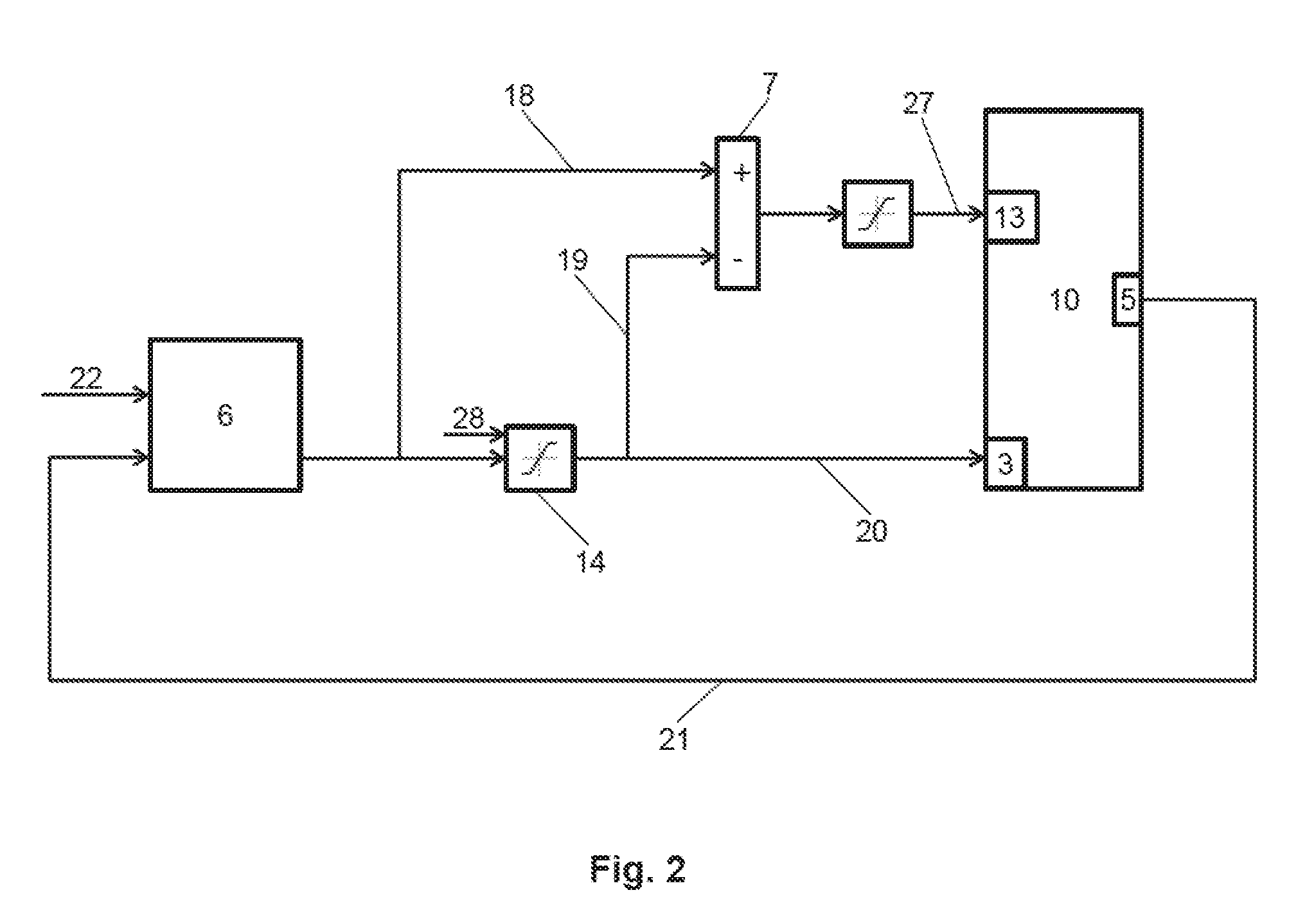
BACKGROUND OF THE DISCLOSURE
[0002] Turbochargers are used in order to boost pressure of air, a mixture of fuel and air or pure fuel before delivery to combustion chambers of the internal combustion engine.
[0003] An internal combustion engine with the features of the preamble of claim 1 is shown in U.S. Pat. No. 6,134,888.
BRIEF DESCRIPTION OF THE DISCLOSURE
[0004] The problem is to control the boost pressure in a turbocharged engine very fast during transients while avoiding surge and over-boost/turbo-over-speed. If one of the at least two actuating members is a compressor bypass valve it is preferred to have such a control strategy that the compressor bypass valve remains closed to the maximum extent possible during steady-state to maximize engine efficiency. Also, it is desirable that the control strategy is robust to failure, e. g. sticking of one of the at least two actuating members. This problem is solved by an internal combustion engine with the features of claim 1, by a genset having such an internal combustion engine and a method of operating an internal combustion engine with the features of claim 14. The embodiments of the present disclosure are defined in the dependent claims.
[0005] In transients, by using at least two of the at least two actuating members, the present disclosure enables very fast transient load acceptance and load rejection capability, a key requirement for users in new markets such as peaking and frequency regulation.
[0006] Also, the present disclosure makes it possible to have one of the at least two actuating members (the bypass valve) fully closed during steady-state, thus reducing pumping losses and maximizing engine efficiency.
[0007] The inventive control strategy is robust to sticking of one of the at least to actuating members in closed position since it can smoothly use the other actuating member for boost control and avoid over-boost or turbo over-speed.
[0008] The at least one measurement signal of the internal combustion engine can be selected from: [0009] an engine speed [0010] a boost pressure
[0011] The at least two actuating members can be selected from the group consisting of a compressor bypass valve, a wastegate or a throttle valve. A combination of one of the at least actuating members in form of a wastegate and one of the at least two actuating members in form of a bypass valve is preferred.
[0012] If there is an electrical booster, it is preferred to split the control signal of the control device between compressor bypass valve, wastegate and electrical booster.
[0013] Intake manifold pressure can be controlled by using a throttle valve.
[0014] It is preferred that the split of the total degree of opening between wastegate and compressor bypass valve is chosen in such a way that the wastegate gets the maximum share within its saturation limit.
[0015] Compression can be in the form of one compressor (one stage compression) or two compressors arranged in series (two stage compression). In the latter case, the compressor bypass can bypass both compressors (preferred) or only one of the compressors.
[0016] The control device can be adapted to prevent attainment of a surge limit of the turbocharger.
[0017] It can be provided that control device attributes a weighting factor to each of the at least two actuating members and the total degree of opening is split between each of the at least two actuating members according to their weighting factors.
[0018] For example, the control device can be configured to adapt or re-adjust the weighting factors of the at least two actuating members during operation to ensure optimal performance and fault tolerance in the event that failure of one or more actuators is diagnosed. Alternatively, it can be provided that the weighting factors of the at least two actuating members are pre-defined.
[0019] If a combination of one of the at least actuating members in form of a wastegate and one of the at least two actuating members in form of a compressor bypass valve is used, the weighting factor of the compressor bypass valve can be chosen smaller than the pre-defined weighting factor of the wastegate.
[0020] The control device is adapted to fully close the compressor bypass valve in a stationary state of the internal combustion engine and to control boost pressure by the opening degree of the wastegate only to improve efficiency of the internal combustion engine.
[0021] It can be provided that the control device is adapted by way of the at least one actuating member to cause a shift of the operating point on a predetermined path in the compressor mapping at least approximately parallel to the surge limit.
[0022] It can be provided that the control device is configured to calculate the total degree of opening of the at least two actuating members in dependence on a compressor model. Such a type of computation is being taught in various textbooks, e. g.: [0023] Hermann Hiereth, Peter Prenninger [0024] Aufladung der Verbrennungskraftmaschine--Der Fahrzeugantrieb/Chapter 5 2003 Springer--Verlag/Wien [0025] Gunther P. Merker, Rudiger Teichmann [0026] Grundlagen Verbrennungsmotoren (Funktionsweise--Simulation--Messtechnik)/Chapter 5 (Aufladesysteme), 7, vollstandig uberarbeitete Auflage 2014 Springer--Verlag/Wien [0027] Gunther P. Merker, Christian Schwarz [0028] Grundlagen Verbrennungsmotoren (Simulation der Gemischbildung, Verbrennung, Schadstoffbildung und Aufladung)/Chapter 8 (Aufladung von Verbrennungsmotoren) 4, uberarbeitete und aktualisierte Auflage Vieweg+Teubner, GWV Fachverlage GmbH, Wiesbaden 2009
[0029] The internal combustion engine is a reciprocating engine, in particular an engine driven by gaseous fuel.
BRIEF DESCRIPTION OF THE DRAWINGS
[0030] Embodiments of the present disclosure are shown in the figures.
[0031] FIG. 1 shows a schematic representation of an inventive internal combustion engine.
[0032] FIG. 2 shows an inventive internal combustion engine using a wastegate and a compressor bypass valve as actuating members.
[0033] FIG. 3 shows detail of the control device of FIG. 2.
DETAILED DESCRIPTION
[0034] FIG. 1 shows an internal combustion engine 10 having a plurality of combustion chambers 15 comprising a (single-stage) turbocharger which has a compressor 1 arranged in an intake manifold 16 and an exhaust gas turbine 2 arranged in an exhaust manifold 17. The compressor 1 can be bypassed using a bypass around the compressor 1. The extent of bypassing can be controlled depending on a degree of opening of a compressor bypass valve 13. The exhaust gas turbine 2 can be bypassed using a bypass around the exhaust gas turbine 2. The extent of bypassing can be controlled depending on a degree of opening of a wastegate 3.
[0035] The internal combustion engine 10 is in this embodiment part of a genset further comprising a generator 9 to which the internal combustion engine 10 is mechanically coupled. The generator 9 is coupled to a power supply network 8 having three phases. The connection to the power supply network 8 can be controlled by network switch 11.
[0036] The control device 6 is configured to receive information from measuring devices 5 (signal lines omitted) and send commands to a wastegate 3, a throttle valve 12 and a compressor bypass valve 13 (only the signal line leading to the wastegate 3 is shown).
[0037] The control device 6 is configured: [0038] to calculate a total degree of opening of the wastegate 3 and the compressor bypass valve 13 necessary to achieve a desired boost pressure provided by the compressor 1 in dependence on at least one measured operating parameter [0039] to determine how the total degree of opening is to be split between wastegate 3 and compressor bypass valve 13 to obtain individual degrees of opening for each of them [0040] to control the wastegate 3 and the compressor bypass valve 13 according to its individual degree of opening so that the desired boost pressure provided by the compressor is reached
[0041] Furthermore, the control device 6 is configured to fully close the compressor bypass valve 13 in a stationary state of the internal combustion engine 10 and to control boost pressure by the opening degree of the wastegate 3 only.
[0042] An embodiment of the control strategy of the present disclosure using feedback (in this case boost pressure) from the measuring device 5 is shown in FIG. 2. The closed-loop control device 6 receives actual boost pressure from measuring device 5 via signal line 21 and compares actual boost pressure to a desired boost setpoint provided via signal line 22. The wastegate 3 is used as primary actuator and is commanded to adjust degree of opening. The rest of the degree of opening necessary to reach the desired boost pressure is being provided by the compressor bypass valve 13.
[0043] Control device 6 outputs three output signals: a lower limit as input for a saturation block 14 (this is usually a fixed limit, e. g. zero), an upper limit as input for the saturation block 14 (which is being changed in realtime, cf. FIG. 3) and a control signal as input for the saturation block 14 and an adding block 7 (via signal line 19).
[0044] If, e. g., the control signal represents 80% degree of opening for the wastegate 3 this control signal is sent to adding block 7 via signal line 18. This control signal is also sent to saturation block 14. If, e. g. the lower limit is zero and the upper limit is 60%, the output of saturation block 14 to the wastegate 3 via signal line 20 will be 60% degree of opening. The output of adding block 7 will be 20% (=80%-20%) degree of opening for the compressor bypass valve 13. If, however the control signal represents 55% degree of opening for the wastegate 3 (i.e. below the upper limit of the saturation block 14), this signal will be input to the wastegate 3 and the degree of opening of the wastegate 3 will be 55%. The control signal for the compressor bypass valve 13 via command line 27 will amount to 0% (=55%-55%) degree of opening (closed compressor bypass valve 13).
[0045] In other words, as long as the required degree of opening of the wastegate 3 is below the upper limit of saturation block 14 the wastegate 3 will be opened to that degree and the compressor bypass valve 13 will be closed.
[0046] A way of determining the upper limit of the saturation block 14 in real-time is shown in FIG. 3. The structure of FIG. 3 can form part of control device 6.
[0047] The measurement devices 5 which are arranged before and after the compressor 1 provide pressure before and after compressor 1. An actual ratio of pressure after compressor 1 to pressure before compressor 1 is being calculated and provided to block 25 via signal line 24. This block 25 also receives as input via signal line 23 a maximally allowed pressure ratio (which can vary). Block 25 divides the maximal allowed pressure ratio by the actual pressure ratio and inputs this number to a look-up table 4 (alternatively an algorithm could be used). The look-up table 4 checks whether the input number is large enough in the sense that surge margin is large enough. If this is the case, the upper limit for saturation block 14 will be set to 100% (i. e. no limitation on degree of opening of wastegate 3). If this is not the case, the upper limit will be set to an appropriate number given by the look-up table 4.
[0048] E. g., suppose maximal allowed pressure ratio is 5 and actual pressure ratio is 2. In this case, the input for the look-up table 4 will be 2.5 which is considered to be safe by the look-up table 4. In this case the upper limit for saturation block 14 will be set to 100%. If, however, the actual pressure ratio is 4, the ratio is 1.25 and the look-up table 4 will determine that the resulting surge margin is too small. In this case, the upper limit for the wastegate 3 will, e. g. be set to be 60% degree of opening.
[0049] In other words, in this embodiment, maximum waste-gate degree of opening is a function of the ratio of maximum allowed pressure ratio and actual pressure ratio which is indicative of the remaining surge margin.
[0050] The maximum allowed pressure ratio can be determined by a model-based dynamic mass flow calculation.
[0051] There is also provided a low pass filter 26 with a chosen time constant (e. g. 0.1 seconds) to avoid fast oscillations.
* * * * *
D00000
D00001
D00002
D00003
XML
uspto.report is an independent third-party trademark research tool that is not affiliated, endorsed, or sponsored by the United States Patent and Trademark Office (USPTO) or any other governmental organization. The information provided by uspto.report is based on publicly available data at the time of writing and is intended for informational purposes only.
While we strive to provide accurate and up-to-date information, we do not guarantee the accuracy, completeness, reliability, or suitability of the information displayed on this site. The use of this site is at your own risk. Any reliance you place on such information is therefore strictly at your own risk.
All official trademark data, including owner information, should be verified by visiting the official USPTO website at www.uspto.gov. This site is not intended to replace professional legal advice and should not be used as a substitute for consulting with a legal professional who is knowledgeable about trademark law.