Hydraulic Lash Adjuster Assembly Sleeves
Brown; Leon ; et al.
U.S. patent application number 16/386437 was filed with the patent office on 2019-08-08 for hydraulic lash adjuster assembly sleeves. This patent application is currently assigned to Eaton Intelligent Power Limited. The applicant listed for this patent is Eaton Intelligent Power Limited. Invention is credited to Leon Brown, James E. McCarthy, JR..
| Application Number | 20190242276 16/386437 |
| Document ID | / |
| Family ID | 62019282 |
| Filed Date | 2019-08-08 |


| United States Patent Application | 20190242276 |
| Kind Code | A1 |
| Brown; Leon ; et al. | August 8, 2019 |
HYDRAULIC LASH ADJUSTER ASSEMBLY SLEEVES
Abstract
A hydraulic lash adjuster (HLA) sleeve configured to be received within a lifter bore of an engine block, includes a cylindrical sleeve having an outer surface defining an outer diameter, and an inner surface defining an inner diameter. The outer diameter is sized for an interference fit with the lifter bore to prevent rotation of the HLA sleeve within the lifter bore. The inner diameter is sized to receive a lifter.
| Inventors: | Brown; Leon; (Pontiac, MI) ; McCarthy, JR.; James E.; (Kalamazoo, MI) | ||||||||||
| Applicant: |
|
||||||||||
|---|---|---|---|---|---|---|---|---|---|---|---|
| Assignee: | Eaton Intelligent Power
Limited Dublin IE |
||||||||||
| Family ID: | 62019282 | ||||||||||
| Appl. No.: | 16/386437 | ||||||||||
| Filed: | April 17, 2019 |
Related U.S. Patent Documents
| Application Number | Filing Date | Patent Number | ||
|---|---|---|---|---|
| PCT/US2017/056842 | Oct 17, 2017 | |||
| 16386437 | ||||
| 62409084 | Oct 17, 2016 | |||
| Current U.S. Class: | 1/1 |
| Current CPC Class: | F01L 2001/256 20130101; F01L 2001/2427 20130101; F01L 2820/01 20130101; F01L 1/24 20130101; F01L 2305/00 20200501; F01L 1/146 20130101; F01L 2307/00 20200501 |
| International Class: | F01L 1/24 20060101 F01L001/24; F01L 1/14 20060101 F01L001/14 |
Claims
1. A hydraulic lash adjuster (HLA) sleeve configured to be received within a lifter bore of an engine block, the HLA sleeve comprising: a cylindrical sleeve having an outer surface defining an outer diameter, and an inner surface defining an inner diameter; wherein the outer diameter is sized for an interference fit with the lifter bore to prevent rotation of the HLA sleeve within the lifter bore; and wherein the inner diameter is sized to receive a lifter.
2. The HLA sleeve of claim 1, wherein the inner surface includes a first flat configured to engage a second flat formed on the lifter to prevent rotation of the lifter within the HLA sleeve.
3. The HLA sleeve of claim 1, further comprising an outer key extending outwardly from the outer surface, the outer key configured to be received by the engine block to prevent rotation of the HLA sleeve within the lifter bore.
4. The HLA sleeve of claim 3, wherein the inner surface includes a flat.
5. The HLA sleeve of claim 3, further comprising an inner key extending inwardly from the inner surface, the inner key configured to be received by the lifter to prevent relative rotation of the lifter within the HLA sleeve.
6. The HLA sleeve of claim 1, further comprising an inner key extending inwardly from the inner surface, the inner key configured to be received by the lifter to prevent relative rotation of the lifter within the HLA sleeve.
7. The HLA sleeve of claim 1, further comprising a hydraulic fluid port formed through the cylindrical sleeve and configured to supply hydraulic fluid to the lifter.
8. The HLA sleeve of claim 7, further comprising an annular groove formed in the inner surface and in fluid communication with the hydraulic fluid port, the annular groove configured to supply hydraulic fluid to the lifter.
9. A set of hydraulic lash adjuster (HLA) sleeves configured to be received within a lifter bore of an engine block, the set of HLA sleeves comprising: a first cylindrical sleeve having an outer surface defining a first outer diameter, and an inner surface defining a first inner diameter; a second cylindrical sleeve having an outer surface defining a second outer diameter, and an inner surface defining a second inner diameter; and wherein the first outer diameter is larger than the second outer diameter, wherein one of the first and second cylindrical sleeves is configured to be chosen from the set of HLA sleeves to fit into a corresponding sized lifter bore, and wherein the first and second inner diameters are equal and are each configured to receive a same lifter.
10. The set of HLA sleeves of claim 9, further comprising a third cylindrical sleeve having an outer surface defining a third outer diameter, and an inner surface defining a third inner diameter, wherein the second outer diameter is larger than the third outer diameter, wherein one of the first, second, and third cylindrical sleeves is configured to be chosen from the set of HLA sleeves to fit into a corresponding sized lifter bore, wherein the first, second, and third inner diameters are equal and are each configured to receive a same lifter.
11. The set of HLA sleeves of claim 9, wherein the inner surface of the first and second cylindrical sleeves includes a first flat configured to engage a second flat formed on the same lifter to prevent rotation of the same lifter within the first and second cylindrical sleeves.
12. The set of HLA sleeves of claim 9, further comprising an outer key extending outwardly from the outer surface of each of the first and second cylindrical sleeves, the outer key configured to be received by the engine block to prevent rotation of the first or second cylindrical sleeves within the lifter bore.
13. The set of HLA sleeves of claim 12, wherein the inner surface of the first and second cylindrical sleeves includes a flat.
14. The set of HLA sleeves of claim 12, further comprising an inner key extending inwardly from the inner surface of each of the first and second cylindrical sleeves, the inner key configured to be received by the same lifter to prevent relative rotation of the same lifter within the first and second cylindrical sleeves.
15. The set of HLA sleeves of claim 9, further comprising an inner key extending inwardly from the inner surface of each of the first and second cylindrical sleeves, the inner key configured to be received by the same lifter to prevent relative rotation of the same lifter within the HLA sleeve.
16. The set of HLA sleeves of claim 9, further comprising a hydraulic fluid port formed through each of the first and second cylindrical sleeves and configured to supply hydraulic fluid to the same lifter.
17. The set of HLA sleeves of claim 16, further comprising an annular groove formed in the inner surface of each of the first and second cylindrical sleeves, the annular groove in fluid communication with the hydraulic fluid port, the annular groove configured to supply hydraulic fluid to the same lifter.
18. A hydraulic lash adjuster (HLA) assembly configured to be received within a lifter bore of an engine block, the HLA assembly comprising: a cylindrical HLA sleeve having an outer surface defining an outer diameter, and an inner surface defining an inner diameter, wherein the outer diameter is sized for an interference fit with the lifter bore to prevent rotation of the HLA sleeve within the lifter bore; and a lifter disposed within the HLA sleeve, the HLA sleeve enabling the lifter with a diameter smaller than a diameter of the lifter bore to be operably disposed therein.
19. The HLA assembly of claim 18, wherein the HLA sleeve is configured to be press-fit into the lifter bore to facilitate preventing rotation of the HLA sleeve within the lifter bore.
20. The HLA assembly of claim 18, wherein the lifter includes a roller configured to interface with a cam and a flat that interfaces with a cam which can rotate within the cylindrical HLA sleeve.
Description
CROSS-REFERENCE TO RELATED APPLICATION
[0001] This application is a continuation of International Application No. PCT/US2017/056842 filed Oct. 17, 2017, which claims the benefit of U.S. Provisional Application No. 62/409,084, filed Oct. 17, 2016, the contents of which are incorporated herein by reference thereto.
FIELD
[0002] The present disclosure relates to a hydraulic lash adjuster assembly and, more particularly, to a set of sleeves that enable a hydraulic lash adjuster assembly to be used in multiple engine applications.
BACKGROUND
[0003] Some internal combustion engines can utilize rocker arms to transfer rotational motion of cams to linear motion appropriate for opening and closing engine valves. Deactivating rocker arms can incorporate hydraulic lash adjuster (HLA) mechanisms into a lifter bore of an engine block that allow for selective activation and deactivation of the rocker arm. However, the size of the lifter bores for the HLA mechanisms can vary across different types of engines, thus requiring specially sized HLA mechanisms for each size of lifter bore.
[0004] The background description provided herein is for the purpose of generally presenting the context of the disclosure. Work of the presently named inventors, to the extent it is described in this background section, as well as aspects of the description that may not otherwise qualify as prior art at the time of filing, are neither expressly nor impliedly admitted as prior art against the present disclosure.
SUMMARY
[0005] In one aspect of the present disclosure, a hydraulic lash adjuster (HLA) sleeve configured to be received within a lifter bore of an engine block is provided. The HLA sleeve includes a cylindrical sleeve having an outer surface defining an outer diameter, and an inner surface defining an inner diameter. The outer diameter is sized for an interference fit with the lifter bore to prevent rotation of the HLA sleeve within the lifter bore, and the inner diameter is sized to receive a lifter.
[0006] In addition to the foregoing, the described HLA sleeve may include one or more of the following features: wherein the inner surface includes a first flat configured to engage a second flat formed on the lifter to prevent rotation of the lifter within the HLA sleeve; an outer key extending outwardly from the outer surface, the outer key configured to be received by the engine block to prevent rotation of the HLA sleeve within the lifter bore; wherein the inner surface includes a flat; an inner key extending inwardly from the inner surface, the inner key configured to be received by the lifter to prevent relative rotation of the lifter within the HLA sleeve; an inner key extending inwardly from the inner surface, the inner key configured to be received by the lifter to prevent relative rotation of the lifter within the HLA sleeve; a hydraulic fluid port formed through the cylindrical sleeve and configured to supply hydraulic fluid to the lifter; and an annular groove formed in the inner surface and in fluid communication with the hydraulic fluid port, the annular groove configured to supply hydraulic fluid to the lifter.
[0007] In another aspect of the present disclosure, a set of hydraulic lash adjuster (HLA) sleeves configured to be received within a lifter bore of an engine block is provided. The set of HLA sleeves includes a first cylindrical sleeve having an outer surface defining a first outer diameter, and an inner surface defining a first inner diameter, and a second cylindrical sleeve having an outer surface defining a second outer diameter, and an inner surface defining a second inner diameter. The first outer diameter is larger than the second outer diameter. One of the first and second cylindrical sleeves is configured to be chosen from the set of HLA sleeves to fit into a corresponding sized lifter bore, and the first and second inner diameters are equal and are each configured to receive a same lifter.
[0008] In addition to the foregoing, the described set of HLA sleeves may include one or more of the following features: a third cylindrical sleeve having an outer surface defining a third outer diameter, and an inner surface defining a third inner diameter, wherein the second outer diameter is larger than the third outer diameter, wherein one of the first, second, and third cylindrical sleeves is configured to be chosen from the set of HLA sleeves to fit into a corresponding sized lifter bore, and wherein the first, second, and third inner diameters are equal and are each configured to receive a same lifter.
[0009] In addition to the foregoing, the described set of HLA sleeves may include one or more of the following features: wherein the inner surface of the first and second cylindrical sleeves includes a first flat configured to engage a second flat formed on the same lifter to prevent rotation of the same lifter within the first and second cylindrical sleeves; an outer key extending outwardly from the outer surface of each of the first and second cylindrical sleeves, the outer key configured to be received by the engine block to prevent rotation of the first or second cylindrical sleeves within the lifter bore; wherein the inner surface of the first and second cylindrical sleeves includes a flat; and an inner key extending inwardly from the inner surface of each of the first and second cylindrical sleeves, the inner key configured to be received by the same lifter to prevent relative rotation of the same lifter within the first and second cylindrical sleeves.
[0010] In addition to the foregoing, the described set of HLA sleeves may include one or more of the following features: an inner key extending inwardly from the inner surface of each of the first and second cylindrical sleeves, the inner key configured to be received by the same lifter to prevent relative rotation of the same lifter within the HLA sleeve; a hydraulic fluid port formed through each of the first and second cylindrical sleeves and configured to supply hydraulic fluid to the same lifter; and an annular groove formed in the inner surface of each of the first and second cylindrical sleeves, the annular groove in fluid communication with the hydraulic fluid port, the annular groove configured to supply hydraulic fluid to the same lifter.
[0011] In yet another aspect of the present disclosure, a hydraulic lash adjuster (HLA) assembly is provided. The HLA assembly is configured to be received within a lifter bore of an engine block, and includes a cylindrical HLA sleeve and a lifter. The cylindrical HLA sleeve includes an outer surface defining an outer diameter, and an inner surface defining an inner diameter. The outer diameter is sized for an interference fit with the lifter bore to prevent rotation of the HLA sleeve within the lifter bore. The lifter is disposed within the HLA sleeve, the HLA sleeve enabling the lifter with a diameter smaller than a diameter of the lifter bore to be operably disposed therein.
[0012] In addition to the foregoing, the described HLA assembly may include one or more of the following features: wherein the HLA sleeve is configured to be press-fit into the lifter bore to facilitate preventing rotation of the HLA sleeve within the lifter bore; wherein the lifter includes a roller configured to interface with a cam; and wherein the lifter includes a flat that interfaces with a cam which can rotate within the cylindrical HLA sleeve.
[0013] In yet another aspect of the present disclosure, a method of assembling an internal combustion engine having a wall defining an oversized lifter bore is provided. The method includes providing a lifter having a diameter smaller than a diameter of the oversized lifter bore, determining a size of the oversized lifter bore, and selecting a hydraulic lash adjuster (HLA) sleeve to take up annular space between the lifter and the wall defining the oversized lifter bore to thereby secure the lifter within the oversized lifter bore.
[0014] In addition to the foregoing, the described method may include one or more of the following features: inserting the HLA sleeve into the oversized lifter bore; and inserting the lifter into the HLA sleeve.
BRIEF DESCRIPTION OF THE DRAWINGS
[0015] The present disclosure will become more fully understood from the detailed description and the accompanying drawings, wherein:
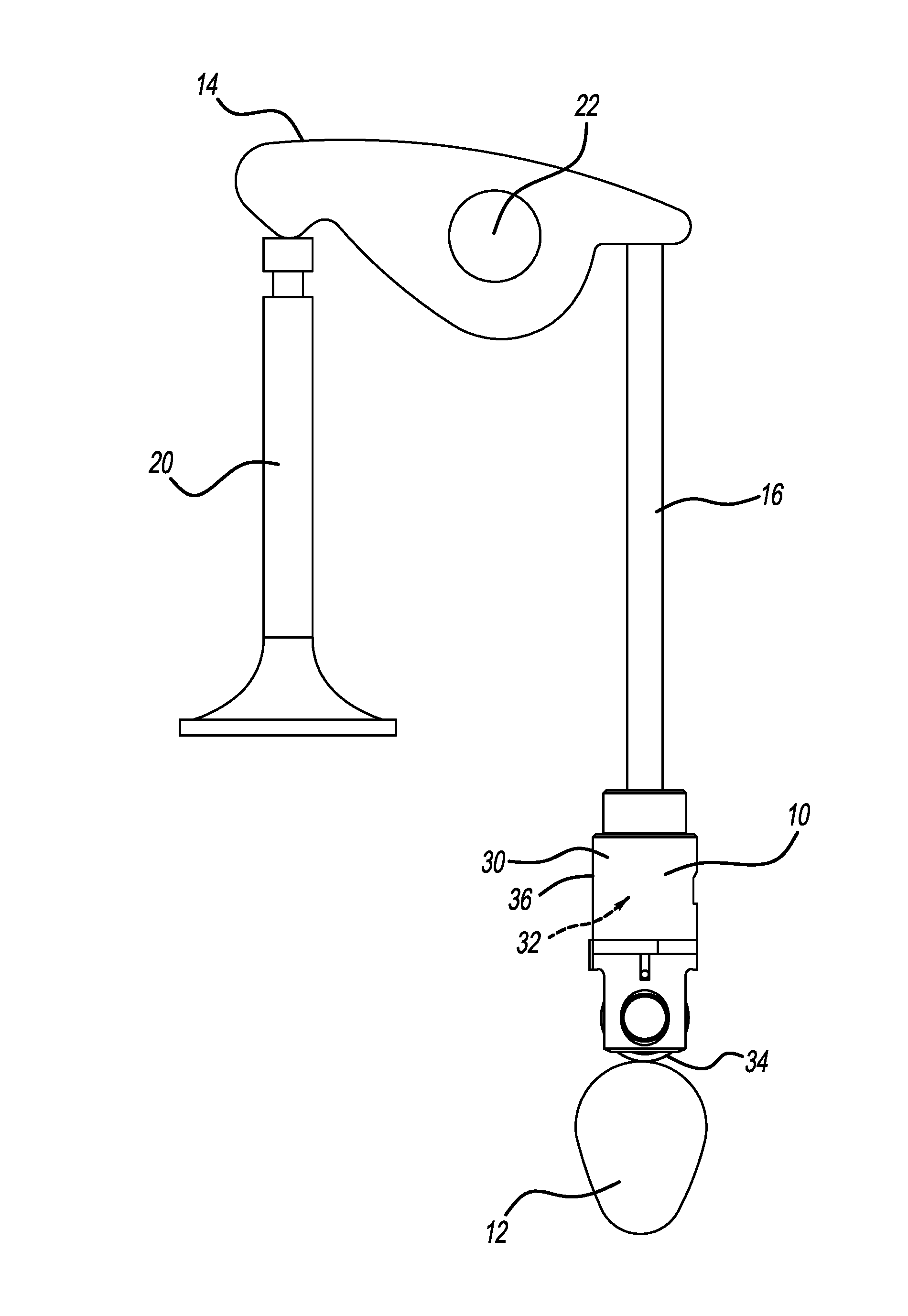
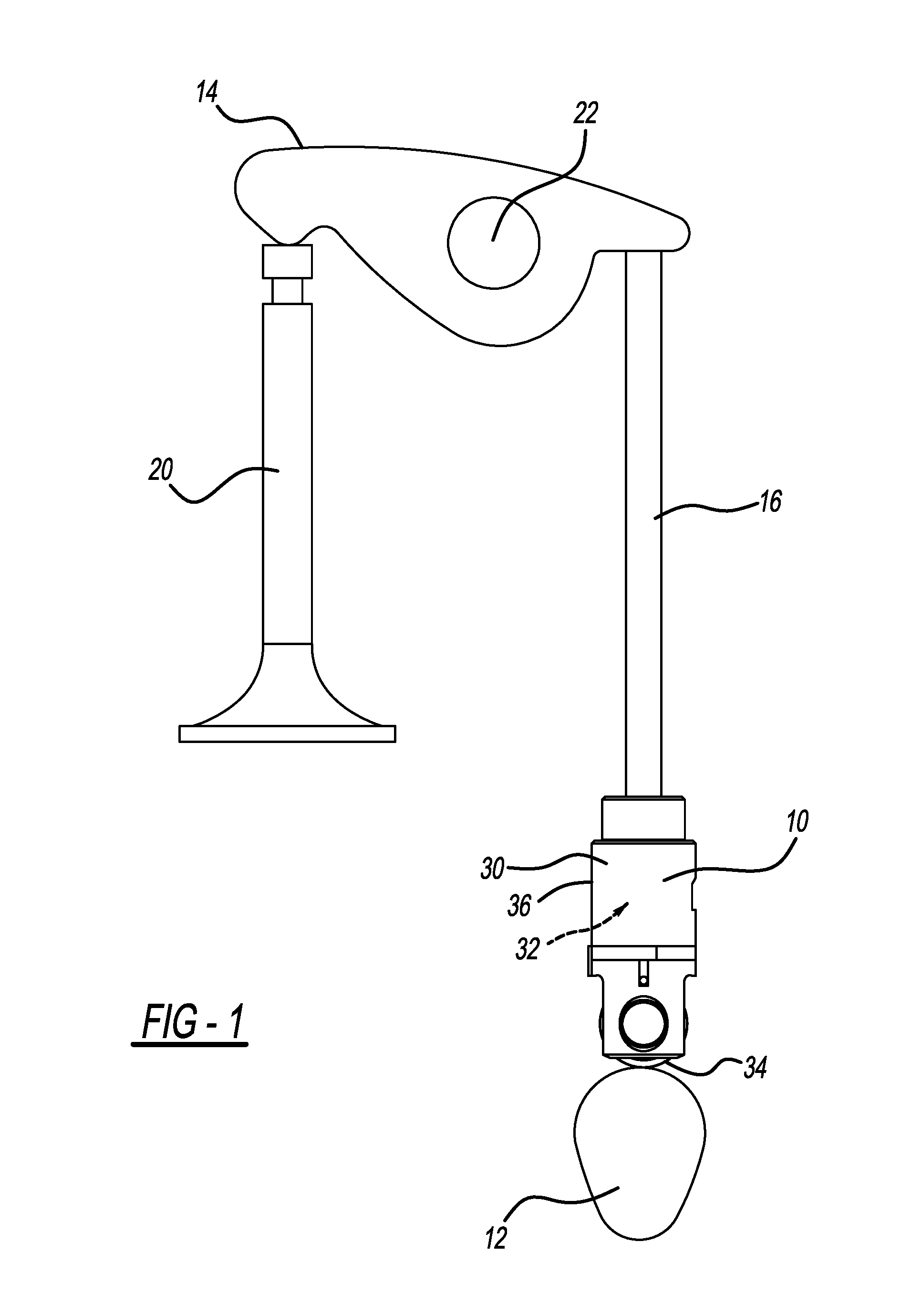
[0016] FIG. 1 is a roller lifter constructed in accordance to one example of the present disclosure and shown in an exemplary Type V valve train arrangement;
[0017] FIG. 2A is a roller lifter constructed in accordance to one example of the present disclosure;
[0018] FIG. 2B is a cross-sectional view of an exemplary hydraulic lash adjuster (HLA) sleeve constructed in accordance to one example of the present disclosure and shown received in an exemplary engine block;
[0019] FIG. 2C is a top view of the HLA sleeve of FIG. 2B;
[0020] FIG. 3 is a cross-sectional view of a valve train arrangement having the HLA sleeve shown in FIG. 1, in accordance to one example of the present disclosure;
[0021] FIG. 4 illustrates a set of HLA sleeves in accordance to one example of the present disclosure; and
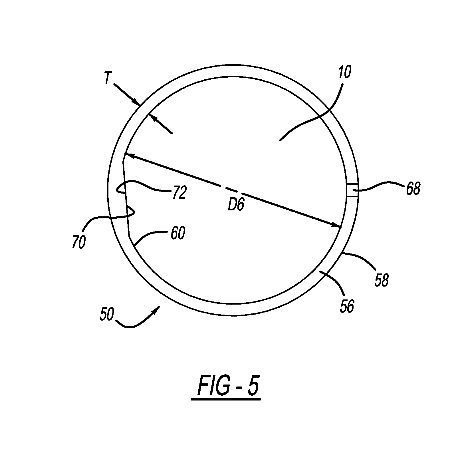
[0022] FIG. 5 is a top view of an HLA sleeve and lifter in accordance to one example of the present disclosure.
DETAILED DESCRIPTION
[0023] With initial reference to FIG. 1, a hydraulic lash adjuster (HLA) roller lifter constructed in accordance to one example of the present disclosure is shown and generally identified at reference number 10. Roller lifter 10 is shown as part of a Type V valve train arrangement. However, it will be appreciated that while shown in a Type V arrangement, it is within the scope of the present disclosure for the various features described herein to be used in other arrangements. In this regard, the features described herein associated with the valve train arrangement 10 can be suitable to a wide variety of applications. A cam lobe 12 indirectly drives a first end of a rocker arm 14 with a push rod 16. It will be appreciated that in some configurations, such as an overhead cam, the roller lifter may be a direct link between the cam lobe 12 and the rocker arm 14. A second end of the rocker arm 14 actuates a valve 20. As the cam lobe 12 rotates, the rocker arm 14 pivots about a fixed shaft 22.
[0024] In the example implementation, the roller lifter 10 generally includes a body 30, a leakdown assembly 32 received within the body 30, and a roller bearing 34 rotatably mounted to the body 30. The body 30 includes an outer peripheral surface 36 configured for sliding movement in a lifter bore 40 provided in a cylinder head or engine block 42 of an internal combustion engine 44 (see FIG. 2B). As shown in FIGS. 2 and 3, roller lifter 10 is configured to be disposed within an HLA sleeve 50, which is configured for insertion into the lifter bore 40 formed in the engine block 42. In this way, HLA sleeve 50 can take up the annular space between roller lifter 10 and an oversized bore 40.
[0025] Moreover, as shown in FIG. 4, HLA sleeve 50 may be part of a set 100 of HLA sleeves 50, 50', 50'' each having the same inner diameter D6 to receive HLA roller lifter 10, but having different outer diameters (e.g., D1, D1', D1''). As illustrated, D1 is greater than D1', which is greater than D1''. This enables the same roller lifter 10 to be installed into lifter bores (e.g., 40, 40', 40'') having various diameters by selecting from the different sized HLA sleeves 50. As illustrated, the diameter of bore 40 is greater than the diameter of bore 40', which is greater than the diameter of bore 40''. As such, a new roller lifter does not need to be designed and sized for each of the various sized lifter bores 40 that occur across multiple engine platforms.
[0026] As illustrated in FIGS. 2A-2C, each HLA sleeve 50 includes a cylindrical or generally cylindrical wall or sleeve 56 having a thickness `T`, an outer surface 58 defining outer diameter D1 (FIG. 2B), and an inner surface 60 defining inner diameter D6. Inner surface 60 defines a receiving aperture 62 to receive HLA roller lifter 10. Thickness `T` is defined such that outer diameter D1 is equal to or slightly larger than a diameter of bore 40, thereby ensuring an interference fit between HLA sleeve 50 and lifter bore 40 to facilitate preventing rotation of HLA sleeve 50 within lifter bore 40. As such, an HLA sleeve 50 is selected with dimensions to take up the size difference between the lifter bore 40 and the roller lifter 10.
[0027] In one arrangement shown in FIGS. 2A-2C, HLA sleeve 50 can include an outer key 64 and an inner key 66. Outer key 64 is configured to be received within a slot (not shown) formed within lifter bore 40 to thereby prevent rotation of HLA sleeve 50 within lifter bore 40. As shown in FIG. 2C, outer key 64 can have a width D5 and a depth D7. Inner key 66 is configured to be received within a slot 67 formed in roller lifter 10 to thereby prevent rotation of roller lifter 10 within HLA sleeve 50. As shown in FIGS. 2A-2C, inner key 66 can have a height D2, a width D3, and a depth D4, and roller lifter slot 67 can have a width D8. In one example, width D8 is equal to or slightly larger than width D3.
[0028] In alternative arrangements, rather than having keys 64, 66, HLA sleeve 50 may be press-fit into bore 40 and can include an inner flat 70 (e.g., a flat surface) formed on inner surface 60 (see FIG. 5). The inner flat 70 is configured to engage a lifter flat 72 (e.g., a flat surface formed on lifter 10 to thereby prevent rotation of lifter 10 within HLA sleeve 50. This enables HLA sleeve 50 to prevent rotation of lifter 10 without having to alter the round lifter bore 40 (e.g., forming shapes or flats in the bore 40). Moreover, sleeve outer surface 58 may be formed with a rough texture to facilitate gripping the wall of lifter bore 40 and preventing rotation of HLA sleeve 50.
[0029] In other examples, HLA sleeve 50 and/or roller lifter 10 may have other complementary shapes or geometries configured to prevent rotation of roller lifter 10 within HLA sleeve (e.g., spheres, slots, etc.). In this regard, the HLA sleeve 50 may have a first engaging structure therein (such as on an inner surface) and the roller lifter 10 may have a complementary second engaging structure thereon (such as on an outer surface) for mating with the first engaging structure. The first and second engaging structures can be keyed or mated to inhibit or preclude relative rotation of the roller lifter 10 within the HLA sleeve 50. The first and second engaging structures can comprise any suitable complementary geometries such as concave depressions and convex extensions, slots and grooves, and other configurations.
[0030] One example method of assembling an internal combustion engine 44 includes providing an engine block 42 with at least one oversized bore 40. An HLA roller lifter 10 is provided having a predetermined diameter `D` that is smaller than the diameter of the oversized bore. The size of bore 40 is determined, and one HLA sleeve 50 is selected from a set of HLA sleeves to take up the annular space between the roller lifter 10 and the wall defining lifter bore 40. The selected HLA sleeve 50 is chosen having an outer diameter D1 equal to or slightly greater than the diameter of the lifter bore 40. The HLA sleeve 50 is inserted (e.g., press-fit) into lifter bore 40, and roller lifter 10 is subsequently inserted into the selected HLA sleeve 50. Alternatively, roller lifter 10 may be inserted into HLA sleeve 50, and sleeve 50 is subsequently inserted into lifter bore 40.
[0031] In one implementation, HLA sleeve 50 is fabricated with an interference fit with lifter bore 40 of 0.0025'' or approximately 0.0025'' when engine block 42 is fabricated from cast iron. In another implementation, HLA sleeve 50 is fabricated with an interference fit with bore 40 of 0.004'' or approximately 0.004'' when engine block 42 is fabricated from aluminum.
[0032] In one implementation, the HLA sleeve set includes three HLA sleeves 50 having thicknesses `T` of 1/16'', 3/32'', and 1/8''. In other implementations, the thicknesses `T` are approximately 1/16'', approximately 3/32'', and approximately 1/8''. Accordingly, this enables one HLA sleeve 50 of the set of sleeves 100 to fit within various sized lifter bores 40 of varied engines 44 while maintaining the strength of the engine blocks 42. In one implementation, roller lifter 10 has a diameter of between 24 mm and 40 mm or between approximately 24 mm and approximately 40 mm. In another implementation, roller lifter 10 has a diameter of between 26 mm and 32 mm or between approximately 26 mm and approximately 32 mm. However, it will be appreciated that thickness `T`, outer diameter D1, inner diameter D6 may have any suitable size to accommodate various sized roller lifters 10 and lifter bores 40.
[0033] Moreover, HLA sleeve 50 may include one or more oil channel or feed 68 (FIG. 2) configured to supply oil or other hydraulic fluid from a source to the roller lifter 10. Additionally, as shown in FIG. 3, sleeve inner surface 60 may include an annular groove 74 formed therein and in fluid communication with the hydraulic fluid feed 68. The annular groove 74 can be configured to supply hydraulic fluid to the lifter 10 via a groove 76, and can extend around the entirety or only a portion of the circumference of sleeve inner surface 60.
[0034] In some examples, HLA sleeve 50 is fabricated from a centrifugally spun cast iron alloy of carbon-chrome and molybdenum featuring high tensile strength of 48,000 psi to 53,000 psi. Alternatively, HLA sleeve 50 may be fabricated from plastic, ductile iron, HSS steel stamping, hydroformed tubing, or any other suitable material/process that enables HLA sleeve 50 to function as described herein.
[0035] The foregoing description of the examples has been provided for purposes of illustration and description. It is not intended to be exhaustive or to limit the disclosure. Individual elements or features of a particular example are generally not limited to that particular example, but, where applicable, are interchangeable and can be used in a selected example, even if not specifically shown or described. The same may also be varied in many ways. Such variations are not to be regarded as a departure from the disclosure, and all such modifications are intended to be included within the scope of the disclosure.
* * * * *
D00000
D00001
D00002
D00003
D00004
D00005
XML
uspto.report is an independent third-party trademark research tool that is not affiliated, endorsed, or sponsored by the United States Patent and Trademark Office (USPTO) or any other governmental organization. The information provided by uspto.report is based on publicly available data at the time of writing and is intended for informational purposes only.
While we strive to provide accurate and up-to-date information, we do not guarantee the accuracy, completeness, reliability, or suitability of the information displayed on this site. The use of this site is at your own risk. Any reliance you place on such information is therefore strictly at your own risk.
All official trademark data, including owner information, should be verified by visiting the official USPTO website at www.uspto.gov. This site is not intended to replace professional legal advice and should not be used as a substitute for consulting with a legal professional who is knowledgeable about trademark law.