Spacer Braces For Walls, Joists & Trusses
LeBlang; Dennis
U.S. patent application number 14/946378 was filed with the patent office on 2019-08-08 for spacer braces for walls, joists & trusses. The applicant listed for this patent is Dennis LeBlang. Invention is credited to Dennis LeBlang.
| Application Number | 20190242112 14/946378 |
| Document ID | / |
| Family ID | 67475422 |
| Filed Date | 2019-08-08 |


View All Diagrams
| United States Patent Application | 20190242112 |
| Kind Code | A1 |
| LeBlang; Dennis | August 8, 2019 |
SPACER BRACES FOR WALLS, JOISTS & TRUSSES
Abstract
The present invention relates to using interlocking spacer braces between support members to construct wood and metal framed walls, floors and building trusses. Spacer braces have indentations, extensions, fingers that interlock horizontally, vertically or diagonally between support members. The spacer braces can form diagonal and lateral wall bracing, diagonal and vertical chords within building truss with either horizontally or vertical orientations, beams, hold-downs and shear walls. The spacer braces can be installed between wood or metal framing members.
| Inventors: | LeBlang; Dennis; (Palm Desert, CA) | ||||||||||
| Applicant: |
|
||||||||||
|---|---|---|---|---|---|---|---|---|---|---|---|
| Family ID: | 67475422 | ||||||||||
| Appl. No.: | 14/946378 | ||||||||||
| Filed: | November 19, 2015 |
| Current U.S. Class: | 1/1 |
| Current CPC Class: | E04B 2001/2496 20130101; E04B 2001/2457 20130101; E04B 2001/2472 20130101; E04B 2001/2469 20130101; E04C 3/32 20130101; E04C 3/09 20130101; E04C 2003/026 20130101; E04C 2003/0473 20130101; E04B 1/2403 20130101; E04B 2001/2644 20130101; E04B 1/2604 20130101; E04B 1/40 20130101; E04B 2001/2696 20130101; E04C 3/07 20130101; E04B 2001/2448 20130101; E04B 2001/2415 20130101 |
| International Class: | E04B 1/41 20060101 E04B001/41; E04B 1/24 20060101 E04B001/24; E04B 1/26 20060101 E04B001/26 |
Claims
1. A spacer brace for building construction comprising: a spacer bracing member having a web lying in a plane, said web having a first side and a second side, a first longitudinal side edge and a second longitudinal side edge with a first longitudinal flange connected to said first longitudinal side edge and a second longitudinal flange connected to said second longitudinal side edge of said web forming the elongated body having a U-shaped cross-section with the said web having a first end and an opposing second end; each end having engagement means for engaging said first support member and said second support member on said web on said first side and/or said second side the engagement means comprises a cut out section in said flanges with said cut out section indented into said web with the longitudinal ends of said first longitudinal flange and said second longitudinal flange engage the first side of said first support member with web finger extending over said first support member with said web extending against the second side of said first support member and the opposing second end having said cut outs section in said flanges with said cut out section indented into said web with the longitudinal ends of said first longitudinal flange and said second longitudinal flange engage said second side of said second support member with said web finger extending over said second support member with said web finger extending against the first side of said second support member, the edges and/or the first side of the said web finger having friction elements to engage the surface of said first support member and said second support member.
2. The spacer brace according to claim 1 wherein the building support has a first support member and a second support member substantially identical to said first support member each said support member having a web and flanges each said support member having an aperture extending through said respective webs said apertures being defined by a perimeter whereby said notches are configured to engage a respective one of said perimeters forming a connection among said perimeters of said spacer braces and said first support member and said second support member.
3. (canceled)
4. The space brace according to claim 1 wherein said cutouts at said first end and said second end overlap said flanges of said first support member and said second support member with said cutouts abutting said web and said lip of said first support member and said second support.
5. The spacer brace according to claim 1 wherein the first side of said web has the first longitudinal side edge and said second longitudinal side edge have angular flanges extending away from said web.
6. The spacer brace according to claim 1 wherein the cut out section extending into the web crosses the building support with the teeth from the punched holes extend into engaging the building support.
7. The spacer brace according to claim 1 wherein the elongated body and said web fingers have ridges and/or grooves.
8. The spacer brace according to claim 4 wherein said web finger has a C or L-shaped hook configuration in cross-section for said web finger to extend over said flange of said support member into said aperture of said support member/s.
9. The spacer braces form a beam according to claim 1 wherein said spacer brace having cutouts in said flange and said web to connect to said support members forming a beam between said support members.
10. The spacer braces forms a horizontal beam according to claim 9 wherein the web of the spacer braces having vertical oriented dorsals engage vertical and horizontal surfaces of the support members at the extensions and fingers.
11. The spacer brace according to claim 1 wherein said web fingers have slotted holes for said support members to move within said spacer brace when said spacer brace secured to said building construction.
12. The spacer brace according to claim 1 wherein said web has a hole extending from said first side into said second side for an anchor bolt to secure said spacer brace to the floor with said cut out sections including said web fingers have engagement means engaging said support members.
13. The spacer brace according to claim 12 wherein the spacer brace has a hold-down bracket with a web and parallel flanges extending generally perpendicularly from the web of the hold-down bracket, the hold-down bracket is positioned between the flanges with the web on its dorsal side attached to the support member.
14. The spacer brace according to claim 13 where the web and flanges of the hold-down bracket and the flanges of the space brace are formed as one piece.
15. The spacer brace according to claim 13 wherein the spacer brace is one-piece with the web on the dorsal side faced downward against the floor with a hole for connection means spanning between building supports and attached to each building support at the dorsal sides of the webs of the one-piece hold down spacer brace-bracket with connecting flanges being attached.
16. The spacer brace according to claim 1 wherein said first end and said second end of said spacer brace having said engagement means for engaging said support member with at least one end having said web finger overlap another support member having a different orientation engaging building construction.
17. (canceled)
18. The spacer brace according to claim 1 wherein an adjustable elongated spacer brace having a telescoping elongated shaft with one shaft having a web with flanges having U-shaped fitting into a C shaped shaft having a web with flanges and lips extending ventrally being freely moveable with the dorsal side of the U-shape shaft fitting against the ventral side of the C shaped shaft each having flanges and fingers extending from their webs for engaging first and second spaced apart building supports with the opposing ends having engagement means to connect together.
19. A spacer brace for building construction comprising: an elongated body having a dorsal side and opposing ventral side and first and second opposing ends, the elongated body having a U-shaped cross-section with a web on its dorsal side and two flanges extending ventrally outward therefrom; each end having engagement means for engaging first and second spaced apart building supports on the elongated body's ventral &/or dorsal side; the engagement means comprises a cut out section in the flanges, the cut out section extending into the web forming a notch around the side edges of the hole on both sides of the web and a notch-web finger extending dorsally and/or ventrally from the web , the cut out section positioned near each end of the elongated body, each cut out section having edges in the flanges, each finger positioned away from and opposite the edges, the cut out section and finger adapted to receive opposing sides of the building support, the edges and/or the inner surface of the finger having friction elements to engage the surface of building supports.
20. A multi-plane bracket used for spacer braces in wall framing comprising: a planar bottom wall with a set of opposing parallel first edges; two parallel spaced apart side walls, each side wall having first and second edges, the first edge of each side wall connected to a separate first edge of the planar bottom wall and extending perpendicularly away from the planar bottom wall; and two lips coplanar to the planar bottom wall, each lip having opposing first and second edges, each lip connected by its first edge to the second edge of a separate side wall, each lip extending perpendicularly outward from the side walls that it is connected to, each lip having a notch extending inward from the second edge of lip toward the first edge of the lip, the notches of the lips being co-axial; and two parallel spaced apart side walls and two lips extending perpendicularly outward from the side walls have continuous notches extending inward from the lips at an angle for spacer braces to fit into.
21. The spacer brace according to claim 1 wherein the first side of said web has the first longitudinal side edge and said second longitudinal side edge have flanges extending away from said web with distal edges for another pair of flanges extending outward and upward toward said web.
22. The spacer brace according to claim 1 wherein the distal end of said first flange and said second flange have a first lip and a second lip extending away from said web with said cutouts extending into said lips.
23. The spacer brace according to claim 22 wherein said cutouts at the first end and said second end have cutouts at support members between said first end and said second end.
24. The spacer brace according to claim 2 wherein said cutouts at said first end and said second end have flaps as said longitudinal ends of said flanges extending away from said spacer brace with said cutouts having web finger supports engaging the opposing side of web of said support members.
25. The spacer brace according to claim 2 wherein said first end and said second end of said spacer brace having said engagement means for engaging said support member with said first end having said web finger engage said side edges in said aperture of said first support member with said second end having said web finger overlapping the said first end of an adjacent identical spacer where said web finger is secure by fasteners to said second support member.
Description
CROSS REFERENCED TO RELATED APPLICATION
[0001] This application claims priority from U.S. provisional application Ser. No. 62/083,276, filed Nov. 26, 2014 and US provisional application No. 62/139,916, filed Mar. 30, 2015 and U.S. provisional application 62/170,269, filed Jun. 3, 2015 by the inventor hereof, the entire disclosure of which is incorporated herein by reference.
FEDERALLY SPONSORED RESEARCH OR DEVELOPMENT
[0002] Not applicable
PARTIES OR JOINT RESEARCH
[0003] Not applicable
FIELD OF THE INVENTION
[0004] The present invention relates to using interlocking spacer braces between support members to construct wood and metal framed walls, floors and building trusses. The spacer braces have indentations, extensions, fingers, tongues and receiver shapes that connect between each other, support members the holes within the support members and can be connected horizontally, vertically or diagonally for even spacing and increase structural strength. The spacer braces connections between members can form roof and floor trusses, shear walls, headers above doors and windows and lateral bracing between the truss joists.
FIELD OF THE INVENTION
[0005] The present invention relates to using spacer braces between support members to construct metal or wood framed walls or building trusses. The spacer braces have notches, punched hole teeth, U shape or flat hook fingers, jagged edges, flaps and hook shapes that connect between each other and the holes, web, flanges and lips of the support members and can be connected horizontally or diagonally for even spacing and increase structural strength. The spacer braces with their interlocking connections between members can form roof and floor trusses, shear walls, headers above doors and windows and lateral bracing between the truss joists.
BACKGROUND OF THE INVENTION
[0006] Light gauge metal framing and wood framing have been used in the construction of buildings for many years, however interior and exterior metal framing has always been difficult to assemble as well as construct horizontal and diagonal bracing between support framing members because of the configuration of the support members like a C channel and poor energy efficient shear wall construction. The lip and flange of the C channel protrudes from the web making it difficult to make connections. When bracing members are installed between support members for additional strength, insulation became even more difficult to install as well as form a well insulated wall.
[0007] When assembling wood and metal framed walls the vertical support members are not stiff until the bracing members are added to help stabilize the support members from moving. In the past there have been attempts to stiffen support members by providing lateral bracing or bracing members between vertical or horizontally oriented support members.
[0008] The bracing members within the wall forming structure are generally required to tie the support members together. For metal framing bracing members are internal bracing members installed through openings provided in the web of the support channels and solid blocking for wood framing. None of the metal framing bracing members used today has a good quick installation solution for interlocking individual bracing members together between support members. Bracing members are usually long supports connecting many support members together and are not individual members that have the flexibility to be installed individually and at a diagonal within the metal framing wall. In addition the bracing members are not used to form shear walls or diagonal framing with the walls or have the flexibility to form trusses having diagonally framing members.
[0009] Exterior and internal metal framing have always been difficult to rapidly connection support members together insulate or sound proof because of the configuration of the support channels like a C channel. The lip and flange of the C channel protrudes from the web making it difficult to insulate. When bracing members are installed between support members for additional strength, insulation became even more difficult to install as well as form a good insulated and sound deadening wall.
DESCRIPTION OF PRIOR ART
[0010] Since the spacer braces can be used in so many different ways many different applications were reviewed including metal framing configurations, connections between different types of framing members, various connecting methods including groove, tabs, notches to connect metal framing members together. Some types of connections between support members use bent hooks, bent flanges, adjustable braces or extended tabs to connect trusses. Truss Joists can use different types of metal framing components to form truss framing assemblies including deep horizontal supports, downward edges, split connections, rods to form diagonal bracing or welding of support members. Horizontal floor joists are attached together with a strap having holes. Metal framing members fit together to form headers but are not spacer braces. The shape of the holes in the support members will change the shape of bracing members and their connections. The orientation of the spacer brace whether the flanges face upward or down plus various types of brackets and connectors are used to connect spacer braces to support members.
SUMMARY OF THE INVENTION
[0011] The present invention are interlocking spacer braces that connect different building construction components together to form integrated building wall and floor assemblies using wood or light gauge metal framing spacer braces. The spacer braces connect vertical or horizontally oriented support members together individually and installed either horizontally, vertically or diagonally between support members.
[0012] The spacer brace with its elongated body that can be U shaped having a web or dorsal side oriented vertically or horizontally with two flanges extending ventrally from the web. The bottom edges of the flanges can be extend inward to form a lip wherein the spacer brace forms a C shape or extend outward where the lip has a reverse lip channel or hat channel shape. The opposing end of the flanges can have jagged edges that engage wood support members, be smooth to abut to the support members, have notches that engage the hole or have bent flaps where the longitudinal side of the bent flap abuts the support members. The spacer braces can have the double-bent flanges, indentations in the webs or flanges or increased thickness in the gauge of the space brace to increase the strength. For quick assembly, teeth can be punched from the dorsal to form teeth that secure the spacer brace to wood support members. The opposing ends of the spacer braces can have the same end or different ends depending on where the ends fit into or over the supporting members.
[0013] The present invention allows the spacer braces to connect between support members to form roof and floor trusses, shear walls, headers above doors and windows and lateral bracing between the support members and various types truss joists. The spacer braces can be installed vertically, horizontally or diagonally with the dorsal side of the spacer brace installed vertically between support members between the flanges or over the flanges. The spacer braces can have angular side flanges to fit into large triangular holes within the support members. The hook finger shapes and flanges can brace support members to form truss floors or roof trusses.
[0014] The spacer braces can be installed individually in any position including the spacer braces can be installed right side up or upside down and on the top, bottom or side edges of a holes. The holes in the support members can be triangular or rectangular to still perform its function. The spacer braces can function in tandem when installed adjacent to one another or on opposite sides of the flanges or holes in an alternating pattern. The spacer braces can have different configurations, can be connected by screws, nails, jagged edges, punched hole teeth, dimples, nails or U or C-shaped hook fingers.
[0015] The spacer braces have notches to engage the holes of the support members and hook shapes that engage the top or bottom edges of the holes in the support members. The hook shape can be bent at an angle for the spacer braces to be installed at an angle to form a truss within a wall structure or as a truss joist. The holes in the support members form predetermined locations for easy installation of the spacer braces. Diagonally oriented spacer braces can be installed above and below the hole in the support member and still allow for a horizontal spacer brace to be installed within the hole. The spacer braces can just be twisted into place at the holes or screwed together between spacer braces.
BRIEF DESCRIPTION OF THE DRAWINGS
[0016] FIG. 1 is an elevation showing the nine clouds formations where each cloud represents a different spacer brace application: individual spacer braces, spacer braces connecting to adjacent spacer braces, diagonal spacer braces, offset diagonal spacer braces, opposite pointing diagonal spacer braces, X framing spacer brace, truss head, floor trusses and a solid fire stop spacer braces.
[0017] FIG. 2 shows a downward oriented U shaped spacer brace connecting the holes of adjacent spacer braces.
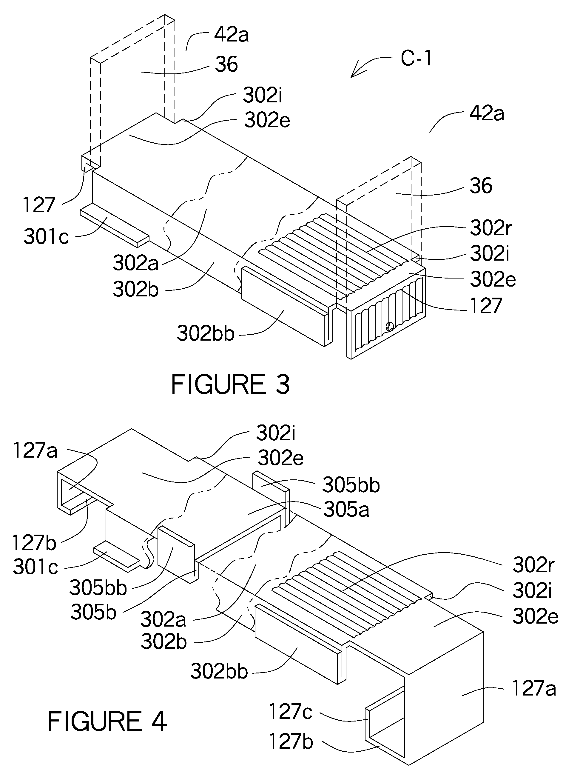
[0018] FIG. 3 shows a downward oriented U shaped spacer brace with alternative spacer brace shapes including ridges in the dorsal and hook finger shapes, lips at the ends of the flanges and double thick flange.
[0019] FIG. 4 shows a downward oriented U shaped spacer brace with U shaped finger ends.
[0020] FIG. 5 shows U-shaped spacer brace in a horizontal position with its downward oriented flanges having the jagged edges and the hook fingers having abrasive protrusions on its inside surface.
[0021] FIG. 6 shows a U-shaped spacer brace in a horizontal position with its flanges oriented upward with bent flaps engaging one surface of the support member and the downward oriented hook finger engaging the opposite side of the support member.
[0022] FIGS. 7A, 7B & 7C shows the steps required in order to install six spacer braces intersecting a one hole in the support member.
[0023] FIG. 8 shows an enlargement of the six spacer braces intersecting in one hole however the horizontal spacer brace is shown as a continuous horizontal bracing channel for clarification and a reverse lip brace with notches in the lips are secured to the sides of the hole and the reverse lip brace has angles notches for the top sides of the diagonal spacer braces could be installed in the angled notches.
[0024] FIG. 9 shows how the spacer braces are oriented horizontally but are installed diagonally between support members where the hook fingers extend through the holes of adjacent support members.
[0025] FIG. 10 shows the spacer braces installed diagonally with the hook tongues overlapping each other at the web of the support member.
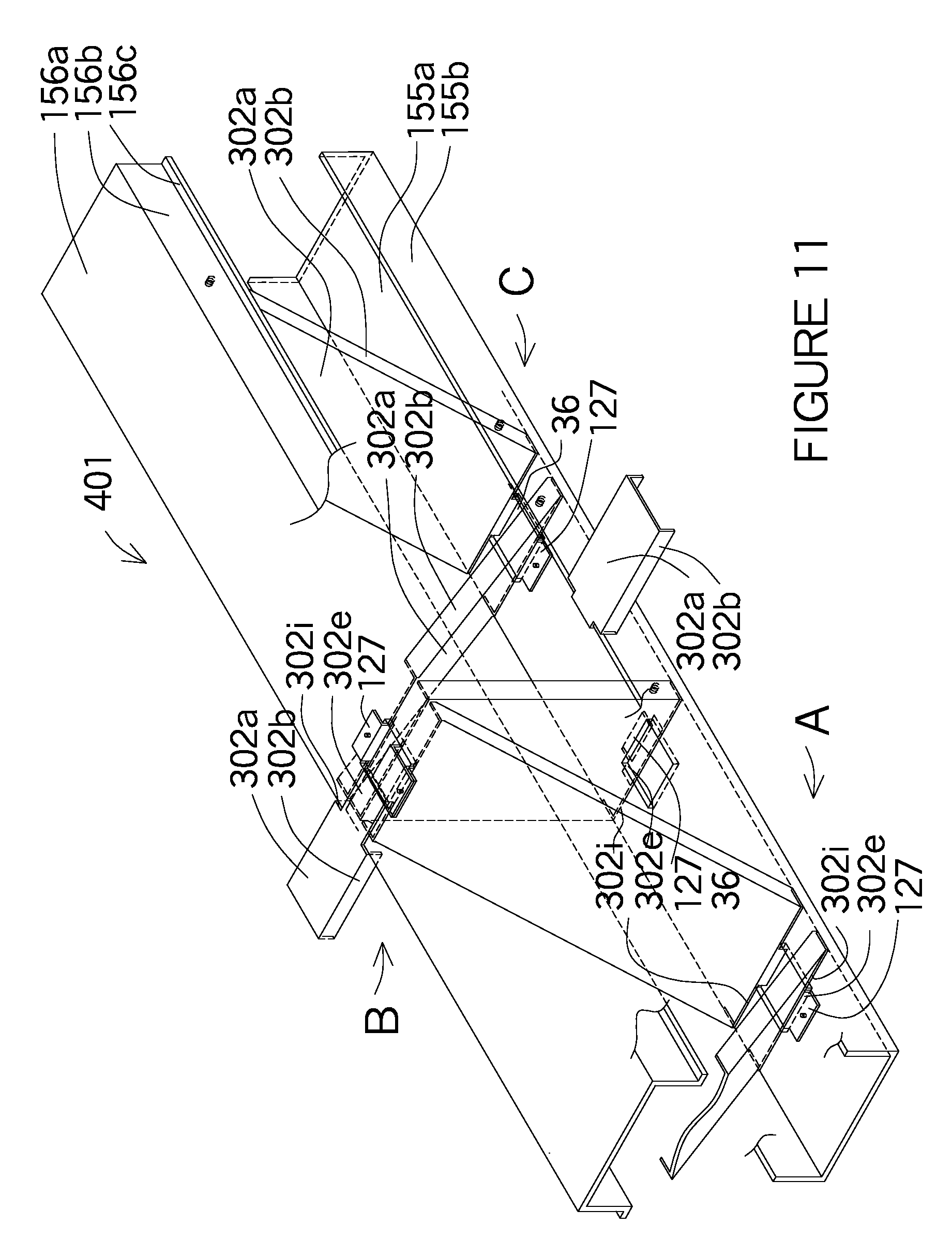
[0026] FIG. 11 shows the horizontal, diagonal spacer braces installed together to form a truss joist.
[0027] FIG. 12 shows a truss joist using metal framing where the top cord has a horizontal web and the bottom chord having a vertical web connected by spacer braces.
[0028] FIG. 13 shows the same configuration as FIG. 12 except two spacer braces are used in lieu of only one.
[0029] FIG. 14 shows eleven different space brace configurations each oriented differently on the vertical support member with some spacer braces passing through triangular or square shaped holes and others passing over the flanges of the support member.
[0030] FIG. 15-17 show three different spacer brace configurations passing through the triangular shaped hole shown in FIG. 14.
[0031] FIG. 18 shows three wood horizontal joists or the bottom chord of the truss joist where the spacer braces connect the horizontally oriented support members together either horizontally at the top or bottom edges or as a diagonal between support members.
[0032] FIG. 19 shows three horizontally oriented metal support members being connected at the top, bottom or through the holes of the support members as well as being connected diagonally.
[0033] FIG. 20 shows a cross section or a wood truss joist having spacer braces connecting the top and bottom chords of the truss joist and the spacer braces used as horizontal or diagonal lateral bracing between truss joists.
[0034] FIG. 21 shows a similar cross section of a truss joist as FIG. 20 however the horizontal support members are vertical oriented metal members with the spacer braces being the vertical or diagonal chords or the lateral bracing between the truss joists.
[0035] FIG. 22 shows the U-shaped spacer brace in a vertical position with jagged edges at the ends of the flanges and punched teeth extending from the web into the support member.
[0036] FIG. 23 shows both a wood and C channel as the support member with one diagonal spacer brace being attached by fasteners and other spacer brace with its jagged edges at the flanges and punched teeth extending from the web into the support member along with a horizontally oriented spacer brace passing through the hole of the support member.
[0037] FIG. 24 shows a truss joist where the horizontal support members are wood with one spacer brace oriented vertically and the other diagonally both having jagged edges at the flanges and the punched teeth extending into the support members.
[0038] FIG. 25 shows a similar configuration as FIG. 24 except the wood support members are oriented vertically and the diagonal spacer brace is bent so the hook finger is perpendicular to the support member.
[0039] FIG. 26 shows the spacer brace as a beam connecting between support members with cripple type support member defining the window or door opening.
[0040] FIG. 27 shows an enlargement of the punched hole teeth at the extension and the jagged edges at the flange ends.
[0041] FIG. 28 shows the beam with jagged edges at the end of the finger and the double flange.
[0042] FIG. 29 shows an enlargement of FIG. 28 at the connection of the framing member.
[0043] FIG. 30 shows the end of the finger as a U-shape being connected to the lip of the support member when being used as a beam.
[0044] FIG. 31 shows an enlargement of the connection at the support member.
[0045] FIG. 32 shows the spacer brace as a beam for C channels using U-shape or L-shapes at the ends of the fingers supporting the beam.
[0046] FIG. 33 shows an enlargement of the connection in FIG. 32.
[0047] FIG. 34 shows an isometric view of two vertically oriented spacer braces installed on opposite sides of the same hole in a vertical oriented support member.
[0048] FIG. 35 shows an enlarged view of each end of the spacer brace when intersecting holes as shown in FIG. 34.
[0049] FIG. 36 shows an isometric view of a spacer brace at the intersection of an outside corner using wood support members.
[0050] FIG. 37 shows an isometric view of spacer braces connecting wood support members at an outside corner.
[0051] FIG. 38 shows an isometric view of a spacer brace at the intersection of an outside corner using metal support members.
[0052] FIG. 39 shows an isometric view of spacer braces connection metal support members at an outside corner where the end of the spacer braces have a tongue side and a receiver side for connecting spacer braces in tandem.
[0053] FIG. 40 shows an isometric view of an outside corner having a vertically oriented spacer brace located on the outer edges connecting the wood support members from two intersecting wall panel sections.
[0054] FIG. 41 shows the same isometric view as FIG. 36, however a diagonal spacer brace is installed on the outside side edges of the wood support members where the spacer brace has its dorsal oriented vertically and the ventral flanges are full depth.
[0055] FIG. 42 shows the same isometric view as FIG. 36 except the spacer brace has an L-shaped hook finger connecting the lip of an adjacent wall panel and a C-shaped hook finger attaching the lip of different oriented metal framing members of another wall panel.
[0056] FIG. 43 shows the same isometric view as FIG. 38, however a diagonal spacer brace is installed on the outside side edges of the metal support member where the spacer brace has its dorsal oriented vertically and the ventral flanges are full depth.
[0057] FIG. 44 shows an isometric view of a spacer brace that is shown in FIG. 35, however the spacer brace has a U-shape channel where the dorsal fits into the ventral side of a C-shape channel that is slightly larger for the smaller U-shape channel to fit into. One end of the spacer brace has a finger and the oppose end has a U-shape hook that fits around an adjacent wall panel.
[0058] FIG. 45 shows an isometric view of the telescoping spacer brace fitting together as shown in FIG. 40.
[0059] FIG. 46 shows an isometric view of a partial wall using wood support members with a spacer brace connecting three wood support members with notched flanges and the ends having fingers that wrapped around the side of the wood support members. Another spacer brace below is the same as above except the web of the spacer brace is oriented horizontally and the hook fingers are connected between the wood support members.
[0060] FIG. 47-49 shows an isometric, section and plan view of a spacer brace and the hold-down connecting adjacent metal support members at the floor.
[0061] FIG. 50-52 shows an isometric, section and plan view of a spacer brace and the hold-down connecting adjacent wood support members at the floor.
[0062] FIG. 53 shows an isometric view of a one piece hold-down spacer brace-bracket between metal framing with the hook finger connecting the opposite side of the support member.
[0063] FIG. 54 shows an isometric view of a one piece hold-down spacer brace-bracket between wood framing with the hook finger connecting the opposite side of the support member.
[0064] FIG. 55 shows an isometric view of a one piece hold-down spacer brace-bracket between metal framing without the hook finger.
[0065] FIG. 56 shows an isometric view of a one piece hold-down spacer brace-bracket between wood framing without the hook finger.
[0066] FIG. 57 shows a fold out profile of a one piece hold-down spacer brace-bracket shown in FIGS. 53 & 54.
[0067] FIG. 58 shows a fold out profile of a one piece hold-down spacer brace-bracket shown in FIGS. 55 & 56.
DESCRIPTION OF THE PREFERRED EMBODIMENTS
[0068] FIG. 1 shows an elevation of a metal or wood framed wall showing various clouds or cut away areas of the spacer brace configurations explained in the various figures noted in the drawings. C-1 could be a horizontally oriented spacer brace spanning between the holes in metal support member or spacer braces mounted on the flanges of wood or metal framing or hold down spacer braces mounted on the floor. C-2 could be a continuous spacer brace spanning between intermediate support members at the hole or on the flanges, or individual spacer braces installed in a continuous line in the holes or on the flanges between support members or individual spacer braces installed on both side edges of the hole. C-3 could be spacer braces installed over the flanges or through the holes of wood or metal support members to form a continuous diagonally oriented spacer braces. C-4, C-5 & C-6 show spacer braces mounted on the top and bottom edge of the hole and through the middle of the hole in a metal support member or could be spacer braces mounted between support members or over their respective flanges. C-7 is similar to C-4; C-5 & C-6 except here the configuration is forming a beam above a window. In C-8 the horizontal support members could be wood or metal with the spacer braces used as vertical and diagonal cords to form floor joists and shown with lateral bracing at the top, bottom and connects at the lips of the support members. In C-9 wood floor joists are shown as well as truss joists using wood or metal support members having spacer braces as vertical and diagonal chords of truss joists as well as horizontal and diagonal lateral bracing at the top, bottom or through the holes of the support members. The spacer braces have same characteristics but are used in different applications.
[0069] FIG. 2 shows a single spacer brace as shown as C-1 or C-9 in FIG. 1 of an isometric of a downward oriented U shaped spacer brace 302 with the web 302a having the dorsal side at the top side with two parallel flanges 302b extending ventrally downward from the web 302a and shown installed in a hole 36 (shown in ghost) at the web 42a between support channels shown as a C channels 42. In FIG. 1 the cloud formation C-1 has the support member shown vertically and in C-9 the support member is horizontal, but in both cases the U shaped spacer brace 302 is shown passing through a hole 36. The U shaped spacer brace can be equal in width of the hole 36 or wider than the hole 36. The web 302a has an indentation 302i, with an extension 302e so the hook finger 127 fits against the bottom edge of the hole 36 and against the web 42a of the support member. The web 302a and the parallel flanges 302b fit against the opposite edge of the web 42a forming an indentation 302i securing the U shaped spacer brace 302 to the hole 36. The hook finger 127 can be longer so a fastener can be used to secure the hook finger 127 to the web 42a or to another hook finger 127 should one hook finger 127 be installed over another hook finger 127 as shown in FIGS. 7 & 10 when installed at an angle. The single spacer brace can also be used as a base plate at the floor as shown as C-1 in FIG. 1. The U shaped spacer brace 302 can be used as a spacer to evenly space the support members within the wall framing or as a full width base plate typically used in building construction.
[0070] FIG. 3 and FIG. 4 show an isometric drawing of a spacer brace having different configurations. One variation shows a downward oriented U shaped spacer brace 302 having an elongated body with a web 302a having two flanges 302b extending downward from the ventral side of the web 302a. The U-shaped spacer brace 302 is shown where the dorsal is oriented horizontally and two flanges 302b extend downward from the ventral side. Another variation shows a reverse lip spacer brace 301 having a U shape with a lip 301c extending from the bottom edge of the flange 30bb in an outward direction away from the web 301a and better shown as a reverse lip brace 301 in FIG. 14. Another variation of the U shaped spacer brace 302 has the flange 302b shown as a double flange 302bb where the flange 302b is bent twice to increase the strength. Another variation shows an I shape spacer brace 305 where the flanges 305b and 305bb are slightly different than the reverse lip brace 301 as the flange 305b extends downward from the web 305a then bents upward to form flange 305bb, but extends above the web 305a forming an I shape at the both flanges. By forming grooves, indentations or ribs 302r in the direction of the elongated spacer brace the metal surface is broken and the ribs 302r will increase the strength of the elongated spacer brace. The thickness of the metal to form the spacer brace can increase in thickness to increase the strength of the spacer brace. The left side shows and an indentation 302i extend from the flanges 302b and into the web 302a where the web 302a has an extension 302e with a hook finger 127 extending ventrally downward forming an L-shaped hook where the first leg is 127a and the second leg 127b for an L-shape. The right side shows a U-shape at the end of the hook finger 127 where the first leg is 127a, then bent again shown as 127b, then bent upwards shown as 127c. The L-shape can be used where the hook finger 127 extends into the hole 36 in the web 42a of a support member and the U-shape can be used where the hook finger 127 extends around the lip 42c of the support member.
[0071] FIG. 5 is similar to FIG. 22 except the wood framing members 68 are oriented horizontally instead of vertically as shown in FIG. 1 in C-8 at the rafters or truss joists. The U-shaped spacer brace 302 has the dorsal horizontally oriented and the flanges 302b extend ventrally downward with the jagged edges 74 penetrating the wood framing members 68. The dorsal side of the web 302a can have holes for nails to penetrate the wood framing members 68 or punched hole teeth 70. The ventral side of the hook finger 127 has dimples 125 as an abrasive means for a better connection since wood framing members 68 usually have an uneven surface. Punched hole teeth 70 are shown on the dorsal side of the extension 302e in the U-shaped spacer brace 302 so the teeth 70t for the punched hole 70h can penetrate the wood framing member 68.
[0072] FIG. 6 is similar to FIG. 2, however the U-shaped spacer brace 302 is facing upward and the web 302a has the dorsal side on the bottom side. When the width of the U-shaped spacer brace 302 is equal or narrower than the width as the hole 36, the web 302a is narrower than the bottom edge of the hole 36 and the extension 302e passes through the hole 36 then bent over the bottom edge of the hole to form an hook finger 127. There is no indentation 302i since the width of the web 302a is smaller than the width of the hole 36. The flanges 302b extend upward from the web 302a of the U-shaped spacer brace and the ends of the flanges 302b have a flap 76 that is bent so the sides of the flaps 76 brace against the web 42a of the support members.
[0073] FIGS. 7A, 7B & 7C is similar to C-5 & C-6 in FIG. 1 as the spacer braces are shown diagonally installed in the metal framed wall where six intersecting U shaped spacer braces 302 intersect at the same hole 36 and all the U shaped spacer braces 302 are wider than the hole 36. In order to show the U shaped spacer braces 302 being continuous FIGS. 7A, 7B & 7C show an enlargement of three different holes 36 in the support members as additional U shaped spacer braces 302 intersect at the holes 36 in the support member. The diagonally oriented spacer braces 302 are shown having the dorsal side of the web 302a with its top side facing upward with the two parallel flanges 302b extending ventrally downward along with a horizontally oriented spacer brace 302 having the web 302a on the downside with the two parallel flanges 302b extending ventrally upward. FIG. 7A shows two diagonally oriented spacer braces where the right U shaped spacer brace 302 has the extension 302e and hook finger 127 passes through the hole 36 with the hook finger 127 bent parallel to the web 42a of the support member and the left U shaped spacer brace 302 has the extension 302e and hook finger 127 pass over the right U shaped spacer brace 302 with the right hook finger 127 fastened to the top side of the right U shaped spacer brace 302. FIG. 7B shows the two upward facing horizontally oriented U shaped spacer braces 302 having the dorsal side on both ends of the bottom side of the web 302a of each U shaped spacer brace 302 having notches 126 at the end or notch-web fingers 127n. The notch-web finger 127n passes through the hole 36 and the end of the notches 126 has tabs 126t at the end that give support to the notches 126 when extending past the hole 36. The notch 126 is formed by installing the notch 126 at the side edges of the web 302a leaving the notch 126 having the web 302a on one side and the opposite side having a tab 126t be the remaining end of the notch-web finger 127n. The notch-web finger 127n of the adjacent horizontally oriented U shaped spacer brace 302 is placed over the notch-web finger 127n of the first horizontally oriented spacer brace 302 with its notch 126 and tab 126t engaging the hole 36. Since the horizontally oriented U shaped spacer braces 302 are wider than the hole 36 the edges of the web 42a and two parallel flanges 302b abut the web 42a for the support member as well as the tab 126t at the end of the notches 126. FIG. 7C and enlarged as FIG. 8 shows a upward orient bracing member shown as a horizontal bracing channel 155 passing through the hole 36 with the dorsal side of the web 155a as its bottom side with the two parallel flanges 155b extending ventrally upward. A one piece multi-plane brace 301 having the dorsal side of the web 301a and the two parallel flanges 301b placed within the horizontal bracing channel 155 so the dorsal sides of the web 301a and flanges 301b abut the top side or ventral side of the web 155a and flanges 155b leaving the lips 302c extending over the top edge of the flanges 155b so the web 24a can be inserted into the notches 126 in the lip 301c securing the one piece multi-plane brace 301 into place at the hole 36. The upward facing one piece multi-plane brace 301 also has angular oriented notches 126 installed in the lips 301c and the upper side of the two parallel flanges 301b forming continuous notches 126. Diagonally oriented U shaped spacer braces 302 have their web 302a with its dorsal side facing upward on its top side into the diagonally oriented notches 126 and where the opposite end is shown being installed in FIG. 7A. FIG. 8 shows an enlargement of FIG. 7C. Whether the spacer braces or U shaped or reverse lip shapes, upward facing or downward facing the spacer braces are interchangeable as well as most of the interlocking connections at the hole 36.
[0074] FIG. 8 is similar an enlargement of FIG. 7C. The support member is shown as a U channel 155 and the web 155a has the hole 36. All the horizontal oriented and diagonal spacer braces 302 are shown with the width of the webs 302a fit between the parallel flanges 155b and the diagonally oriented spacer braces 302 have indentations 302i, extensions 302e and hook shapes upward or downward oriented connect to the top or bottom edge of the hole 36 or connect to the web 302a of the adjacent diagonal spacer brace 302. The horizontal oriented spacer braces 302 have the same notch 126 and tab 126t configuration as described in FIG. 7C.
[0075] FIG. 9 shows two diagonal spacer braces 302 spanning between the holes 36 of two support members shown as a C channel 42. The U shaped spacer brace 302 face downward with the dorsal side being on the top side with the two flanges 302b extending ventrally downward. The end of each U shaped spacer brace 302 has the hook fingers extending through the hole 36 with the extension 302e abutting the top or bottom edge of the hole 36 with an indentation 302i occurring at the hole 36 where the web 302a is wider than the hole 36. The isometric drawing shows two support members as C channels 42 with holes 36 in the web 42a with downward facing U shaped spacer braces having the dorsal on the top side shown as web 302a and two flanges 302b extending outward and spanning between the holes 36 at a diagonal. The hole 36 in Drawing A shows a U shaped spacer brace 302 spanning from the bottom edge of hole 36 to the upper edge of hole 36 in Drawing B. Another U shaped spacer brace 302 spans from the bottom edge of hole 36 in Drawing B to the upper edge of hole 36 in Drawing C. Each of the U shaped spacer braces 302 are wider than the width of the hole 36 and the extension 302e with a hook finger 127 pass through the hole 36, that is bent either upward or downward and are fastened to the web 42a of the support member. The configuration of the hole 36 allows for a continuous horizontal bracing member or spacer brace to pass through the hole 36 adding additional horizontal structural bracing between support members.
[0076] FIG. 10 also shows the diagonally oriented U shaped spacer braces 302 however two additional diagonally oriented U-shaped spacer braces 302 have been add plus the hole 36 could have additional horizontal spacer braces added. The diagonally oriented U-shaped spacer braces 302 have the dorsal on the top side have a web302a and two flanges 302b extending downward. The upper left U-shaped spacer brace 302 shows the an indentation 302i at the flanges 302b and at the web 302a leaving and extension 302e extend through the hole 36 and bent at the hook finger 127 upward and the right U-shaped spacer brace 302 also has the indentation 302i and extension 302e so the hook finger 127 can be bent downward and fastened together. The lower left U-shaped spacer brace 302 shows the an indentation 302i at the flanges 302b and at the web 302a leaving and extension 302e extend through the hole 36 and bent at the L-shaped hook finger 127 downward and the right U-shaped spacer brace 302 also has the indentation 302i and extension 302e so the L-shape hook finger 127 can be bent upward and fastened together. Since the L-shape hook finger 127 aligns with the flange 302b an indentation 302i occurs at the web 302a. Since both U shaped spacer braces 302 intersect at the same top or bottom edges of the hole 36 the extensions 302e and the ends of the hook finger 127 overlap each other and will become fastened together after being installed.
[0077] FIG. 11 is an isometric view of a horizontally oriented truss joist 401 which can be used as a window or door header shown as vertical wall framing in FIG. 10 and shown in the elevation of FIG. 1. The horizontally oriented truss joist 401 is shown having diagonally oriented U shaped spacer braces 302 span between holes 36 in the horizontally oriented support members shown as a C shaped channel 42 having a horizontally oriented web 42a with two vertically oriented parallel sides 42b with lips 42c extending inwardly from the parallel sides for additional strength if required. The width of the U shaped spacer braces 302 are wider than the width of the hole 36 and only the extension 302e and the hook shape extend through the hole 36 where the hook finger 127 braces the web 42a on one side and the ends of the top side 302a or bottom side 302d of the U shaped spacer brace 302 plus the ends of the two parallel sides secures the U shaped spacer brace 302 to the horizontally oriented support member. A vertically oriented U shaped spacer brace 302 (shown in ghost) are required to be wider than the diagonally oriented U shaped spacer braces 302 in order to fit around the two parallel sides 302b with the extensions 302e and the hook finger 127 fitting through the holes 36 and engaging the hole 36 at the hook finger 127 and the edges of the top sides 302a or bottom side 302d and the two parallel sides fitting against the web 42a. The vertical spacer brace is sometimes required to distribute the structural load forces within the truss joist.
[0078] FIG. 12 is similar to FIG. 24 as they are both truss joist 401; however the FIG. 12 uses metal framing member as the support members. The top chord (shown in ghost) shows a C channel 42 with the dorsal side having a web 42a oriented horizontally with two sides extending vertically with lips 42c extend horizontally inward to each other and are parallel to the web 42a. The lower chord (shown in ghost) of the truss joist 401 shows a C channel with a vertical dorsal having a web 42a with two sides extending outwardly connected with lip extending inwardly toward each other. The U-shaped spacer braces 302 connect the top and bottom chords where the dorsal sides are vertical and have a web 302a with two extending sides 302b that abut the ventral side of the lip 42c of the upper chord and the top side of flange 42b of the bottom chord. The web 302a of the U-shaped spacer brace 302 has an indentation 302i and an extension 302e that extends over the upper chord flange 42b and the web 42a of the lower chord and both the hook finger 127 wraps around the chords of the truss joist 401 at the top side 42a of the horizontally oriented chord and the bottom side flange 42b of the bottom chord. The diagonally oriented spacer braces continually are placed between the top and bottom chords at repeating intervals until the truss joist 401 has reached its designated length. The left diagonally oriented U-shaped spacer brace 302 shows the top chord of the truss joist 401 having the extension 302e and the hook finger 127 extended parallel to the direction of the spacer braces rather than perpendicular as previously shown.
[0079] FIG. 13 is a double of FIG. 12. The lower chord (shown in ghost) has another horizontal C channel 42 adjacent to the first C channel where the lips 42c abut each other. Since the top chord (shown in ghost) is orientated horizontally that is the dorsal is horizontal rather than vertical, the second U-shaped spacer braces 302 can be installed as described in FIG. 12.
[0080] FIG. 14 is a cross section through a metal framed wall showing numerous sizes and shapes of spacer braces being attached to a C channel 42. The spacer braces are oriented vertically, horizontally or at an angle and can be mounted within the hole or on the exterior surface or flange 42b usually secured to the web 42a by the hook fingers 127. The holes 36 within the web 42a are usually rectangular in shape, however a triangular shape hole 36t is also shown showing three various spacer braces in FIGS. 15-17. The U-shaped spacer braces 302 near the bottom show one U-shaped spacer brace 302 where the dorsal is oriented on the top side and the sides are extending downward while the other U-shaped spacer brace 302 the dorsal is oriented on the bottom side and the sides 302b are extending upward. The reverse lip spacer brace 301 on the right side of the support member is installed so the extension 301e (not shown) at the web 301a can extend over the flange 42b so the hook finger 127 can be connected to the web 42a of the support member. On the left side the reverse lip spacer brace 301 is installed so the lips 301c are supported at the flange 42b. The reverse lip spacer brace 301 also on the left by further down the wall, shows the side 301b at an angle like a hat channel shape. Just below is a U-shape spacer brace 302 that shows a double flange 302bb and the edge of the double flange 302bb is against the flange 42b of the support member. In addition, the U-shape spacer brace 302 shows a light weight line below the U-shape spacer brace 302 which references that the U-shape space brace 302 is shows the spacer brace has been installed diagonally over the support members. The hook finger 127 shown on the U-shape spacer brace 302 with the double flange 302bb is a hook finger 127 having an L-shape where the hook portion extends over the edge of the hole 36 as shown in FIGS. 32 & 33. The lower triangular hole 36t shows three U shaped spacer braces 302 one shown at an angle and two shown on the right vertical edge where one U shaped spacer brace 302 is spanning away and another is spanning forward. A C-shaped spacer brace 303 has its dorsal vertical where the lips 303c are installed on the flange 42b of the C-channel 42 with a hook finger 127 having three sides wrapped around the lip 42c and the flange 42b. The extension 303e does not need to be connected to the flange 42b of the C channel 42 since the hook finger 127 connects this end of the C-shaped spacer brace 303. The end of the hook finger 127 can have an additional two or three side add at the end of the hook finger 127 so the C-shaped spacer brace 303 must first connect the C-shape to the lip 42c then rotate the C shaped spacer brace 303 almost 180 degrees until the extension 303e is at the flange 42b of the adjacent support member. Also see FIGS. 30-36 where the hook finger 127 forms an L or C shape. The metal framed wall has a U-shape spacer brace 302 with its dorsal side anchored to the floor 401 with an anchor bolt assembly 354 that is connected through a hole 36 in the web 302a. The U-shaped space brace 302 shows the flanges 302b abutting the web 42a of the support member shown as a C channel 42. The opposing side of web 42a has the ventral side of the hook finger 127 mounted with fasteners to the web 42a. If the support member were wood framing members 68 the web 302a and flanges 302b would be similar to other previously described connections for wood construction. The floor mounted U-shaped spacer brace 302 also referred to as a hold-down spacer brace 309 can also be mounted at the top of the wall making the same connections to the support members and the horizontal plate at the top of the wall as shown in FIGS. 18-21. Some building codes require that the support members should have a gap between the top plate and the end of the top edge of the web 42a & flange 42b of the support member in order for floor joists above to deflect. When this occurs the fasteners 122 are installed in the slot holes 36s and the spacer brace 302 is allowed to move in an up and down motion as the web 302a is secured to the support member above.
[0081] FIGS. 15-17 show three different spacer braces being connected at a triangular shape hole 36t shown at the web 42a of a C channel 42. The reverse lip spacer brace 201 shows the dorsal side at an angle so the web 301a and sides 301b can fit into the triangular shape hole 36r, however the lips 301c act as a flap 76 as shown in FIG. 16 where the ends of the lips 301c abut the web 42a on one side and the web 301a has an indentation 301i and then an extension 301e so the hook finger 127 can extend over to the opposite side of the web 42a and the ventral side of the hook tongue 128 can abut the web 42a and fastened by a screw 122 into the web 42a. FIG. 16 shows the web 302a and the side 302b extending through the triangular shape hole 36t and flaps 76 that extend away the angular oriented sides 302b. The flaps 76 are rectilinear in shape and are perpendicular to the sides 302b. FIG. 17 shows an elevation of the U-shaped spacer brace 302 where the hook finger 127 is fastened with screws 122 on the viewers side of the web 42a, the extension 302e is the thickness of web 42a of the support member and the indentation 302i, web 302a and the side 302b is on the opposite side of the web 42a. Some spacer braces are attached to the web 42a or by the hook finger 127. None of the holes 36 show a lip or also described as a rim (not shown) at the edge of a hole 36 in the web 302a. Some metal framing manufacturers leave a rim at the edge of a hole 36. The rims, holes 36, or lips 302c of C-shaped channels 42 can have L-shaped or U-shaped fingers on the various spacer braces as shown in FIG. 33.
[0082] FIG. 18 shows three wood joists as wood framing members 68 (shown with light weight lines) where the top surface of the wood framing members 68 show a U-shaped spacer brace 302 (in section) being connected together. The dorsal side is on the top side of the U-shaped spacer brace 302 and the sides 302b extend downwardly from the web 302a. The U-shaped spacer braces 302 are staggered next to each other and therefore look like the U-shaped spacer braces 302 are over lapping. The end of each side has engagement means of a hook finger 127 that engage on side of the wood framing member and the edges of the sides 302b abut the wood framing member on the opposing side. The edges of the sides 302b are shown with jagged edges 74. At the bottom of the left wood framing member 68 shows a U-shaped spacer brace 302 at a diagonal where the dorsal is on the top side shown as the web 302a with the flanges extending downward. The web 302a is shown having a hook finger 127 where side 127a is bent down, side 127b is horizontal and side 127c is vertical encasing the bottom side of the wood framing member 68 on three sides. In addition, the flanges 302 from the U-shaped spacer brace 302 have jagged edges that extend into the wood framing member 68. On the right side shows the same U-shaped spacer brace 302 that is on the top side of the wood framing members 68, however the web 302a with its extension 302e on the ventral side at the bottom edge of the wood framing members 68 and the flanges 302b and hook finger 127 are extending upward.
[0083] FIG. 19 shows three horizontal support members as C channels 42 having a vertical dorsal as a web 42a with two horizontally extending flanges 42b and with lips 42c. The left support members shows a diagonally oriented dorsal of U-shaped spacer brace 302 having the top side as a web 302a with extending downward flanges 302b. The extension 302e that extends from the web 302a is bent at angle parallel to the flange 42b and bent at the hook finger 127 over the lip 42c. An diagonally oriented U-shaped spacer brace 302 is shown connecting the left C channel 42 to the middle C channel 42 at the top edge of the hole 36 in the web 42a of the C channel 42. The diagonally oriented U-shaped spacer brace 302 has the dorsal on the top side shown as the web 302a with the extension 302e passing through the upper edge of the hole 36 for the hook finger 127 to be bent upward and secured to the web 42a of the support member. The left C channel 42 shows a horizontally oriented U-shaped spacer brace 302 having the dorsal on the bottom side where the web 42a is horizontal and the flanges 42b are extending upward. The web 302a has the extension 302e passing through the bottom edge of the hole 36 and the hook finger 127 extends downward over the web 42a. The middle and the right horizontal support members have a hole 36 at the bottom edges of the hole 36. A U shaped spacer brace 302 is shown spanning between the adjacent horizontally oriented support members where the web 302a has the dorsal side facing upward with the flanges 302b extending ventrally downward where the right side has the ends of the flanges 302b abut the web 42a of the support member with the extension 302e extending into and over the hole 36. The hole 36 is large enough so two U shaped spacer braces 302 can pass through the same hole, however the U shaped spacer braces are aligned adjacent to one another and therefore alternate between support members forming a checkerboard pattern. The same is true should the U shaped spacer brace 302 want to be installed diagonally that is one end attached at the bottom edge of the hole 36 and the opposite end attached at the top of the support member. This type of arrangement again requires a larger size hole 36 so two U shaped spacer braces 302 could be installed on the bottom edge of the hole 36. At the bottom of the C channel 42 a U shaped spacer brace 302 where the extension 302e passed over the flange 42b and the first leg 127a of the hook finger 127 is bent over the lip 42c with the second leg 127b extending over the edge of the lip 42c with the flanges 302b abutting the web 42a of one support member and the lip 42c of an adjacent C channel 42 with the opposite end having the extension 302e extend under the flange 42b and bent upward forming the hook finger 127 abutting the web 42a of the second C channel 42.
[0084] FIG. 20 shows a truss joist where the support members are shown as wood framing members 68. The wood bracing members 68 can be parallel or angular like a scissor truss. The left truss joist shows the U-shaped spacer brace 302 in section where the web 302a, extension 302e and hook finger 127 are shown darker as well as the wood framing member 68. The U-shaped spacer braces 302 can be angular parallel to the wood framing members 68. The right truss joist shows the U-shaped spacer braces 302 in elevation with the wood framing members 68 shown in section. Diagonal lateral bracing is shown between the two truss joists as the U-shaped spacer brace 302 where the extension 302e is bent to form to the angle of the wood framing members 68 and bent again at the hook finger 127. The U-shaped spacer braces 302 shown in FIG. 20 can be used to connect the truss joists.
[0085] FIG. 21 shows two truss joists where the support members are C channels 42 where the web 42a is oriented vertically with the flanges 42b extending horizontally and the lips 42c are vertical extending inward to each other. The support members are located on the top and bottom chord of each truss joist with U-shaped spacer braces 302 are installed vertically and diagonally between support members as shown in FIGS. 10, 12, 14 & 15 where the flanges 302b abut the flanges 42b and the webs 302a have an extension 302e that extends over the web 42a with hook fingers 127 extending over the top and bottom flanges 42b of the support member. Three U-shaped spacer braces 302 are shown horizontally between truss joists and are used as lateral bracing between the truss joists. At the top and bottom chords a U-shaped spacer brace 302 is shown where the dorsal is on the top side and the flanges 302b extend downward with their vertical edges abutting the lip 42c and web 42a. The webs 302a have an extension 302e extend over the top flanges 42a some secured directly into the flanges 42b while others have the hook finger 127 extend over the webs 42a and or lips 42c. The U-shaped spacer braces 302 can be installed diagonally between the top and bottom support members or diagonally along the top or bottom chords along the flanges 42b when the truss joists are installed in an array. A third U-shaped spacer brace 302 that is oriented downward is installed in the hole 36 at the web 42a of the C channel 42 used as the support member. The edges of the flanges 302b abut the webs 42b with an extension 302e passing through the hole 36 and the ventral side of the hook fingers 127 abut the web 42a on the opposite side of the web 42a from the flanges 302b. At the bottom of the truss joists a U-shaped spacer brace 302 also referred to in the building trades as the top plate which connects the vertical support members similar to the U-shaped spacer brace 302 shown at the floor in FIG. 16 to the top end of the support members. Since the U-shaped spacer brace 302 is upside down the dorsal side is abutting the truss joists and the hook fingers 127 are resting on the dorsal side. The right side shows a hook finger 127 with a U-shape having the first leg 127a extend from the extension 302e ventrally upward against the lip 42c extending over the top edge is leg 127b then leg 302c extends over the back side of the lip 42c of the lower horizontal chord of the truss joist while the left hook finger 127 has the first leg 127a extend upward from the web 302a against the lip 42c then extend over the top edge of the lip 42c forming an L-shape that is also wrapped around the lip 302c of the adjacent lower horizontal chord of the truss joist. The fingers of the top plate can also just be hook finger 127 connecting the webs 42a of the bottom horizontal chord. Another option is have one U-shape spacer brace 302 attach to the support members of the wall framing members and another U-shaped spacer brace 302 attach to the truss joist where the webs 302a or each U-shaped spacer brace has their dorsal side attached back-to-back where one set of flanges 302b extend downward and another set of flanges 302b extend upward. A U-shaped spacer brace 302 is shown at the top of the truss joists.
[0086] FIG. 22 has a U-shaped spacer brace 302 that is installed with the web 302a in a vertical orientation and installed with the ventral side installed over the vertically oriented wood framing members 68. In FIG. 22 the U-shaped spacer brace 302 is shown as an independent spacer brace connected between two support members. The web 302 has two flanges 302b extending outwardly with jagged edges 74 at the ends of the flanges 302b that penetrate into the wood framing members 68 and the webs 302a have indentations 302i and an extensions 302e that extends over the surface of the extension 302e on both wood framing members 68 and the hook finger 127 of the spacer brace 302 is bent parallel to the angle of the wood framing member which is typically 90 degrees. In this figure the web 302a is oriented vertically so the ventral side of the U-shaped spacer brace 302 is against the vertically oriented wood framing members 68 and the ventral side of the hook finger 127 abuts the side edges of the wood framing member 68. Fasteners are secured through the extensions 302e and the hook fingers 127 to secure the wood framing members 68. Punched hole teeth 70 are shown on the dorsal side of the extension 302e in the U-shaped spacer brace 302 so the teeth 70t for the punched hole 70h can penetrate the wood framing member 68. In addition, the hook finger 127 on the right side of FIG. 22 can have bumps, abrasions or any other means to create friction between the ventral side of the hook finger 127 at the wood framing member 68.
[0087] FIG. 23 shows an isometric view of a vertical support member either a C channel 42 or a wood framing member 68. Two diagonal framing members both shown as a U-shaped spacer brace 302 where the dorsal side is shown as a vertical orientation with the web 302a extending over the flange 42b of the C channel 42. The upper U-shaped spacer brace 302 is shown for a wood framing member 68, with the extension 302e showing the punch hole teeth 70. The diagonally oriented flanges 302b are shown with a bent flap 76b that extends longer and reinforces the flanges 302b and the extension 302e extends onto one side of the wood framing member 68 and the hook finger 127 extending over the opposite side of the wood framing member 68. The downward diagonally oriented U-shaped spacer brace 302 is shown with fasteners extending into the flange 302b and web 302a of the C channel 42. Between the two diagonal U-shaped spacer braces 302 is a horizontally oriented U-shaped spacer brace 302 shown in FIG. 22.
[0088] FIG. 24-25 are similar except in FIG. 24 the wood framing members 68 are shown as horizontal support members to form truss joists 401 that are shown in C-8 in FIG. 1. Truss joists 401 are typically joists that have a horizontal top and bottom chord (shown in ghost) shown as wood framing members 68 and diagonal chords connect the top and bottom chords shown in FIGS. 24 & 20 as U-shaped spacer braces 302. In FIG. 25 the wood framing members 68 (shown in ghost) are vertical support members for a wood framed wall and the U-shaped spacer braces 302 are used as lateral and diagonal bracing between the support members. The wood support members 68 in FIG. 24 are shown parallel to each other for a floor joist, however if the top member was at an angle a triangular truss could be formed using different length U-shaped spacer brace 302. Since the truss joist 401 are designed to have only one top and bottom chord, the U-shaped spacer braces 302 are independent braces where the dorsal side of the hook finger 127 is vertical and the sides 302b extend outwardly from the web 302a where the top and bottom ragged edges 74 engage to wood framing members and the web 302a is indented 302i and the extension 302e with the punched hole teeth 70 penetrate the wood framing member 68 and the hook finger 127 wraps around the top or bottom side of the wood framing members 68. Screws 122, nails or the punched hole teeth 70 can be used to connect the spacer braces to the wood framing members 68. FIG. 25 shows the same configuration as FIG. 24 except the wood framing members 68 are oriented vertically. The web 302a is oriented vertically and the sides 302b extend ventrally horizontally or diagonally away from the web 302a.
[0089] When the wall construction is oriented vertically the diagonal oriented U-shaped spacer braces 302 are now typically referred to in the building industry and diagonal bracing which is used to reduce horizontal forces such as wind against a building and the horizontal oriented spacer braces are referred to as lateral bracing. These spacer braces or any of the spacer braces described can be U-shaped, C-shaped or C-shaped where the lips extend outward on the dorsal side of a U-shaped spacer brace 302. When the spacer braces are installed diagonally above a door or window the spacer braces are referred to as beams. These beams can have a truss like construction as shown in FIG. 1 can act like a truss as shown in C-7.
[0090] FIG. 26-27 shows the dorsal of a U-shaped spacer brace 302 vertically oriented and spanning between wood framing members where the wood framing member 68 have a tall member and a short member (typically called a cripple within the construction industry) which usually indicates a wood framed opening for beam. The beam is shown having the dorsal vertically oriented with the ventral side of the web 302a and the extension 302e abutting the outer surface 68a with the hook fingers 127 connected to the inner sides of the wood framing members 68. Both ends of the U-shaped spacer bars 302 are connected to the taller member of the wood framing members 68. The extensions 302e on the left side show the punched hole teeth 70 extending from the dorsal side into the wood framing members 68 and the right end shows holes 36 on the extensions 302e and hook finger 127. The jagged edges 74 are shown at the ends of the sides abutting the wood framing members 68.
[0091] FIG. 28-29 are similar to FIGS. 26 & 27, however the sides have a double flange 302bb and the hook finger 127 has an abrasive edge 127e.
[0092] FIG. 30-31 are similar to FIG. 26 except the vertical oriented support members are C channels 42 having a web 42a with extending flanges 42b and lips 42c extending inward. FIG. 30 shows the hook finger 127 on the right end of the U shaped spacer brace 302 having the first leg 127a abut the lip 42c then abut against the edge of the lip 42c then turn again so the third edge is on the backside of the lip 42 forming a U-shaped that wraps around the lip 42c of the C channel 42. To install the U-shape spacer brace 302, one aligns the right end of the U-shape at the hook finger 127 to be parallel to the lip 42c. Once the U-shape of the hook finger 127 is engaged at the lip 42c, the U shaped spacer brace 302 is rotated 90 degrees toward the vertical oriented support members on the opposite end of the metal framed opening for the beam. The extension 302e and hook finger 127 are then connected by fasteners to the opposing metal support members. FIG. 31 shows the enlargement of the U-shape configuration of the hook finger 127.
[0093] FIG. 32-33 are similar to FIGS. 30 & 31 as the right end of the U-shaped spacer brace 302 has the U-shape at the hook finger 127, however the U-shaped spacer brace 302 rotates 90 degrees the left side has the flanges 302b abut the lip 42c with the extension 302e fitting over the flange 302b and the first side 127a of the hook finger 127 extends over the web 42a and the second side 127b extends into the hole 36 in the web 42a of the C channel 42 being the support member for the metal framed beam opening. FIG. 33 shows an enlargement of right end of the hook finger 127 attached to the extension 303e of a C shaped spacer brace 304 and shows flaps 76 turned ventral inward from the flanges 303b that would rest against the web 42a if they were shown in FIG. 32.
[0094] FIG. 34 is an isometric view of two vertically oriented U shaped spacer braces 302 installed horizontally between the holes 36 of adjacent vertical support members so the U shaped spacer braces 302 are installed alternating between the vertical side edges of the holes 36 by allowing each hole 36 to have one U shaped spacer brace 302 spanning between adjacent U shaped spacer braces on the right side on the rear vertical side edge of the hole 36 and between the adjacent U shaped spacer brace on the left side on the front vertical side edge of the hole 36 allowing the U shaped spacer braces 302 to be staggered between the front and rear vertical sides edges of the holes 36. The vertical support member is shown as a C channel 42 having a vertical web 42a with flanges 42b extending ventrally out from the web 42a with lips extending ventrally inward parallel to the web. The U shaped spacer braces 302 have webs 302a where the dorsal sides face inward with the ventral sides facing the vertical side edges of the holes 36 and the ventral sides have flanges 302b extending from the web 302a. One end of the U shaped spacer braces have the ends of the flanges abut the web 42a of the vertical oriented support member. The flanges 302b and the web 302a has an indentation 302i with an extension 302e that extends over the web 42a at the hole 36 so a hook finger 127 can have the first side 127 extend ventrally over the bottom edge of the hole 36. The opposing end of the U shape spacer brace has its flanges 302b abut the web 42a at the hole 36 of the adjacent support member so the flanges 302b engage the web 42a. The end of the flanges 302b abut the web 42a so a hook finger 127 can extend ventrally over the web 42a of the adjacent support member also shown in the enlarged FIG. 35. When the hook finger 127 of the opposing end of the U shaped spacer brace 302 is secured, the U shaped spacer brace 302 is rotated toward the hole 36 so the edges of the flanges 302b engage the web 42a and the hook finger 127 extends over the side edge of the hole 36 securing the U shape spacer brace 302 to the side edge of the hole 36. Another U shaped spacer brace 302 can be installed on the opposite vertical side edge of the hole 36. The top and bottom edges of the hole 36 can also have the U shaped spacer braces 302 have the dorsal sides oriented horizontally through the holes 36 of adjacent support members which was explained above and previously shown in FIGS. 7-11. Fastener 122 can be installed at the hook finger 127, but are optional depending on the structural stress exerted on the holes.
[0095] FIG. 36 shows a U shaped spacer brace 302 installed horizontally between the vertical support members shown as wood support members 68 and oriented in a Y direction and referred to as wood studs 68y. The U shaped spacer brace 302 has a web 302a oriented vertically with the flanges extending ventrally horizontally from the web 302a. At both ends the web 302a has an extension 302e where the ventral side extends over the width side 68w of the wood support member 68 of the wood studs 68y. The flanges 302b of the U shaped spacer brace 302 abut the depth side 68d of the wood support member 68 and the hook finger 127 is bent to align with the depth side 68d on the opposite side of the support member. Fasteners 122 can be installed on the hook fingers 127 into the depth side 68d or at the extensions 302e into the width side 68w of the wood studs 68y. The U shaped spacer brace 302 is shown oriented in a Y direction, however another set of wood studs 68x are oriented in an X direction referred to as 68x. When constructing a wood framed building, a corner of a building is formed when wood studs 68x are oriented in an X direction and another group of wood studs 68y are installed in a Y direction. The isometric drawings shows a corner intersection where the depth side 68d of the wood studs 68x abut the width side 68w of the wood studs 68y. In this case the U shaped spacer brace 302 has the dorsal side of the web 302 abut the depth side 68d of the wood studs 68x which allows for a fastener 122 to be connected to the depth side 68d of the wood stud 68w. Usually drywall (not shown) is attached to the width sides of the wood studs 68x and 68y. By having the U shaped spacer brace 302 located at the inside corner connecting the wood studs 68x and 68y drywall can now be connected to the dorsal side of the web 302a without having to add another wood stud 68y at the inside corner.
[0096] FIG. 37 is similar to FIG. 34 as they both an X & Y direction of the wood studs 68x & 68y and the U shaped spacer brace 302, however in FIG. 35 the U shaped spacer brace 302 is shown installed on the wood studs 68x instead of the wood studs 68y. In addition, the U shaped spacer brace 302 shown on the right side of the wood studs 68w an L-shaped is formed at hook finger 127 where the side 127a has the dorsal side extend over the width 68w of the wood studs 68x and extend partially over the depth 68d. The U shaped spacer brace 302 is first installed on the wood studs 68y then the wood studs 68x is installed into the L-shape of the hook finger 127 and additionally secured by fasteners 122 from the ventral side of the web 302a into the depth side 68d of the wood stud 68x forming a corner connection between the wood studs 68x and 68y.
[0097] FIG. 38 is similar to FIG. 34 except the wood studs 68x and 68y are now C channels 42 shown as metal studs 42x and 42y. The U shaped spacer brace 302 has a vertical oriented web 302a with flanges 302b extending ventrally horizontally so the end edges of the flanges 302b abut the web 42a of one metal stud 42y and the opposite end edges abut the lip 42c of the adjacent metal stud 42y. The right side has an extension 302e extend from the web 302a with the ventral side abutting the flange 42b and a hook finger 127 bent ventrally horizontally abutting the web 42a of the metal stud 42y at the corner intersection. The opposite end of the U shaped spacer brace 302 the web 302a is extended across the flange 42b at the extension 302e and then bent ventrally forming first side 127a against the lip 42c and then second side 127b is bent around the edge of the lip 42c forming an L-shape. The L-shape is usually installed at the edge of the lip 42c first, and rotated around so the extensions 302e engage both flanges 42b of both metal studs 42y and the web 42a of the metal stud 42y at the corner. The web 302a is connected by fasteners 122 to the web 42a of the metal studs 42x.
[0098] FIG. 39 is similar to FIGS. 35 and 36 except that the wood studs 68x & 68y are shown as metal studs 42x & 42y and one end has a hook finger 127 that is L-shaped. The U shaped spacer brace 302 shown attached on the metal studs 42y has both ends shown as hook fingers 127 with a U-shape. The U shape spacer brace 302 has a vertical oriented dorsal where the ventral side of the extensions 302e abut the flanges 42b of the metal studs 42y and the flanges 302b abut the web 42a and lip 42c of the metal studs 42y. The left side shows the first side 127a abut the lip 42c and the second and third side 127b & 127c wrap around the lip 42c. The opposite side has the first side bent outward on the dorsal side to abut the flange 42b of the metal stud 42x then the second and third side 127 & 127 wrap around the lip 42c of the metal stud 42x. The web 302a has fasteners 122 that connected to the web 42a of the metal stud 42x. The U shaped spacer brace 302 is first attached to the metal studs 42y, then the metal stud 42x can be twisted into place by rotating the lip 42c of the metal stud 42x around second and third sides 127b & 127c of the hook finger 127.
[0099] FIG. 40 shows the U shaped spacer brace 302 wrapped around the outside perimeter of the wood studs 68y oriented in the Y direction and the adjoining wood stud 68x oriented in the X direction. The U shaped spacer brace 302 has the web 302a oriented vertically with the flanges 302b extending ventrally horizontally so the flanges 302b can abut the depth sides 68d of the wood studs 68y. The web 302a on the left side has an extension 302e extend over the width side 68w on the ventral side and the hook finger 127 attaching to the depth side 68d. The opposite end has the extension 302e protruding over the width side 68w with the hook finger 127 bent ventrally forming an L-shape where the first side 127a abuts the depth side 68d of the wood stud 68y and continue over the width side 68w of the wood stud 68x and the second side abutting the depth side 68d of the wood stud 68x. The U shaped spacer brace 302 connects two different oriented wood studs 68x & 68y together on the outside edges versus the inside edges as shown in the previous figures.
[0100] FIG. 41 shows the same U shaped spacer brace 302 wrapped horizontally around the wood studs 68x & 68y at an outside corner. FIG. 39 also shows a diagonal U shaped spacer brace 302 with a vertical oriented dorsal installed over a horizontal U shaped spacer brace 302. The diagonally installed U shaped spacer brace 302 shows a vertical dorsal with the flanges 302b extending horizontally on the ventral side spanning between two wood studs 68y with the longitudinal edges resting on the width sides 68w of the wood studs 68y. The ends of the flanges 302b and an indentation 302i occurs at the corners of the wood studs 68y so hook fingers 127 can extend onto the depth side 68w of the wood studs 68y. The left hook finger 127 is shown at an angle, however in reality the side edges of the hook finger 127 is parallel to corner made by the intersecting sides of the web 302a and flanges 302b. Since the U shaped spacer brace 302 is installed at a diagonal the bent finger 127 is bent at an angle. On the other hand, the hook finger 127 on the right side has the edges cut at an angle, so when the hook finger 127 is bent the hook finger 127 will appear perpendicular to the vertical orientation of the wood studs 68y.
[0101] FIG. 42-43 are similar to FIGS. 38 & 39 except metal studs 42x and 42y are used. The same hook fingers 127 being L-shaped or U-shaped that were described in FIG. 37 have been used in these figures as well as the diagonally installed U shaped spacer brace 302 as used in FIG. 39.
[0102] FIGS. 44-45 are the same adjustable spacer brace 304 shown in FIG. 42 except the left end shows the hook finger 127 as just single sided and here the adjustable spacer brace 304 shows two separate component that slide between each other. The left side of the adjustable spacer brace 304 shows a U shaped spacer brace 302 having a vertically oriented web 302a with flanges 302b extending horizontally from the ventral side along with an extension 302e and hook finger 127 bent ventrally at one end. The right side shows a C shaped channel 303 having a vertically oriented web 303a with two flanges 303b extending horizontally on the ventral side with lips 303c bent inward toward each other having a hook finger 127 extend from the web 303. The U shaped spacer brace 302 fits between the flanges 303b and the web 303a & lips 303c of the C shaped spacer brace 303 with enough clearance so that the U shaped spacer brace 302 can move freely within the ventral sides of the C shaped spacer brace 303. The left end shows the extension 302e with a hook finger 127 extending ventrally while the opposite end of the adjustable spacer brace 304 shows the C shaped spacer brace 303 with the extension 303e extending from the web 303a and the hook finger 127 bent outwardly on the dorsal side having the first side 127a perpendicular to the dorsal and the second side 127b bent back again on the dorsal side forming an L-shape at the hook finger 127. Holes 36 are located on the dorsal side of the C shaped spacer brace 303 so fasteners (not shown) or other engagement means can be used to secure the adjustable spacer brace 304 together.
[0103] FIG. 46 shows an isometric view of three wood studs 68y, however here the U shaped spacer braces 302 has the web 302a oriented horizontally, but are installed at a diagonal between the wood studs 68y. The U shaped spacer braces 302 are shown with the dorsal side up and the flanges 302b extending downward from the ventral side. The ends of each U shaped spacer brace 302 has an indentation 302i with a hook finger 127 extending from the web 302a extending either upward or downward so fasteners 122 can be installed through the hook fingers 127 into the depth side 68d of the wood studs 68y. The flanges 302b are slightly longer and extend to the middle of the width side 68w so one-half of each flange 302a is connected to the wood stud 68y. The upper U shaped spacer brace 302 is installed horizontally between the three support members where the web 302a is oriented vertically with the ventral side extending toward the wood studs 68y. The middle intermediate support member has an extension 302e extend over the width side 68w of the U shaped spacer brace 302 with the flanges 302b having its edges against the depth side 68w of the wood stud 68y. At each end the flanges 302b abut the depth side 68d of the wood stud 68y and the ventral side of the extension 302e extends over width side 68w with the hook finger 127 extending ventrally against the depth side 68d of the wood stud 68y.
[0104] In FIGS. 47-49 at the base of the support member is a horizontally oriented hold-down spacer brace 309 attached to the concrete floor 39' along with the hold-down bracket 310. The hold-down spacer brace 309 sometimes referred to as a base plate is the same as a U shaped spacer brace 302 as previously explained except the dorsal side is attached to the concrete floor 39' and has a hole 36 in the web for an anchor bolt 354 to be secured to the web 302a. The hold-down spacer brace 309 and the hook fingers 127 are attached to the web 42a of the C channel as shown in FIGS. 45-47. A base plate can be installed the full width of the support member as shown in FIG. 46 or two angles can be installed on both sides of the hold-down spacer brace 309 where each angle (not shown) would replace a flange 302b and about one-half the width of the web 302a if so desired. The hold-down spacer brace 309 spans between adjacent support member where the flanges 309b extends ventrally upward from the web 309a and abut the web 42a of the support members where the web 309a has an indentation 309i at the web 42a and an extension 309e from the web 309a passes under the web 42a of the C channel 42 where the hook finger 127 extends ventrally upward. The opposite side of the webs 42a where the edges of the flanges 309b abut the opposing side of the web 42a a hold-down spacer bracket 310 is installed between the flanges 309b. The web 310a of the hold-down spacer bracket 310 is installed against the web 42a of the C channel 42 having flanges 310b extend ventrally outward and connected to the flanges 309b of the hold-down spacer brace 309. An end plate 310f extends ventrally from the web 310a parallel to the web 309a of the hold-down spacer braces 309 where the web 309a & the end plate 310f are connected together. At the top of the support members the U shaped spacer brace 302 has the ventral side of the web 42a facing the support member with the flanges 42b abutting the web 42a with an extension 302e extending over the web 42a with the hook finger 127 extending downward over the web 42a. Slot holes 36s are shown in the hook finger 127 for fasteners 122 to be connected to the web 42a. The fasteners 122 are designed to secure the C channel 42 to the U shaped spacer brace 302, however when the U shaped spacer brace 302 is secured to a ceiling/floor above the support member is expected to move when weight or people or furniture (meaning live load & dead load) is applied to the structural member above that structural member will move. The C channel 42 are not installed tight to the U shaped spacer brace 302 so the fastener 122 can connect to the support member through the slot hole 36s for the C channel 42 is allowed to move. FIG. 47 shows an isometric view of the slot hole 36s at the top of the support member.
[0105] FIGS. 50-52 are similar to FIGS. 47-49 except wood support members 168 are used in lieu of the C channel 42 as the support members. The depth sides 68d of the wood support members 68 fit between the vertical edges of the flanges 309 of the hold-down spacer brace 309 and the opposite depth side 68d fits against the hook finger 127 of the hold-down spacer brace 309. The end of the wood support member 68 rest on the extensions 309e at both ends of the hold-down spacer brace 309 with the extensions 309e being the same length as the width side 68w of the wood support member 68. The web 309a of the hold-down spacer brace 309 is attached to the depth sides 68d of the wood support members 68. By having the hook fingers 127 and the hold-down brace 309 attach to the wood support members 68 with fasteners 122 through the depth sides 68d, the wood support members 68 are now connected to the wood support members 68 against the wood grain of the support members making the connection stronger than typical wood framing construction practices. The web 310a of the hold-down spacer bracket 310 can also be attached to the depth sides 68d of the wood support members 68 similar to the connection in FIGS. 47-49.
[0106] FIGS. 53-54 shows a one piece hold down spacer brace-bracket 322 consisting as one rather than the hold-down spacer brace 309 and the hold-down bracket 310 shown in FIGS. 47-52. The end of the one piece spacer brace-bracket 322 is best described as a cross shape when the outer edge profile is cut prior to being bent into shape and shown in FIG. 57 where the left side is numbered relative to the one piece spacer brace-bracket 322 and the right side is number relative to a hold-down spacer brace 309 and the hold-down bracket 310. The bottom stem of the cross consists of a web 322a and the flanges 322b. The arms of the cross shape are an extension of the flanges 322b equal to the length of the arms or when compared to the hold-down bracket 310 the arms are the combination of the web 310a and the flanges 310b as shown in FIG. 55. The top of the cross shape is the extension 322e and the hook finger 127. The solid lines in FIG. 57 are a cut surface and the dotted lines are where a bend occurs separating say a web 322a and the flange 322b. FIGS. 53 & 54 are the same one piece hold down spacer brace-bracket 322 except the extension 322e has different length. That is the width of the web 42a is the thickness of the metal material and the width 68w of the wood framing member 68 is the thickness of a wood framing support member. In both FIGS. 52 & 54 the edges of the flanges 522b abut against the support member and the extension 322e passed under the thickness of the support member and the hook finger engages the opposite side of the support members and is connected to adjacent support member by the web 322a and flanges of the U shaped spacer braces so the opposite end can abut the adjacent support member in the same fashion with the ends of the flanges 322b abut the web 42a of a C channel 42 or the depth 68d of the support member 68 so the extension 322e can pass under the support member to the opposite side of the support member.
[0107] FIGS. 55-56 show a different one-piece hold-down spacer brace-bracket 322 than in FIGS. 53-54 by eliminating the finger 127 and the extension 322e at both ends of the one-piece hold-down spacer brace-bracket 322. The bracket portion is different as previously explained, now the web 322a and flanges 322b are extended into the area previously occupied by the hook finger 127 and the extension 322e as shown in FIG. 53-54. The outer edge profile drawing in FIG. 57-58 shows the figure numbers referring to the one piece hold-down spacer brace-bracket 322 on the left side of the figure and the right side, for explanation purposes, the figure numbers refer to a hold-down spacer brace 309 and the hold-down bracket 310. In FIG. 58 the outer edge profile is a simple rectangular shape where the middle portion reflects the hold down spacer brace 309 with its web 309a and the flanges 309b and the outside reflects the hold-down bracket 310 where the web 310a aligns with the web 309a and the flanges 309b align with the flanges 310b forming a simple rectilinear shape. The flanges 310b are bent in tighter so the flanges 310b can fit inside the flanges 309b. Even though the one piece hold-down spacer brace-bracket 322 is described as two different pieces, the brace-bracket is made of one piece, that is the web 322a is the same as web 309a and is continued as web 310a while the flanges 322b is the same as the flanges 302b and 310b, however the metal was cut so the flange 310b could overlap the flange 309b. As shown previously the solid line is referring to a cut when explained in FIG. 56 while the dotted line is referring to a bend when forming the one piece hold-down spacer brace-bracket 322.
[0108] The present invention of the unique spacer braces are so versatile that the spacer brace allows for a much easier and quicker installation of metal or wood framing wall, constructing wood or metal truss joists, installing horizontal and diagonal lateral bracing between wood or metal floor joists, installing hold-down spacer bracing at floors between wood or metal framing, installing horizontal and diagonal braces between wood or metal support members either between holes or at the flanges. The spacer braces are additionally secured to the support members when the hook fingers have U-shape of C-shape ends.
[0109] It is understood that the invention is not to be limited to the exact details of operation or structures shown and describing in the specification and drawings, since obvious modifications and equivalents will be readily apparent to those skilled in the art. The flexibility of the described invention is very versatile and can be used in many different types of building applications.
* * * * *
D00000
D00001
D00002
D00003
D00004
D00005
D00006
D00007
D00008
D00009
D00010
D00011
D00012

D00013

D00014

D00015

D00016

D00017

D00018

D00019

D00020

D00021
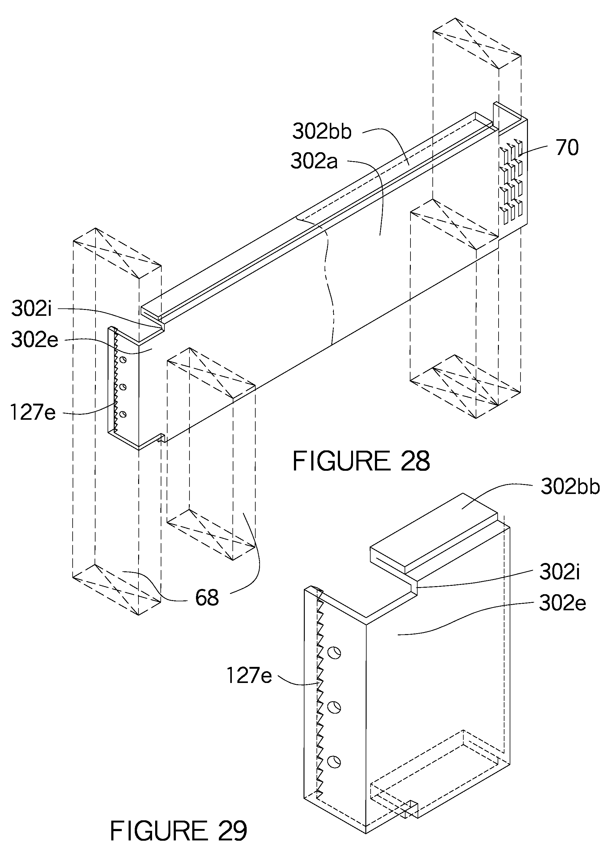
D00022

D00023

D00024

D00025

D00026

D00027

D00028
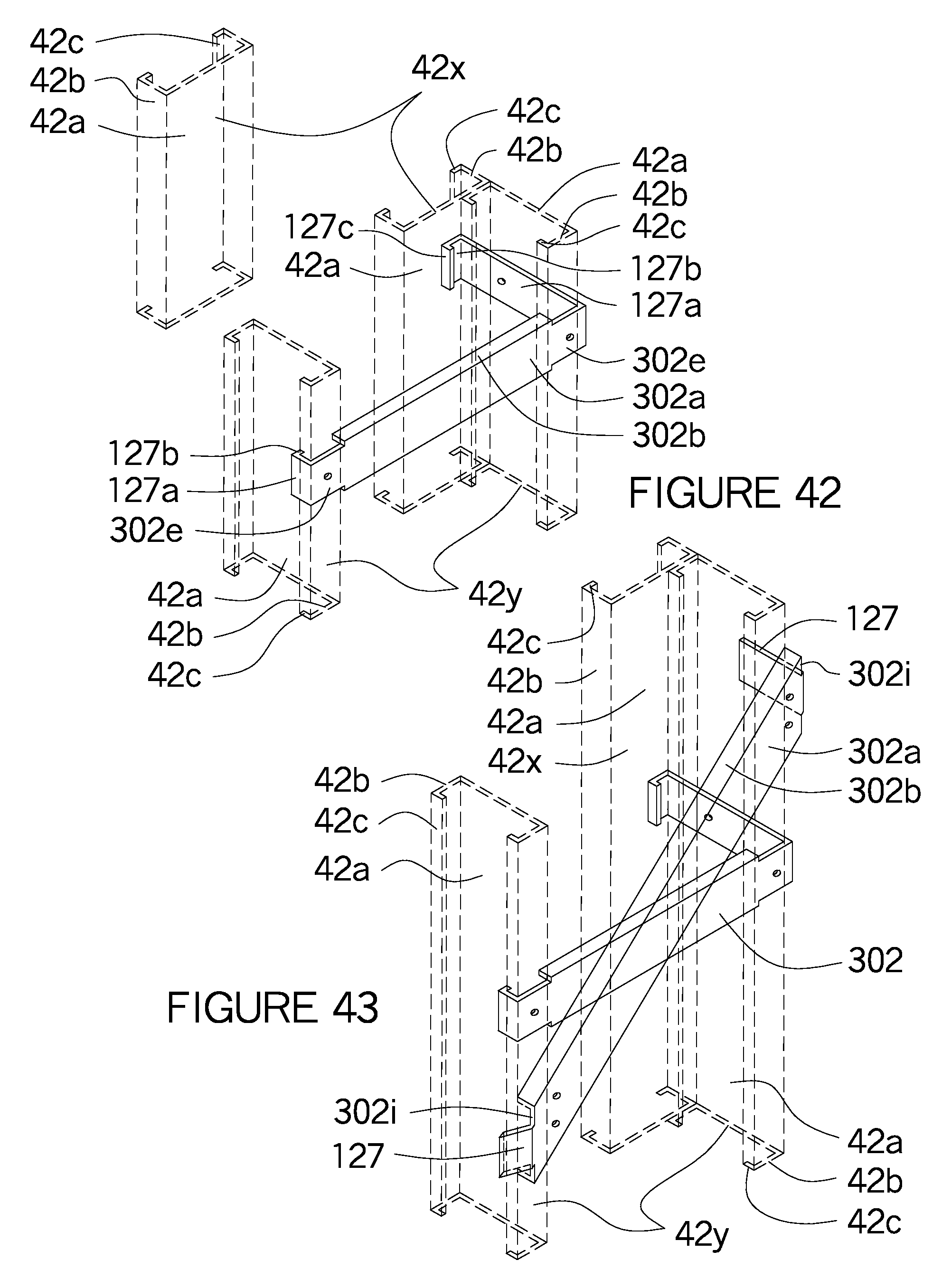
D00029

D00030

D00031
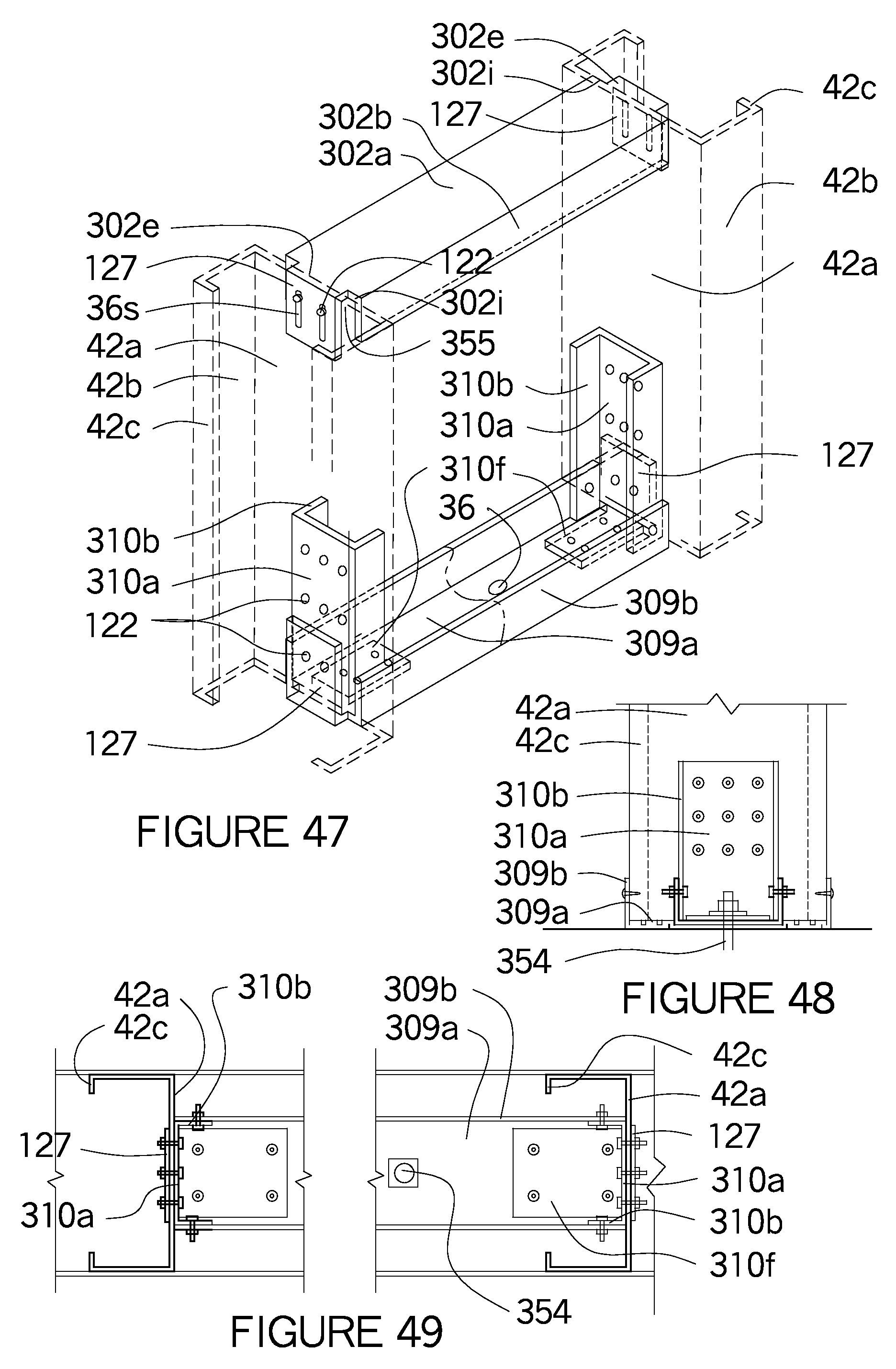
D00032

D00033

D00034
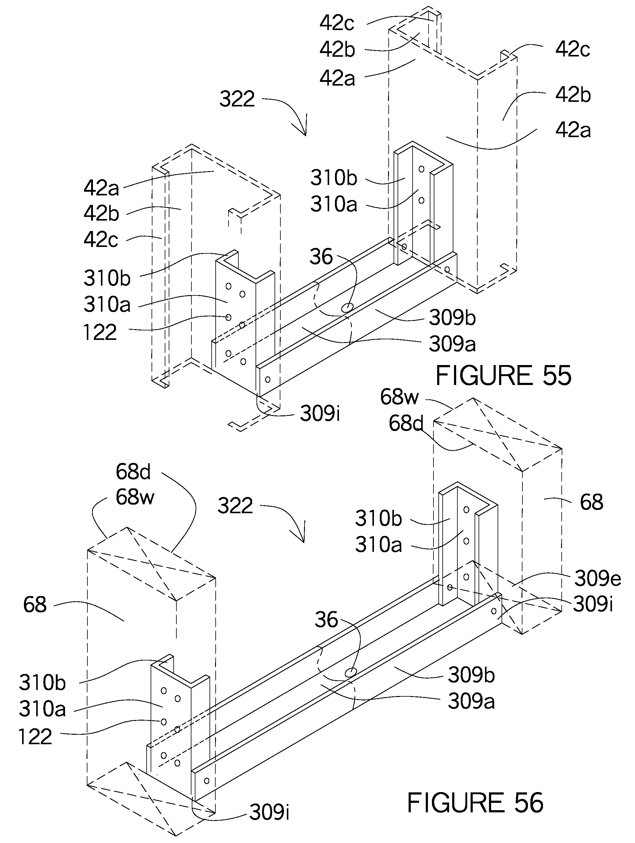
D00035

XML
uspto.report is an independent third-party trademark research tool that is not affiliated, endorsed, or sponsored by the United States Patent and Trademark Office (USPTO) or any other governmental organization. The information provided by uspto.report is based on publicly available data at the time of writing and is intended for informational purposes only.
While we strive to provide accurate and up-to-date information, we do not guarantee the accuracy, completeness, reliability, or suitability of the information displayed on this site. The use of this site is at your own risk. Any reliance you place on such information is therefore strictly at your own risk.
All official trademark data, including owner information, should be verified by visiting the official USPTO website at www.uspto.gov. This site is not intended to replace professional legal advice and should not be used as a substitute for consulting with a legal professional who is knowledgeable about trademark law.