Sheet Conveying Apparatus And Image Forming System
TERAO; Yasunobu
U.S. patent application number 16/209770 was filed with the patent office on 2019-08-08 for sheet conveying apparatus and image forming system. The applicant listed for this patent is TOSHIBA TEC KABUSHIKI KAISHA. Invention is credited to Yasunobu TERAO.
| Application Number | 20190241384 16/209770 |
| Document ID | / |
| Family ID | 67476431 |
| Filed Date | 2019-08-08 |


View All Diagrams
| United States Patent Application | 20190241384 |
| Kind Code | A1 |
| TERAO; Yasunobu | August 8, 2019 |
SHEET CONVEYING APPARATUS AND IMAGE FORMING SYSTEM
Abstract
According to an embodiment, a sheet conveying apparatus includes a roller conveying mechanism, a sheet conveying sensor, an aligning mechanism, and a conveying controller. The conveying controller causes the paper feed roller of the roller conveying mechanism to be driven to convey the sheet. Furthermore, the conveying controller causes the adjustment roller of the aligning mechanism to be driven on the basis of a detection output of the sheet conveying sensor such that a deviation between the course of the sheet and a predetermined standard course is corrected.
| Inventors: | TERAO; Yasunobu; (Izunokuni Shizuoka, JP) | ||||||||||
| Applicant: |
|
||||||||||
|---|---|---|---|---|---|---|---|---|---|---|---|
| Family ID: | 67476431 | ||||||||||
| Appl. No.: | 16/209770 | ||||||||||
| Filed: | December 4, 2018 |
| Current U.S. Class: | 1/1 |
| Current CPC Class: | B65H 7/10 20130101; B65H 9/006 20130101; B65H 2404/1441 20130101; B65H 2801/06 20130101; B65H 2511/242 20130101; B65H 9/002 20130101; B65H 2301/3613 20130101; B65H 5/062 20130101; B65H 2404/1424 20130101; B65H 7/06 20130101 |
| International Class: | B65H 9/00 20060101 B65H009/00; B65H 5/06 20060101 B65H005/06 |
Foreign Application Data
| Date | Code | Application Number |
|---|---|---|
| Feb 8, 2018 | JP | 2018-021388 |
Claims
1. A sheet conveying apparatus, comprising: a roller conveying mechanism that conveys a sheet by causing the sheet to come in contact with at least one paper feed roller; a sheet conveying sensor that detects a course of the sheet conveyed by the roller conveying mechanism; an aligning mechanism that has at least one adjustment roller, the adjustment roller correcting the course of the sheet, conveying the sheet, and aligning an edge position of the sheet; and a conveying controller configured to cause the paper feed roller of the roller conveying mechanism to be driven to convey the sheet, and cause the adjustment roller of the aligning mechanism to be driven on the basis of a detection output of the sheet conveying sensor such that a deviation between the course of the sheet and a predetermined standard course is corrected.
2. The sheet conveying apparatus according to claim 1, wherein the adjustment roller includes a course correcting roller that corrects the course of the sheet conveyed by the paper feed roller and conveys the sheet, and a resist roller that aligns the edge position of the sheet conveyed by the course correcting roller.
3. The sheet conveying apparatus according to claim 2, further comprising: a first contact/separate mechanism that selectively switches a state of the course correcting roller between a first state that the course correcting roller presses the sheet and a second state that the course correcting roller does not press the sheet.
4. The sheet conveying apparatus according to claim 3, wherein the conveying controller is configured to cause the first contact/separate mechanism to switch the state of the course correcting roller to the first state, and cause the first contact/separate mechanism to switch the state of the course correcting roller to the second state after the edge of the sheet conveyed by the course correcting roller in the first state is nipped between the course correcting roller and the resist roller.
5. The sheet conveying apparatus according to claim 4, wherein the first contact/separate mechanism selectively switches between the first state that the course correcting roller presses the sheet and the second state that the course correcting roller does not press the sheet on the basis of a control signal from the conveying controller.
6. The sheet conveying apparatus according to claim 1, further comprising: a second contact/separate mechanism that selectively switches a state of the paper feed roller between a third state that the paper feed roller presses the sheet and a fourth state that the paper feed roller does not press the sheet.
7. The sheet conveying apparatus according to claim 6, wherein the conveying controller is configured to cause the second contact/separate mechanism to switch the state of the paper feed roller to the third state, and cause the second contact/separate mechanism to switch the state of the paper feed roller to the fourth state after the edge of the sheet conveyed by the paper feed roller in the third state arrives at the aligning mechanism.
8. The sheet conveying apparatus according to claim 7, wherein the second contact/separate mechanism selectively switches between the third state that the paper feed roller presses the sheet and the fourth state that the paper feed roller does not press the sheet on the basis of the control signal from the conveying controller.
9. An image forming system, comprising: a printer that forms an image on a sheet; and a sheet conveying apparatus that conveys the sheet to the printer, the sheet conveying apparatus including a roller conveying mechanism that conveys a sheet by causing the sheet to come in contact with at least one paper feed roller, a sheet conveying sensor that detects a course of the sheet conveyed by the roller conveying mechanism, an aligning mechanism that has at least one adjustment roller, the adjustment roller correcting the course of the sheet, conveying the sheet, and aligning an edge position of the sheet, and a conveying controller configured to cause the paper feed roller of the roller conveying mechanism to be driven to convey the sheet, and cause the adjustment roller of the aligning mechanism to be driven on the basis of a detection output of the sheet conveying sensor such that a deviation between the course of the sheet and a predetermined standard course is corrected.
10. The image forming system according to claim 9, wherein the adjustment roller includes a course correcting roller that corrects the course of the sheet conveyed by the paper feed roller and conveys the sheet, and a resist roller that aligns the edge position of the sheet conveyed by the course correcting roller.
Description
CROSS-REFERENCE TO RELATED APPLICATIONS
[0001] This application is based upon and claims the benefit of priority from the prior Japanese Patent Application No. 2018-021388, filed on Feb. 8, 2018, the entire contents of which are incorporated herein by reference.
FIELD
[0002] An embodiment to be described here generally relates to a sheet conveying apparatus and an image forming system.
BACKGROUND
[0003] For example, an image forming system has a sheet conveying apparatus such as an original document conveying apparatus, an automatic paper feeding apparatus, and a manual feeding paper feeding apparatus. The sheet conveying apparatus has guide fences for feeding sheets in a predetermined conveying direction. The sheets are aligned by the guide fences in the conveying direction. After the sheets are aligned, the sheet conveying apparatus starts to feed the sheets. However, if the sheets get out from the guide fences of the sheet conveying apparatus, a sheet course (conveying direction) may be changed. For example, if the conveying direction of conveying rollers is tilted in latter parts of the guide fences with respect to the conveying direction of the aligned sheets, the conveying direction of the sheets is tilted. If conveyance resistance of a conveying path of the sheets varies in a direction orthogonal to the conveying direction of the sheets, the sheet course is curved. The sheet conveying apparatus has a resist mechanism. Even if the sheets skew during conveyance, edge positions of the sheets are aligned by the resist mechanism. However, skewed sheets may be twisted between the resist mechanism and a paper feeding mechanism. Twisting of the sheets may cause creases. Furthermore, the resist mechanism cannot correct horizontal deviation of the sheets in the direction orthogonal to a sheet conveying direction.
BRIEF DESCRIPTION OF THE DRAWINGS
[0004] FIG. 1 is a cross-sectional view schematically showing a configuration example of an image forming system according to an embodiment.
[0005] FIG. 2 is a perspective view schematically showing a configuration example of a manual paper feeding device of a sheet conveying apparatus according to the embodiment.
[0006] FIG. 3 is a cross-sectional view schematically showing a configuration example of a manual paper feeding device and peripherals of the sheet conveying apparatus according to the embodiment.
[0007] FIG. 4 is a perspective view schematically showing a configuration example of a roller conveying mechanism and peripherals of the sheet conveying apparatus according to the embodiment.
[0008] FIG. 5A is a view schematically showing a configuration example of main parts of a second contact/separate mechanism of the sheet conveying apparatus according to the embodiment.
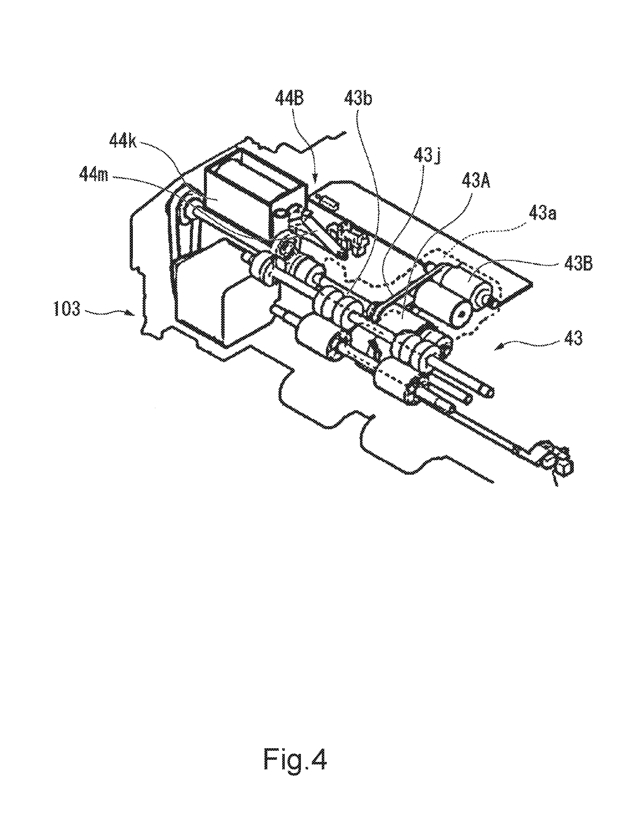
[0009] FIG. 5B is a view schematically showing a configuration example of main parts of a second contact/separate mechanism of the sheet conveying apparatus according to the embodiment.
[0010] FIG. 6A is a plan view showing a configuration example of a course correcting unit of the sheet conveying apparatus according to the embodiment.
[0011] FIG. 6B is a sectional view taken along A-A of FIG. 6A showing course correcting rollers of the sheet conveying apparatus according to the embodiment.
[0012] FIG. 7A is a view schematically showing a configuration example of main parts of a first contact/separate mechanism of the sheet conveying apparatus according to the embodiment.
[0013] FIG. 7B is a view schematically showing a configuration example of main parts of a first contact/separate mechanism of the sheet conveying apparatus according to the embodiment.
[0014] FIG. 8 is a block diagram showing a configuration example of a control system of the sheet conveying apparatus according to the embodiment.
[0015] FIG. 9 is a flowchart showing control actions of the sheet conveying apparatus according to the embodiment.
[0016] FIG. 10 is a view for describing actions of the sheet conveying apparatus according to the embodiment.
[0017] FIG. 11 is a view for describing actions of the sheet conveying apparatus according to the embodiment.
[0018] FIG. 12 is a view for describing actions of the sheet conveying apparatus according to the embodiment.
[0019] FIG. 13 is a view for describing actions of the sheet conveying apparatus according to the embodiment.
[0020] FIG. 14 is a view for describing actions of the sheet conveying apparatus according to the embodiment.
[0021] FIG. 15 is a view for describing actions of the sheet conveying apparatus according to the embodiment.
DETAILED DESCRIPTION
[0022] According to an embodiment, a sheet conveying apparatus includes a roller conveying mechanism, a sheet conveying sensor, an aligning mechanism, and a conveying controller. The roller conveying mechanism conveys the sheet by causing the sheet to come in contact with at least one paper feed roller. The sheet conveying sensor detects a course of the sheet conveyed by the roller conveying mechanism. The aligning mechanism has at least one adjustment roller that corrects the course of the sheet, conveys the sheet, and aligns an edge position of the sheet. The conveying controller causes the paper feed roller of the roller conveying mechanism to be driven to convey the sheet. Furthermore, the conveying controller causes the adjustment roller of the aligning mechanism to be driven on the basis of a detection output of the sheet conveying sensor such that a deviation between the course of the sheet and a predetermined standard course is corrected.
[0023] Hereinafter, the sheet conveying apparatus and the image forming system according to an embodiment will be described with reference to the drawings. In the drawings, the same symbols denote the same or similar parts. FIG. 1 schematically shows a configuration example of an image forming system 100 including sheet conveying apparatuses 1, 2, 3 according to the embodiment. FIG. 2 schematically shows a configuration example of a manual paper feeding device 106 of the sheet conveying apparatus 1 according to the embodiment. FIG. 3 schematically shows a configuration example of a manual paper feeding device 106 and peripherals. FIG. 4 schematically shows a configuration example of a roller conveying mechanism 43 and peripherals of the sheet conveying apparatus 1 according to the embodiment. FIG. 5A and FIG. 5B schematically show a configuration example of main parts of a second contact/separate mechanism 44A. FIG. 6A shows a configuration example of a course correcting unit 46 of the sheet conveying apparatus 1 according to the embodiment. FIG. 6B is a sectional view taken along A-A of FIG. 6A and shows course correcting rollers 46A and 46B of the course correcting unit 46. FIG. 7A and FIG. 7B schematically show a configuration example of main parts of a first contact/separate mechanism 48 of the sheet conveying apparatus 1 according to the embodiment. In the above-mentioned drawings, the size and the shape of each member are exaggerated or simplified for ease of view (the same applies to the following drawings).
[0024] The image forming system 100 according to the embodiment shown in FIG. 1 is, for example, an MFP (Multi-Function Peripherals). The image forming system 100 may be a printer, a copy machine, or the like. The image forming system 100 includes a scanner 101, an ADF (Auto Document feeder) 102, a printer 103, a paper feeding device 104, an inverting device 105, a manual paper feeding device 106, and a controller 110. Note that, in the following description, the configuration of the image forming system 100 will be described on the basis of an arrangement position of FIG. 1. The image forming system 100 of FIG. 1 is arranged on a horizontal plane. The longitudinal direction of FIG. 1 corresponds to the vertical direction. In the image forming system 100 of FIG. 1, a front part of the system corresponds to a front of FIG. 1. Viewed from the direction facing to the front part of the image forming system 100, the right side shown corresponds to the right side of the image forming system 10. Viewed from the direction facing to the front part of the image forming system 100, the left side shown corresponds to the left side of the image forming system 100. In the image forming system 100 of FIG. 1, a back part of the system faces to the back side of FIG. 1. In the following description, unless otherwise specified, in relation to relative positions of the members forming the image forming system 100, terms of "front", "back", "up", "down", "left", "right", and the like are used on the basis of the arrangement position of the above-described image forming system 100 of FIG. 1. Accordingly, the terms of "front", "back", "up", "down", "left", "right", and the like in the following description may be different from the shown positional relationship in FIG. 1.
[0025] The scanner 101 reads an original document (not shown). At the top of the scanner 101, there is an original document plate 101a on which the original document is placed. On the original document plate 101a, an ADF 102 is provided. The ADF 102 conveys the original document placed on an original document placing tray 102a to an original document reading position (not shown) of the scanner 101. After the original document is conveyed to the original document reading position, the original document is ejected to an original document discharging plate 102b located downward the original document placing tray 102a.
[0026] The scanner 101 includes an illumination light source (not shown) that illuminates the original document and an image sensor (not shown) that photoelectrically converts reflected light from the original document. The scanner 101 reads information of the original document fed to the original document reading position by the ADF 102 or the original document placed on the original document plate 101a using the illumination light source and the image sensor. Though not shown, at a front of the scanner 101 in the drawing, there is provided an operation device (operation unit) by which an operator operates actions of the image forming system 100. For example, the operation device has an operation panel including a variety of keys or a touch panel type display.
[0027] Downward the scanner 101, a printer 103 (image forming system body) and a paper feeding device 104 are provided in this order. The paper feeding device 104 feeds sheets P to be imaged to the printer 103. A direction of the sheets P moving within a paper feeding cassette 104a described later in order to feed the sheets P to the printer 103 by the paper feeding device 104 is referred to as a "first paper feeding direction" in the following description. In the example of FIG. 1, the first paper feeding direction is a direction from the left side to the right side in the drawing. A direction orthogonal to the first paper feeding direction in a sheet plane of each sheet P is referred to as a first paper feeding orthogonal direction in the following description. The paper feeding device 104 has the paper feeding cassette 104a. The paper feeding device 104 of FIG. 1 is provided with one paper feeding cassette 104a as an example. However, the paper feeding device 104 may be provided with a plurality of the paper feeding cassettes 104a. The paper feeding cassette 104a is capable of holding a variety of sizes of the sheets P. In addition, the paper feeding cassette 104a holds the sheets P on a center basis. In other words, the sheets P are held in the paper feeding cassette 104a such that a center axis line in a width of each sheet in the first paper feeding orthogonal direction is aligned at a fixed position. Furthermore, the paper feeding device 104 has a paper feed roller 104b. The paper feed roller 104b moves the sheet P to the first paper feeding direction in the paper feeding cassette 104a and feeds the sheet P from the paper feeding cassette 104a to a conveying path of the printer 103. At this time, the paper feeding device 104 feeds the sheets P one by one separately. A method of feeding the sheets P by the paper feeding device 104 is not especially limited as long as the sheets P are fed by a roller paper feeding system. Similarly, a method of separating the sheets P is not especially limited. As the method of separating the sheets P, an appropriate separation system such as a corner pawl system, a separation pad system, and a separation roller system may be used, for example. The paper feeding device 104 includes a variety of rollers, pad members, and the like other than the paper feed roller 104b corresponding to the paper feeding system and the separation system.
[0028] The printer 103 forms images on the sheets P on the basis of image data of the original document read by the scanner 101 or image data generated by a personal computer or the like. The printer 103 is a color printer, for example, in a so-called tandem system. The printer 103 includes an image forming device 30, a conveying device 40, a fuser 50, and paper ejection rollers 60.
[0029] The image forming device 30 forms the images on the sheet P by using toner having a color of yellow (Y), magenta (M), cyan (C), or black (K). The image forming device 30 includes an exposure unit 31, imaging units 32, and a transfer unit 33.
[0030] The exposure unit 31 generates light 31a for exposing a photoreceptor drum 32A (hereinafter referred to as exposing light 31a). The exposing light 31a forms an electrostatic latent image corresponding to the image of the above-described each color on the photoreceptor drum 32A included in each of four imaging units 32 described later. As the exposure unit 31, an exposure unit that scans the photoreceptor drum 32A by using laser light from a semiconductor laser device may be used. As the exposure unit 31, an exposure unit including a solid scanning device such as an LED instead of the semiconductor laser device.
[0031] Each of the four imaging units 32 includes one image carrying body, i.e., the photoreceptor drum 32A. The respective photoreceptor drums 32A are separated each other from the left side to the right side and arranged in parallel in FIG. 1. Each photoreceptor drum 32A is rotary driven clockwise as shown by using a drive motor (not shown). Each imaging unit 32 includes a charger 32B, a developing unit 32C, and a photoreceptor cleaner 32E at each outer periphery of the photoreceptor drum 32A. The charger 32B, the developing unit 32C, and the photoreceptor cleaner 32E are arranged in this order in a rotational direction of each photoreceptor drum 32A. The imaging units 32 are arranged upward the exposure unit 31. On the four photoreceptor drums 32A, the electrostatic latent images corresponding to the respective colors of Y, M, C, and K from the left side to the right side are formed. Thereafter, toner images corresponding to the electrostatic latent images are formed. Each charger 32B, each developing unit 32C, and each photoreceptor cleaner 32E in each imaging unit 32 have the same configuration except that the color of the toner used for imaging is different.
[0032] The charger 32B uniformly charges the surface of the photoreceptor drum 32A. The exposure unit 31 irradiates the exposing light 31a modulated on the basis of the image data onto the charged photoreceptor drum 32A. On the photoreceptor drum 32A, the electrostatic latent image is formed.
[0033] Each developing unit 32C includes a developing roller. The developing unit 32C charges the toner therein. A developing bias is applied to the developing roller. The developing unit 32C feeds the charged toner to the surface of the photoreceptor drum 32A using the developing roller. Once the toner is fed to the surface of the photoreceptor drum 32A, the electrostatic latent image on the photoreceptor drum 32A is developed with the toner. Each toner cartridge 32F is arranged upward each developing unit 32C via each transfer unit 33 described later. According to this embodiment, four toner cartridges 32F feeding toner having respective colors of Y, M, C, and K are arranged. Between each toner cartridge 32F and each developing unit 32C, a toner dispenser (not shown) is arranged. The toner in each toner cartridge 32F is fed to each developing unit 32C by the toner dispenser.
[0034] Each photoreceptor cleaner 32E removes the toner not primary transferred by a transfer unit 33 described later and remained on the photoreceptor drum 32A from the surface of the photoreceptor drum 32A. For example, the photoreceptor cleaner 32E has a cleaning blade that comes in contact with the photoreceptor drum 32A. The cleaning blade removes the toner remained on the surface of the photoreceptor drum 32A.
[0035] The transfer unit 33 is arranged upward each photoreceptor drum 32A facing to each photoreceptor drum 32A. The transfer unit 33 sequentially transfers each toner image formed on the surface of each photoreceptor drum 32A to an intermediate transfer belt 33A described later (primary transfer). By the primary transfer, the toner image of each color (primary transferred image) is formed on the intermediate transfer belt 33A. Furthermore, transfer unit 33 transfers the primary transferred image on the sheet P (secondary transfer). By the secondary transfer, the toner image is formed on the sheet P. The transfer unit 33 includes the intermediate transfer belt 33A, a drive roller 33B, an idler roller 33C, a primary transfer roller 33D, a secondary transfer roller 33E, and an intermediate transfer belt cleaner 33F.
[0036] The intermediate transfer belt 33A is horizontally stretched in the left and right directions by the drive roller 33B and a plurality of idler rollers 33C in FIG. 1. The drive roller 33B is rotary driven counterclockwise as shown by using a drive motor (not shown). When the drive roller 33B is driven, the intermediate transfer belt 33A endlessly travels counterclockwise as shown. A linear speed of the intermediate transfer belt 33A is controlled corresponding to a speed (process speed) of forming the toner image on the photoreceptor drum 32A. The process speed is set in advance. The lower surface of the intermediate transfer belt 33A shown is in contact with the upper surface of each photoreceptor drum 32A.
[0037] Inside the intermediate transfer belt 33A, each primary transfer roller 33D is arranged at the position facing to each photoreceptor drum 32A. When a voltage for the primary transfer is applied, the primary transfer roller 33D performs the primary transfer of the toner image on each photoreceptor drum 32A to the intermediate transfer belt 33A.
[0038] The secondary transfer roller 33E is arranged facing to the drive roller 33B via the intermediate transfer belt 33A. The contact position between the secondary transfer roller 33E and the intermediate transfer belt 33A is a secondary transfer position where the toner image is transferred (secondary transfer) from the intermediate transfer belt 33A to the sheet P. A secondary transfer voltage is applied to the secondary transfer roller 33E at the secondary transfer position, when the sheet P passes between the drive roller 33B and the secondary transfer roller 33E. When the secondary transfer voltage is applied, the secondary transfer roller 33E performs the secondary transfer of the toner image of the intermediate transfer belt 33A on the sheet P.
[0039] At the position near the idler roller 33C shown at the left end of the drawing, an intermediate transfer belt cleaner 33F is arranged. The intermediate transfer belt cleaner 33F removes the toner that is not secondary transferred to the sheet P and remained on the intermediate transfer belt 33A from the intermediate transfer belt 33A. For example, the intermediate transfer belt cleaner 33F includes a cleaning blade being in contact with the intermediate transfer belt 33A. The cleaning blade removes the toner remained on the surface of the intermediate transfer belt 33A.
[0040] The conveying device 40 conveys the sheet P fed from the paper feeding cassette 104a in the first conveying direction (direction from the lower side to the upper side as shown) along a first conveying path 41 of the printer 103. The first conveying path 41 includes a plurality of conveying guide members. The first conveying path 41 guides conveyance of the sheet P. The first conveying path 41 is arranged between the position of the paper feed roller 104b and the above-described secondary transfer positon, between the secondary transfer position and a position of the fuser 50 described later, and between the position of the fuser 50 and positions of the paper ejection rollers 60 described later.
[0041] The conveying device 40 further includes an aligning mechanism 42. The aligning mechanism 42 is arranged at the first conveying path 41 between the position of the paper feed roller 104b and the secondary transfer position. The aligning mechanism 42 includes at least one adjustment roller driven by a drive motor (not shown). The adjustment roller corrects the course of the sheet P on the basis of detection outputs of sheet conveying sensors 47 described later. The adjustment roller aligns the edge position of the sheet P. In a case where the aligning mechanism 42 includes a plurality of adjustment rollers, the adjustment rollers may include course correcting rollers (first and second course correcting rollers 46A and 46B) and resist roller 45s. The course correcting rollers (first and second course correcting rollers 46A and 46B) correct the course of the sheet P on the basis of the detection outputs of the sheet conveying sensors 47 described later. The resist rollers 45 align the edge position of the sheet P. In a case where the adjustment roller of the aligning mechanism 42 is rotary-driven by the drive motor (not shown), the adjustment roller conveys the sheet P in the first conveying direction. A linear speed of the adjustment roller is controlled so as to synchronize with the linear speed of the intermediate transfer belt 33A. In other words, the linear speed of the adjustment roller is controlled such that the toner image formed on the intermediate transfer belt 33A and the edge of the sheet P are synchronized with and arrive at the secondary transfer position. Note that a detailed configuration of the aligning mechanism 42 will be described after an overall configuration of the image forming system 100 is described.
[0042] The fuser 50 fuses the toner image transferred to the sheet P passing through the secondary transfer position on the sheet P. The fuser 50 is arranged upward the secondary transfer roller 33E. The fuser 50 includes a fusing member 51 and a pressing member 52. The fusing member 51 and the pressing member 52 come in contact with each other to form a nip (fusing nip). The fusing member 51 and the pressing member 52 nips the sheet P conveyed through the first conveying path 41 at the fusing nip. The fusing member 51 heats the sheet P at the fusing nip. As the fusing member 51, a tube-shaped endless belt or roller is used. A heating source of the fusing member 51 is not especially limited as long as the surface temperature of the fusing member 51 can be controlled at a fusing temperature. The pressing member 52 presses the sheet P at the fusing nip. As the pressing member 52, the tube-shaped endless belt or roller is used, for example.
[0043] At least one of the fusing member 51 and the pressing member 52 is rotary-driven by a drive motor (not shown). When the drive motor is rotated, the sheet P nipped between the fusing member 51 and the pressing member 52 is conveyed in the first conveying direction at the fusing speed corresponding to the process speed.
[0044] The paper ejection rollers 60 are arranged at the end of the first conveying path 41 upward the fuser 50. Upward the fuser 50, the first conveying path 41 is curved from the right side to the left side as the first conveying path 41 directs from the lower side to the upper side as shown. A paper ejection plate 103a is arranged at the left side of the paper ejection rollers 60 as shown, upward the image forming device 30, and downward the scanner 101.
[0045] The paper ejection rollers 60 are rotary-driven in a forward and reverse ratable manner by a drive motor (not shown). When the paper ejection rollers 60 rotate forward, the paper ejection rollers 60 convey the sheet P conveyed through the first conveying path 41 further to the paper ejection plate 103a. While the paper ejection rollers 60 continue to rotate forward, the sheet P is ejected on the paper ejection plate 103a. The paper ejection rollers 60 are a pair of rollers, for example. When the paper ejection rollers 60 rotate reverse while the sheet P enters between the pair of paper ejection rollers 60, the sheet P is conveyed from the left side to the right side along a route of the end of the first conveying path 41 (switch back). In this case, the paper ejection rollers 60 can convey the sheet P to an inverting device 105 described later.
[0046] The inverting device 105 inverses the sheet P inside out that is passed through the fuser 50 and is switch-backed, and feeds the sheet P again to the aligning mechanism 42. The inverting device 105 is used for double-sided printing. The inverting device 105 is arranged at the position (right side as shown) facing to the image forming device 30 via the first conveying path 41. The inverting device 105 has a second conveying path 71. The second conveying path 71 includes a plurality of conveying guide members. The second conveying path 71 guides conveyance of the sheet P. The second conveying path 71 is branched from the first conveying path at the position between the fuser 50 and the paper ejection rollers 60. At the branched position of the first conveying path 41 and the second conveying path 71, a conveying path switching unit 72 is arranged. The conveying path switching unit 72 has a conveying path switching member 73 that guides the sheet P from the first conveying path 41 to the second conveying path 71 upon the reverse rotation of the paper ejection rollers 60. The second conveying path 71 merges with the first conveying path 41 at a merge position between the paper feeding device 104 and the aligning mechanism 42.
[0047] The second conveying path 71 includes a plurality of inversing conveying rollers driven by a drive motor (not shown). Each inversing conveying roller conveys the sheet P in the second conveying direction. The second conveying direction directs from the paper ejection rollers 60 to the conveying path switching unit 72 via the first conveying path 41 and from the conveying path switching unit 72 to the merge position 74 via the second conveying path 71. The sheet P conveyed from the merge position 74 to the first conveying path 41 is conveyed in the first conveying direction of the first conveying path 41.
[0048] The manual paper feeding device 106 feeds the sheets P for image formation set manually as appropriate to the printer 103. In the following description, the direction to which the sheets P are moved for feeding the sheets P to printer 103 by the manual paper feeding device 106 is referred to as a second paper feeding direction. In the example of FIG. 1, the second paper feeding direction is the direction from the right side to the left side as shown. In the following description, the direction orthogonal to the second paper feeding direction in the sheet plane of the sheets P is referred to as a second paper feeding orthogonal direction.
[0049] The manual paper feeding device 106 has a manual paper feeding tray 106a and manual feeding guides 106b. The manual paper feeding tray 106a is revolvably arranged making an axis of rotation extending in the second paper feeding orthogonal direction as the center. In a case where the manual paper feeding device 106 is used, the manual paper feeding tray 106a is revolved in the arrow direction as shown (clockwise direction) and is held at the position protruding from a side of a housing of the image forming system 100 (position shown in FIG. 1). In a case where the manual paper feeding device 106 is not used, the manual feeding paper feeding tray 106a is housed in the side of the housing of the image forming system 100 at the position overlapping with the inverting device 105 (position shown by a long dashed double dotted line in FIG. 1). The manual feeding guides 106b include wall-shaped members extending in the second paper feeding direction in parallel with and facing to the second paper feeding orthogonal direction with respect to each other. The manual feeding guides 106b are arranged such that each sheet P set on the manual feeding paper feeding tray 106a is nipped therebetween in the second paper feeding orthogonal direction. The manual feeding guides 106b are slide-movable in the second paper feeding orthogonal direction corresponding to a size of the sheet set on the manual feeding paper feeding tray 106a. The manual feeding guide 106b aligns each sheet P having a certain size on a center basis on the manual feeding paper feeding tray 106a. In other words, the sheets P are set on the manual feeding paper feeding tray 106a by the manual feeding guide 106b such that the center axis line of the width of each sheet P in the second paper feeding orthogonal direction is aligned with a fixed position.
[0050] The manual paper feeding device 106 has a roller conveying mechanism 43. The roller conveying mechanism 43 separates the sheets P one by one from the manual feeding paper feeding tray 106a and feeds the sheet P to the first conveying path 41. The method of feeding the sheets P by the roller conveying mechanism 43 is not especially limited as long as it is the roller paper feeding method. Similarly, the method of separating the sheets P by the roller conveying mechanism 43 is also not especially limited. Examples of the method of separating the sheets P include an appropriate separation method such as a separation pad system, a separation roller system, and the like. FIG. 1 shows the separation roller system as an example. The roller conveying mechanism 43 has a variety of rollers, pad members, or the like corresponding to the paper feeding system and the separation system. A detailed configuration of the roller conveying mechanism 43 will be described after the overall configuration of the image forming system 100 is described.
[0051] The controller 110 controls actions of each device of the image forming system 100 on the basis of an operation input from the operation device (not shown). For example, the controller 110 has a CPU, a read only memory (ROM), a random access memory (RAM), an input-output interface, an input-output control circuit, a paper feeding/conveying control circuit, an image forming control circuit, and a fusing control circuit. The CPU realizes a processing function for image formation by executing a program stored in the ROM or the RAM. The input-output control circuit of the controller 110 controls the operation device and a display device. As the operation device, an operation panel including a key board, a display, and the like may be used. As the display device, a display displaying an image, character information, and the like may be used. The paper feeding/conveying control circuit drive-controls the paper feeding device 104, the inverting device 105, the printer 103, the paper ejection rollers 60, and a variety of drive motors included in the inverting device 105. The image forming control circuit controls actions of the ADF 102, the scanner 101, and the image forming device 30 on the basis of a control signal from the CPU. The fusing control circuit controls actions of the drive motor of the fuser 50 and the temperature of the fusing member 51 on the basis of the control signal from the CPU. A paper feeding control by the controller 110 will be described later.
[0052] The image forming system 100 includes the sheet conveying apparatuses 1, 2, 3 according to this embodiment. The sheet conveying apparatus 1 according to this embodiment includes the manual paper feeding device 106, the aligning mechanism 42, the sheet conveying sensors 47 described later, and the controller 110. The sheet conveying apparatus 2 according to this embodiment includes the paper feeding device 104, the aligning mechanism 42, the sheet conveying sensors 47, and the controller 110. The sheet conveying apparatus 3 according to this embodiment includes the inverting device 105, the aligning mechanism 42, the sheet conveying sensors 47, and the controller 110. Hereinafter, a detailed configuration of the sheet conveying apparatus 1 will be mainly described.
[0053] As shown in FIGS. 2 to 4, the roller conveying mechanism of the manual paper feeding device 106 has a pick-up roller 43B, a paper feed roller 43A, and a separation roller 43C. The pick-up roller 43B is arranged upward an edge of the manual feeding paper feeding tray 106a. The pick-up roller 43B rotates in conjunction with the rotation of the paper feed roller 43A described later. The pick-up roller 43B includes a one-way clutch inside so as not to rotate in the direction opposite to a rotational direction of the paper feed roller 43A. The pick-up roller 43B is contactable/separatable to an upper surface of the manual feeding paper feeding tray 106a by a third contact/separate mechanism 44B (see FIG. 5A and FIG. 5B) descried later. The pick-up roller 43B takes out the sheet P (see FIG. 2) set on the manual feeding paper feeding tray 106a. The pick-up roller 43B conveys the taken-out sheet P in the second paper feeding direction toward the paper feed roller 43A.
[0054] The paper feed roller 43A is arranged in line with the pick-up roller 43B at the position toward the second paper feeding direction with respect to the pick-up roller 43B (e.g., left side in FIG. 3). The paper feed roller 43A is fixed to the axis of rotation 43b. The axis of rotation 43b is revolvably fixed to a body of the printer 103 by a bearing (not shown). The axis of rotation 43b is connected to a paper feed roller drive motor (not shown). The paper feed roller drive motor rotary-drives the axis of rotation 43b. A pick-up arm 43a is connected to the axis of rotation 43b. The pick-up arm 43a is revolvable around the center axis line of the axis of rotation 43b. The pick-up arm 43a rotatably supports the pick-up roller 43B around the center axis line. As shown in FIG. 4, belt pulleys are provided to the paper feed roller 43A and the pick-up roller 43B, respectively. A belt 43j is turned around the belt pulleys. The pick-up roller 43B rotates in conjunction with the paper feed roller 43A with the belt 43j in the same direction as the paper feed roller 43A.
[0055] A configuration of the third contact/separate mechanism 44B is not especially limited as long as the pick-up roller 43B is contactable/separatable to the manual feeding paper feeding tray 106a and the sheets P on the manual feeding paper feeding tray 106a. In the example shown in FIG. 5A, the third contact/separate mechanism 44B has a lever 44g, a tension spring 44m, and a solenoid 44k.
[0056] The lever 44g is revolvably supported by a revolving shaft 44h with respect to the body of the printer 103. The lever 44g is extended in different directions from the revolving shaft 44h. The lever 44g has a first end 44i and a second end 44j at edges in the extending direction. To the first end 44i, the tension spring 44m and the solenoid 44k are connected. The second end 44j is arranged at a lower side of the locking unit 43i. The second end 44j is contactable/separatable to the locking unit 43i at a lower side of the locking unit 43i. The locking unit 43i is arranged at the pick-up arm 43a or the pick-up roller 43B. The tension spring 44m pulls the first end 44i. The tension direction of the tension spring 44m is the direction where the lever 44g is revolved counterclockwise as shown by taking the revolving shaft 44h as the center. The end of the tension spring 44m opposite to the end connected to the first end 44i is fixed to the body of the printer 103. The solenoid 44k switches the state of pulling the first end 44i and the state of cancelling the pulling by turning on/off electricity. The solenoid 44k pulls the first end 44i in the direction opposite to the pulling direction of the tension spring 44m when electricity is turned on. The solenoid 44k revolves the lever 44g clockwise as shown by pulling the first end 44i against the pulling of the tension spring 44m when electricity is turned on.
[0057] FIG. 5A shows the state that the lever 44g is revolved at the maximum clockwise as shown when electricity is turned on to the solenoid 44k. In this case, the second end 44j is separated downward the locking unit 43i. The pick-up arm 43a is revolved at the maximum clockwise as shown by own weights of the pick-up arm 43a and pick-up roller 43B. The pick-up roller 43B is in contact with the manual feeding paper feeding tray 106a or the sheet P (not shown) on the manual feeding paper feeding tray 106a from the above. In contrast, FIG. 5B shows the state of the solenoid 44k when electricity is turned off. When electricity is turned off to the solenoid 44k, the lever 44g is pulled by the tension spring 44m. The lever 44g is revolved counterclockwise as shown. FIG. 5B shows the state that the lever 44g is revolved at the maximum counterclockwise as shown. In this case, the second end 44j is in contact with a lower end of the locking unit 43i downward. The pick-up arm 43a is revolved counterclockwise as shown taking the axis of rotation 43b as the center. The pick-up roller 43B is moved upward the manual feeding paper feeding tray 106a or the sheets P (not shown) on the manual feeding paper feeding tray 106a. The pick-up roller 43B is separated from the manual feeding paper feeding tray 106a or the sheets P (not shown) on the manual feeding paper feeding tray 106a.
[0058] As shown in FIG. 3, the separation roller 43C is arranged facing to the paper feed roller 43A downward the paper feed roller 43A. The separation roller 43C is contactably/separatably arranged with respect to the paper feed roller 43A and the sheet P (not shown) conveyed by the paper feed roller 43A. The separation roller 43C is connected to a paper feed roller drive motor (not shown) via a torque limiter 43f, an axis of rotation 43d, and a transmission mechanism (not shown). Note that a rotary drive direction of the separation roller 43C is the same direction as the rotational direction of the paper feed roller 43A. The torque limiter 43f is arranged so as to perform a separation action that prevents the sheets P from multiple paper feeding.
[0059] The torque limiter 43f cancels the connection to the paper feed roller drive motor with a torque based on a frictional force received from the paper feed roller 43A when the paper feed roller 43A comes in contact with the separation roller 43C. In this case, the separation roller 43C rotates in conjunction with the paper feed roller 43A in a reverse direction. The separation roller 43C adds a certain torque load to the paper feed roller 43A. The torque limiter 43f maintains the connection to the paper feed roller drive motor with the torque based on a frictional force received from the sheet P in a case where the sheet P enters between the paper feed roller 43A and the separation roller 43C. In this case, the separation roller 43C continues to rotate clockwise as shown. The frictional force from the separation roller 43C acts on the sheet P in the direction opposite to the second paper feeding direction. The frictional force from the separation roller 43C is smaller than a frictional force acted from the paper feed roller 43A to the sheet P being in contact with the paper feed roller 43A. Note that the frictional force from the separation roller 43C is greater than a frictional force between a plurality of sheets P. Accordingly, the separation roller 43C slips with respect to one sheet P being in contact with the paper feed roller 43A. In a case where a plurality of sheets P enter between the paper feed roller 43A and the separation roller 43C, the separation roller 43C pushes back the sheets P thereunder in the direction opposite to the second paper feeding direction until the number of the sheets P between the paper feed roller 43A and the separation roller 43C becomes one. By performing the separation action, the separation roller 43C prevents the sheets P from multiple paper feeding.
[0060] As shown in FIG. 5A and FIG. 5B, in this embodiment, the axis of rotation 43d of the separation roller 43C is rotatably supported by a bearing 43e fixed to a revolving arm 43h. The revolving arm 43h is revolvably fixed to a support shaft 43g arranged by a support shaft 43g arranged at the right side of the separation roller 43C. The support shaft 43g extends in parallel with the axis of rotation 43b. The support shaft 43g is fixed to the body of the printer 103. The revolving arm 43h is revolved around the support shaft 43g by a second contact/separate mechanism 44A described later. With this configuration, the separation roller 43C is contactably/separatably supported on the paper feed roller 43A. The above-described separation action is performed in a case where the separation roller 43C is in contact with the paper feed roller 43A or in a case where the separation roller 43C is in contact with the sheet P conveyed by the paper feed roller 43A.
[0061] The second contact/separate mechanism 44A is not especially limited as long as the separation roller 43C can be contacted/separated with respect to the sheet P conveyed by the paper feed roller 43A and the paper feed roller 43A. In the example shown in FIG. 5A, the second contact/separate mechanism 44A has the configuration substantially similar to that of the third contact/separate mechanism 44B. The second contact/separate mechanism 44A has a lever 44a, a tension spring 44f, and a solenoid 44e.
[0062] The lever 44a is revolvably supported by a revolving shaft 44b with respect to the body of the printer 103. The lever 44a is extended in different directions from the revolving shaft 44b. The lever 44d has a first end 44c and a second end 44d at edges in the extending direction. To the first end 44c, the tension spring 44f and the solenoid 44e are connected. The second end 44d is arranged at a lower side of the bearing 43e. The second end 44d is contactable/separatable to the bearing 43e at a lower side of the bearing 43e. The tension spring 44f pulls the first end 44c. The tension direction of the tension spring 44f is the direction where the lever 44a is revolved clockwise as shown by taking the revolving shaft 44b as the center. The end of the tension spring 44f opposite to the end connected to the first end 44c is fixed to the body of the printer 103. The solenoid 44e switches the state of pulling the first end 44c and the state of cancelling the pulling by turning on/off electricity. The solenoid 44e pulls the first end 44c in the direction opposite to the pulling direction of the tension spring 44f when electricity is turned on. The solenoid 44e revolves the lever 44a counterclockwise as shown by pulling the first end 44c against the pulling of the tension spring 44f when electricity is turned on.
[0063] FIG. 5A shows the state that the lever 44a is revolved at the maximum clockwise as shown when electricity is turned off to the solenoid 44e. In this case, the lever 44a is pulled by the tension spring 44f. The second end 44d presses the bearing 43e from downward to upward. The revolving arm 43h is revolved at the maximum clockwise as shown. The separation roller 43C is in contact with the paper feed roller 43A or the sheet P (not shown) fed by the paper feed roller 43A from the lower side. In contrast, FIG. 5B shows the state of the solenoid 44e when electricity is turned on. When electricity is turned on to the solenoid 44e, the lever 44a is pulled by the solenoid 44e in the direction opposite to the pulling direction of the tension spring 44f. The lever 44a is revolved counterclockwise as shown. FIG. 5B shows the state that the lever 44g is revolved at the maximum counterclockwise as shown. In this case, the second end 44d is in contact with the bearing 43e fallen down by own weights of the revolving arm 43h and the separation roller 43C. The revolving arm 43h is revolved counterclockwise as shown taking the axis of rotation 43g as the center. The separation roller 43C is moved downward the paper feed roller 43A or the sheet P (not shown) fed by the paper feed roller 43A. The separation roller 43C is separated from the paper feed roller 43A or the sheet P (not shown) fed by the paper feed roller 43A.
[0064] As shown in FIG. 3, the aligning mechanism 42 has the resist rollers 45 (adjustment roller), pre-resist detection sensor 45s, and the course correcting unit 46. The resist rollers 45 include a first roller 45a (adjustment roller) and a second roller 45b (adjustment roller). The first roller 45a and the second roller 45b come in contact with each other to form a nip. For example, as the first roller 45a, a metal roller may be used. For example, as the second roller 45b, a rubber roller may be used. The first roller 45a and the second roller 45b are driven by a resist roller drive motor (not shown). The resist rollers 45 align the edge of the sheet P. After the edge of the sheet P is aligned, the resist rollers 45 convey the sheet P through the first conveying path 41 to the secondary transfer position.
[0065] As shown in FIG. 3, the pre-resist detection sensor 45s is arranged at the first conveying path 41 between the resist rollers 45 and the course correcting unit 46 described later. The pre-resist detection sensor 45s detects whether or not the edge of the sheet P arrives at a detection position. A length from a detection position of the pre-resist detection sensor 45s in the first conveying direction to positions of the resist rollers 45 is stored in the controller 110 in advance.
[0066] The course correcting unit 46 is arranged at the first conveying path 41 between the merge position 74 and the aligning mechanism 42. As shown in FIG. 6A and FIG. 6B, the course correcting unit 46 has a holder 46a, flanges 46h and 46s, a motor for parallel movement Mp, a drive plate 46m, a motor for revolving Mr, first course correcting rollers 46A (adjustment roller and course correcting roller), and second course correcting rollers 46B (adjustment roller and course correcting roller).
[0067] The holder 46a holds the first course correcting rollers 46A and the second course correcting rollers 46B described later. The holder 46a can move the first course correcting rollers 46A and the second course correcting rollers 46B together. As shown in FIG. 6A, the holder 46a is moved in parallel with a conveying surface of the sheet P by the motor for parallel movement Mp described later. Specifically, the holder 46a is moved in a parallel movement direction Dp along a first conveying orthogonal direction D2 orthogonal to a first conveying direction D1 in the conveying surface of the sheet P. The holder 46a rotates and moves in a revolving direction Dr in the conveying surface of the sheet P by the motor for revolving Mr described later. As shown in FIG. 6B, both ends of the holder 46a, respective side plates 46d are mounted upright. A bearing 46b is fixed to each side plate 46d. The bearing 46b rotatably supports the first course correcting rollers 46A around the center axis line. In each side plate 46d, a long slide hole 46e penetrates in the direction facing to the bearing 46b next to the bearing 46b.
[0068] Flanges 46h and 46s are arranged at a base end (upper end in FIG. 6B) of each side plate 46d. The flanges 46h and 46s extend from the both ends of the holder 46a in the longitudinal direction to downward. A flange 46h has a slide hole 46i and a rack 46j. As shown in FIG. 6A, the slide hole 46i penetrates in the thickness direction of the flange 46h. The slide hole 46i is long in the longitudinal direction of the holder 46a. A guide pin 46k fixed to the body of the printer 103 is inserted into the slide hole 46i. The rack 46j is formed in an extension direction in a side facing to the extension direction of the flange 46h. A drive force of the motor for parallel movement Mp is transmitted to the rack 46j via a transmission mechanism Gp. For example, as the transmission mechanism Gp, a gear wheel transmission mechanism having a pinion of driving the rack 46j may be used. To the body of the printer 103, a first HP detection sensor H1 is fixed. The first HP detection sensor H1 detects a home position (HP) of the flange 46h in the parallel movement direction Dp. For example, as the first HP detection sensor H1, a photo interpreter may be used.
[0069] As shown in FIG. 6A and FIG. 6B, the flange 46s has a slide hole 46r. The slide hole 46r penetrates in the thickness direction of the flange 46s. The slide hole 46r is long in the longitudinal direction of the holder 46a. The drive plate 46m is revolvably arranged in a plane parallel to the conveying surface of the sheet P taking the rotation shaft 46n as the center. A drive pin 46q is mounted upright to an upper surface of the drive plate 46m. The drive pin 46q penetrates through the slide hole 46r of the flange 46s downward. As shown in FIG. 6A, the flange 46s receives the drive force from the drive pin 46q when the drive plate 46m is revolved around the rotation shaft 46n as the center. Corresponding to an amount of movement of the drive pin 46q, the flange 46s is revolved in the revolving direction Dr. At this time, the guide pin 46k is inserted into the slide hole 46i. Accordingly, the holder 46a is revolved in the revolving direction Dr as a whole around the guide pin 46k as the center. At an outer periphery of the drive plate 46m, a gear 46p is formed.
[0070] The drive force of the motor for revolving Mr is transmitted to the gear 46p via the transmission mechanism Gr. For example, as the transmission mechanism Gr, a gear wheel transmission mechanism may be used. A second HP detection sensor H2 is fixed to the body of the printer 103. The second HP detection sensor H2 detects the HP of the flange 46s in the revolving direction Dr. For example, as the second HP detection sensor H2, the photo interpreter may be used. In this embodiment, the HP of the holder 46a is the position when the first course correcting rollers 46A and the second course correcting rollers 46B extend in the first conveying orthogonal direction D2 and the first course correcting rollers 46A and the second course correcting rollers 46B are positioned at the center of the first conveying path 41 in the first conveying orthogonal direction D2, as described later. Hereinafter, unless otherwise specified, a positional relationship among respective members of the course correcting unit 46 is described in a case where the holder 46a is in the HP as an example.
[0071] The first course correcting rollers 46A are fixed to the axis of rotation 46f. Both ends of the axis of rotation 46f are inserted into the bearing 46b fixed to each side plate 46d. The axis of rotation 46f extends in the longitudinal direction of the holder 46a. As shown in FIG. 6B, an end of the axis of rotation 46f (end at right side shown) penetrating to the side plate 46d having the flange 46h is connected to the transmission mechanism Gd via a joint 46t. The transmission mechanism Gd transmits the drive force from a course correcting roller drive motor (not shown) to the axis of rotation 46f. For example, as the transmission mechanism Gd, a gear wheel transmission mechanism may be used. The joint 46t is expandable, contractable, and revolvable along with the movement of the axis of rotation 46f if the axis of rotation 46f moves in association with a parallel movement and a revolving movement of the holder 46a. A drive gear 46u is fixed to the axis of rotation 46f between the joint 46t and the side plate 46d. The drive gear 46u transmits the drive force from the course correcting roller drive motor to the second course correcting rollers 46B.
[0072] The second course correcting rollers 46B are fixed to the axis of rotation 46g. Both ends of the axis of rotation 46g are inserted into the bearing 46c. The bearing 46c is, for example, a stepped slide bearing. As shown in FIG. 7A, a small diameter part 46w of the bearing 46c is slidably fitted to the slide hole 46e in the longitudinal direction. A large diameter part 46x of the bearing 46c is slidably locked to an outer surface of the side plate 46d. An idler gear 46v is fixed to the end (end at right side shown) of the axis of rotation 46g penetrating through the side plate 46d at the side where the flange 46h is arranged. The number of teeth of the idler gear 46v equals to the number of teeth of the drive gear 46u. The idler gear 46v is engaged with the drive gear 46u in a case where a positional relationship is such that the second course correcting rollers 46B come in contact with the first course correcting rollers 46A each other. When the idler gear 46v is engaged with the drive gear 46u, the second course correcting rollers 46B will be rotatable in the reverse direction of the first course correcting rollers 46A.
[0073] The course correcting unit 46 further includes a first contact/separate mechanism 48. The first contact/separate mechanism 48 allows the second course correcting rollers 46B to be in contact with/be separated from the first course correcting rollers 46A. The first contact/separate mechanism 48 is not especially limited as long as the second course correcting rollers 46B are contactable/separatable to the first course correcting rollers 46A. In the example shown in FIG. 7A, the first contact/separate mechanism 48 has a lever 48a, a tension spring 48f, and a solenoid 48e.
[0074] The lever 48a is revolvably supported by a revolving shaft 48b with respect to the holder 46a. The lever 48a is extended in different directions from the revolving shaft 48b. The lever 48a has a first end 48c and a second end 48d at edges in the extending direction. To the first end 48c, the tension spring 48f and the solenoid 48e are connected. The second end 48d is arranged at a lower side of the large diameter part 46x of the bearing 46c. The second end 48d is contactable/separatable to the large diameter part 46x. The tension spring 48f pulls the first end 48c. The tension direction of the tension spring 48f is the direction where the lever 48a is revolved counterclockwise as shown by taking the revolving shaft 48b as the center. The end of the tension spring 48f opposite to the end connected to the first end 48c is fixed to a fixing unit (not shown) extending from the holder 46a. The solenoid 48e switches the state of pulling the first end 48c and the state of cancelling the pulling by turning on/off electricity. The solenoid 48e pulls the first end 48c in the direction opposite to the pulling direction of the tension spring 48f when electricity is turned on. The solenoid 48e revolves the lever 48a counterclockwise as shown by pulling the first end 48c against the pulling direction of the tension spring 48f when electricity is turned on.
[0075] FIG. 7A shows the state that electricity is turned off to the solenoid 48e. When electricity is turned off to the solenoid 48e, the lever 48a is pulled by the tension spring 48f. The lever 48a is revolved clockwise as shown. FIG. 7A shows the state that the lever 48a is revolved at the maximum clockwise as shown. In this case, the second end 48d presses the large diameter part 46x of the bearing 46c from downward to upward. At this time, as shown in FIG. 6B, the first course correcting rollers 46A and the second course correcting rollers 46B are in contact with each other. The drive gear 46u and the idler gear 46v are engaged with each other on their pitch circles. In contrast, FIG. 7B shows the state of the solenoid 48e when electricity is turned on. When electricity is turned on to the solenoid 48e, the lever 48a is pulled by the solenoid 48e in the direction opposite to the pulling direction of the tension spring 48f. The lever 48a is revolved counterclockwise as shown. In this case, the second end 48d is in contact with the large diameter part 46x of the bearing 46c fallen down by own weights of the second course correcting rollers 46B. At this time, the second course correcting rollers 46B are separated from the first course correcting rollers 46A (see the long dashed double dotted line in FIG. 3).
[0076] The sheet conveying sensors 47 detect the course of the sheet P conveyed toward the resist roller 45. The course of the sheet P is represented by an amount of skew deviation with respect to a predetermined normal course and an amount of horizontal deviation. The sheet P1 shown by the long dashed double dotted line in FIG. 6A is a first size sheet P that moves in the normal course. Similarly, the sheet P 2 is a second size sheet P that moves in the normal course. Edges F of the sheets P1 and P2 extend in the first conveying orthogonal direction D2. A first side end SL and a second side end SR of the sheets P1 and P2 extend in the first conveying direction Dl. Here, the first side end SL is the side end positioned at a front side of the image forming system 100. The second side end SR is the side end positioned at a back side of the image forming system 100. The center axis lines of the sheets P1 and P2 in the first conveying orthogonal direction D2 are coincide with the center axis line C of the normal course.
[0077] The skew deviation is represented by an angle of the edge of the sheet P in the conveying direction tilted with respect to the axis line extending in the first conveying orthogonal direction. The horizontal deviation is represented by an amount of deviation between the center axis line in the standard course and a rotation center of the skew in the first conveying orthogonal direction D2 since the image forming system 100 conveys the sheet P on a center basis. Note that it is not easy to determine the rotation center during conveyance of the sheet P. In this embodiment, the amount of horizontal deviation is detected on the basis of the position of the side end of the sheet P after the skew deviation is corrected, as described later.
[0078] As shown in FIG. 3, in this embodiment, as the sheet conveying sensors 47, a skew detection sensor 47A and a horizontal deviation detection sensor 47B are arranged in the first conveying path 41. Furthermore, as the sheet conveying sensors 47, a skew detection sensor 47C and a horizontal deviation detection sensor 47D are arranged in the second conveying path 71. The skew detection sensor 47A and the horizontal deviation detection sensor 47B detect the course of the sheet P (not shown) toward the course correcting unit 46 from the inverting device 105 through the merge position 74. The detection action by the skew detection sensor 47A and the horizontal deviation detection sensor 47B and the detection action by the skew detection sensor 47C and the horizontal deviation detection sensor 47D are similar with respect to each other. Hereinbelow, the skew detection sensor 47A and the horizontal deviation detection sensor 47B are taken as an example and described.
[0079] The skew detection sensor 47A has a first skew detection sensor 47a and a second skew detection sensor 47b. The first skew detection sensor 47a and second skew detection sensor 47b are arranged at a certain distance from the nips between the first course correcting rollers 46A and the second course correcting rollers 46B in the first conveying direction D1 at the HP of the holder 46a. The first skew detection sensor 47a and the second skew detection sensor 47b are arranged to leave a space with respect to each other on the axis line extending in the first conveying orthogonal direction D2. The first skew detection sensor 47a and the second skew detection sensor 47b are arranged in line symmetry with respect to each other by the center axis line C. A distance between the first skew detection sensor 47a and the second skew detection sensor 47b is smaller than a minimum width of the sheet P to be fed.
[0080] If there are a plurality of width sizes of the sheets P fed in the first conveying orthogonal direction D2, it is desirable that the horizontal deviation detection sensor 47B have a pair of sensors for each width size. Note that a plurality kinds of the sheets P having similar sizes may be detected by a common pair of sensors. In a case where the sheets P to be fed have only one determined width size, the horizontal deviation detection sensor 47B may have only one sensor. FIG. 6A shows an example that the horizontal deviation detection sensor 47B has first horizontal deviation detection sensors 47c and 47e and second horizontal deviation detection sensors 47d and 47f. The first horizontal deviation detection sensors 47c and 47e and the second horizontal deviation detection sensors 47d and 47f are arranged apart from the skew detection sensor 47A in the direction opposite to the first conveying direction D1 and on the axis line extending in the first conveying orthogonal direction D2. The first horizontal deviation detection sensors 47c and 47e are arranged at positions corresponding to respective first side ends SL to the sheets P1 and P2 moving the standard courses, respectively. The second horizontal deviation detection sensors 47d and 47f are arranged at positions corresponding to respective second side ends SR to the sheets P1 and P2 moving the standard courses, respectively.
[0081] The skew detection sensor 47A is not especially limited as long as arrival of the edge F of the sheet P on sensor arrangement positions is detectable. Examples of the skew detection sensor 47A include a reflection type or transmission type photo sensor, a line sensor, a CCD, and the like. The horizontal deviation detection sensor 47B is not especially limited as long as arrival of the first side end SL or the second side end SR of the sheet P on sensor arrangement positions is detectable. Examples of the horizontal deviation detection sensor 47B may include the sensors similar to those used in the skew detection sensor 47A.
[0082] Here, a relationship between the components of the sheet conveying apparatus 1 described above and the controller 110 will be described. FIG. 8 is a block diagram showing a configuration example of a control system of the sheet conveying apparatus according to the embodiment.
[0083] As shown in FIG. 8, the controller 110 includes a system controller 111, a conveying controller 112, and a storage device 113. The system controller 111 controls overall actions of the image forming system 100. The system controller 111 is connected to and communicable with a display device 114, an operation device 115, the ADF 102, the scanner 101, the image forming device 30, the fuser 50, a conveying controller 112 described later, and the storage device 113.
[0084] The conveying controller 112 is connected to and communicable with the system controller 111 and the storage device 113. The conveying controller 112 controls the actions of the paper feeding device 104, the manual paper feeding device 106, the roller conveying mechanism 43, the inverting device 105, and the aligning mechanism 42 described above on the basis of a control signal from the system controller 111. The conveying controller 112 is further connected to and communicable with the skew detection sensor 47A, the horizontal deviation detection sensor 47B, a first HP detection sensor H1, a second HP detection sensor H2, the pre-resist detection sensor 45s, the motor for parallel movement Mp, the motor for revolving Mr, the first contact/separate mechanism 48, the second contact/separate mechanism 44A, the third contact/separate mechanism 44B, the course correcting roller drive motor M46, the resist roller drive motor M45, and a paper feed roller drive motor M43. Here, the course correcting roller drive motor M46 drives the first course correcting rollers 46A. The resist roller drive motor M45 drives the resist roller 45. The paper feed roller drive motor M43 supplies a drive force to the roller conveying mechanism 43. The paper feed roller drive motor M43 drives at least the paper feed roller 43A.
[0085] The storage device 113 stores control data needed for the control performed by the system controller 111 and the conveying controller 112. The storage device 113 includes a ROM, a RAM, other storage medium, or the like.
[0086] Next, the actions of the image forming system 100 will be described mainly about the actions of the sheet conveying apparatus 1. FIG. 9 is a flowchart showing the actions of the sheet conveying apparatus according to the embodiment. FIGS. 10 to 13 are views for describing the actions of the sheet conveying apparatus according to the embodiment.
[0087] The image forming system 100 according to the embodiment shown in FIG. 1 performs image formation on the sheets P by an operation of an operator on the operation device or operation commands from an external device connected to the image forming system 100. When the sheet P is conveyed from the sheet conveying apparatuses 1, 2, and 3, the toner image is formed on the sheet P by a well-known electrophotographic process performed by the image forming device 30. The toner image of the sheet P is fused to the sheet P by the fuser 50. The sheet P to which the toner image is fused is ejected to the paper ejection plate 103a by the paper ejection rollers 60 or is conveyed to the inverting device 105 for performing the image formation on both sides of the sheet P (double-sided printing). Hereinafter, a conveying action of the sheets P performed by the sheet conveying apparatus 1 will be described in detail.
[0088] For example, when a start operation of the image formation is done from the operation device 115, the system controller 111 transmits a control signal of starting paper feeding to the conveying controller 112. For example, the paper feeding from the manual paper feeding device 106 is selected by an operation input from the operation device 115. In this case, the conveying controller 112 feeds and conveys the sheets P to the printer 103 by executing processes of ACT1 to ACT12 shown in FIG. 9. In the following description, the width size of the sheet P is the same as that of the sheet P1 described above. Before the paper feeding is started by the control of the conveying controller 112, electricity is turned off to the solenoid 48e of the first contact/separate mechanism 48, the solenoid 44e of the second contact/separate mechanism 44A, and the solenoid 44k of the third contact/separate mechanism 44B. The holder 46a of the course correcting unit 46 is positioned at the HP.
[0089] In ACT1, the roller conveying mechanism 43 feeds the sheets P. By the conveying controller 112, electricity is turned on to the solenoid 44k of the third contact/separate mechanism 44B. As shown in FIG. 3, the pick-up roller 43B comes in contact with the upper surface of the sheet P set on the manual paper feeding device 106. The separation roller 43C is in contact with the paper feed roller 43A. The conveying controller 112 rotates the paper feed roller drive motor M43. The paper feed roller 43A and the pick-up roller 43B rotates clockwise as shown. The separation roller 43C rotates counterclockwise in FIG. 3 by the drive force from the paper feed roller 43A. The sheet P is taken out from the manual feeding paper feeding tray 106a by the pick-up roller 43B. The sheet P is conveyed in the second paper feeding direction by the pick-up roller 43B. The edge of the sheet P arrives at the nip between the paper feed roller 43A and the separation roller 43C. Even if a plurality of sheets P are conveyed from the manual feeding paper feeding tray 106a, the above-described separation action is performed by the separation roller 43C. Accordingly, one sheet P enters into the nip between the paper feed roller 43A and the separation roller 43C. The sheet P is conveyed in the first conveying path 41 that directs to the course correcting unit 46 by receiving the drive force from the paper feed roller 43A. In this manner, the process of ACT1 is ended.
[0090] After the process of ACT1, a process of ACT2 is performed. In ACT2, the skew detection sensor 47A detects skew of the sheet P. For example, after the process of ACT1, when the sheet P moves in the standard course, as schematically shown as the P1 in FIG. 10, a nip N45 of the paper feed roller 43A and the separation roller 43C, a nip N46 of the first course correcting rollers 46A and the second course correcting rollers 46B, and the edge F are all parallel to the axis line extending in the first conveying orthogonal direction D2. However, due to a various reasons, the sheet P may not move in the standard course. For example, as shown in FIG. 11, the sheet P may move by tilting at angle .theta. with respect to the center axis line C of the standard course. The edge F of the sheet P is skewed with respect to the nip N45 by the angle .theta.. Furthermore, the course of the sheet P1 is horizontally deviated with respect to the center axis line C.
[0091] The skew of the sheet P is detected by the first skew detection sensor 47a and the second skew detection sensor 47b of the skew detection sensor 47A. In the example shown in FIG. 11, the edge F of the sheet P passes through the detection position of the second skew detection sensor 47b at time t1 and then passes through the detection position of the first skew detection sensor 47a at time t2. The second skew detection sensor 47b and the first skew detection sensor 47a transmit detection signals that detect the passage of the edge F to the conveying controller 112 at respective detection times. The conveying controller 112 receives the detection signals from both of the second skew detection sensor 47b and the first skew detection sensor 47a and then calculates the angle .theta. that represents the skew deviation of the edge F on the basis of a time difference between time t2 and time t1, the linear speed of the paper feed roller 43A. In this manner, the process of ACT2 is ended.
[0092] After the process of ACT2, a process of ACT3 is performed. In ACT3, corresponding to the skew of the sheet P, the first course correcting rollers 46A and the second course correcting rollers 46B revolve. The conveying controller 112 revolves the holder 46a such that the nip N46 will be in parallel with the edge F. Specifically, the conveying controller 112 calculates an amount of rotation of the motor for revolving Mr with respect to the angle .theta.. The conveying controller 112 rotates the motor for revolving Mr on the basis of the amount of rotation calculated. The holder 46a holding the first course correcting rollers 46A and the second course correcting rollers 46B is revolved by the angle .theta. taking the guide pin 46k as the revolving center. In this manner, as shown in FIG. 11, the nip N46 is arranged in parallel with the edge F. In this manner, the process of ACT3 is ended.
[0093] After the process of ACT3, a process of ACT4 is performed. In ACT4, the edge F of the sheet P enters to the nip N46 of the first course correcting rollers 46A and the second course correcting rollers 46B (see FIG. 12). In this embodiment, the conveying controller 112 calculates in advance an estimated arrival time t3 that the edge F arrives at the nip N46 with certainty on the basis of the time t2 when the edge F arrives at the first skew detection sensor 47a and the linear speed of the paper feed roller 43A until the sheet P arrives at the nip N46. For example, as the distance between the roller conveying mechanism 43 and the course correcting unit 46 is long, revolving the holder 46a is ended with certainty until the estimated arrival time t3. In this case, the conveying controller 112 may rotate the course correcting roller drive motor M46 at the same time as the start of the paper feeding in ACT1. For example, as the distance between the roller conveying mechanism 43 and the course correcting unit 46 is short, revolving the holder 46a may not be ended with certainty until the estimated arrival time t3. In this case, the conveying controller 112 may rotate the course correcting roller drive motor M46 after revolving the holder 46a is ended. For example, the conveying controller 112 may rotate the course correcting roller drive motor M46 after the end of revolving the holder 46a and after the estimated arrival time t3. In this case, the position of the edge F of the sheet P is aligned by the first course correcting rollers 46A and the second course correcting rollers 46B where their rotation is stopped.
[0094] In a case where the course correcting roller drive motor M46 is rotated, the sheet P arrived at the nip N46 enters to the nip N46 by the rotations of the first course correcting rollers 46A and the second course correcting rollers 46B. The sheet P is nipped with the first course correcting rollers 46A and the second course correcting rollers 46B. The sheet P is conveyed in the first conveying direction D1 by the rotations of the first course correcting rollers 46A and the second course correcting rollers 46B. In this manner, the process of ACT4 is ended.
[0095] After the process of ACT4, a process of ACT5 is performed. In ACT5, the second contact/separate mechanism 44A cancels the pressing of the paper feed roller 43A to the sheet P. Specifically, after the estimated arrival time t3 and in a case where the course correcting unit 46 is driven, the conveying controller 112 controls such that electricity is turned off to the solenoid 44e of the second contact/separate mechanism 44A and the solenoid 44k of the third contact/separate mechanism 44B. When electricity is turned off to the solenoid 44e, the separation roller 43C is separated downward from the sheet P conveyed by the paper feed roller 43A. The second contact/separate mechanism 44A gives the state (fourth state) that the sheet P is not pressed by the paper feed roller 43A. In FIG. 12, the paper feed roller 43A is shown by a long dashed double dotted line, which schematically shows that the paper feed roller 43A becomes in the fourth state. In other words, the second contact/separate mechanism 44A cancels the state (third state) that the sheet P is pressed by the paper feed roller 43A. When electricity is turned off to the solenoid 44k, the separation roller 43B is separated upward from the surface of the sheet P. The state that the pick-up roller 43B presses the sheet P is canceled. In this manner, the sheet P is conveyed by the rotations of the first course correcting rollers 46A and the second course correcting rollers 46B. At this time, a conveyance load of the sheet P caused by the paper feed roller 43A, the pick-up roller 43B, and the separation roller 43C is canceled. In particular, since the sheet P is separated from the separation roller 43C, the sheet P will not receive the drive force that returns the sheet P in the direction opposite to the first conveying direction D1 and the reverse direction due to the rotation of the separation roller 43C. Furthermore, the sheet P will not be restricted by the paper feed roller 43A, the pick-up roller 43B, and the separation roller 43C that do not press the sheet P. The sheet P is conveyed in the direction orthogonal to the nip N46. In this manner, the process of ACT5 is ended.
[0096] After the process of ACT5, a process of ACT6 is performed. In ACT6, the first course correcting rollers 46A and the second course correcting rollers 46B are revolved together with the holder 46a, whereby the skew of the sheet P is corrected. Specifically, the conveying controller 112 drives the motor for revolving Mr and returns the holder 46a to the HP. The nip N46 is revolved as shown by an arrow R46 in FIG. 12. The revolving angle of the nip N46 is -.theta.. At this time, the sheet P is not pressed by the paper feed roller 43A, the pick-up roller 43B, and the separation roller 43C. The sheet P is revolved similar to the nip N46 as shown by arrow RP. The sheet P is not restricted except by the first course correcting rollers 46A and the second course correcting rollers 46B. The sheet P is smoothly revolved. No warp, corrugation, or the like is generated on the sheet P. As shown in FIG. 13, the edge F of the sheet P' is in parallel with the nip N45. The skew of the sheet P is corrected. At this time, the position of the edge F in the first conveying direction D1 is calculated from the time required to revolve and an amount of conveyance by the first course correcting rollers 46A and the second course correcting rollers 46B within the time. In this manner, the process of ACT6 is ended.
[0097] After the process of ACT6 is ended, a process of ACT7 is performed. In ACT7, the first course correcting rollers 46A and the second course correcting rollers 46B move in parallel together with the movement holder 46a, whereby the horizontal deviation of the sheet P is corrected. Specifically, the conveying controller 112 monitors the detection signals of the first horizontal deviation detection sensor 47c and the second horizontal deviation detection sensor 47d. For example, in the example shown in FIG. 12, the first horizontal deviation detection sensor 47c detects that the sheet P (P') is not present at the detection position of the first horizontal deviation detection sensor 47c. The second horizontal deviation detection sensor 47d detects that the sheet P (P') is present at the detection position of the second horizontal deviation detection sensor 47d. On the basis of the combination of the detection signals, the conveying controller 112 moves in parallel the holder 46a in the first conveying orthogonal direction D2 closer to the first horizontal deviation detection sensor 47c as shown by the arrow S46. Specifically, the conveying controller 112 drives the motor for parallel movement Mp such that the holder 46a moves in the direction shown by the arrow S46. In a case where the first horizontal deviation detection sensor 47c and the second horizontal deviation detection sensor 47d detect the first side end SL and the second side end SR of the sheet P, respectively, the conveying controller 112 stops driving of the motor for parallel movement Mp. By the parallel movement of the holder 46a, the sheet P (P') is moved in parallel in the direction shown by the arrow DP. The arrow DP is a skew direction closer to the center axis line C of the center axis line CP as the edge F of the sheet P (P') moves in the first conveying direction D1. At this time, the sheet P is not pressed by the paper feed roller 43A, the pick-up roller 43B, and the separation roller 43C. The sheet P is moves in parallel smoothly similar to the revolvement in ACT6. No warp, corrugation, or the like is generated on the sheet P. In this manner, the horizontal deviation of the sheet P is corrected shown as the sheet P'' in FIG. 14. In this manner, the process of ACT7 is ended.
[0098] For example, the width size of the sheet P is different from an arrangement distance between the first horizontal deviation detection sensor 47c and the second horizontal deviation detection sensor 47d. In this case, in ACT7, the conveying controller 112 moves in parallel the sheet P such that the first horizontal deviation detection sensor 47c detects the first side end SL of the sheet P or the second horizontal deviation detection sensor 47d detects the second side end SR of the sheet P. Thereafter, on the basis of the predetermined width size of the sheet P, the sheet P is moved in parallel for a moved distance where the center axis line CP is matched with the center axis line C.
[0099] After the process of ACT7 is ended, a process of ACT8 is performed. In ACT8, it is determined whether or not the edge F of the sheet P arrives at the resist roller 45. Specifically, the conveying controller 112 monitors the detection signal of the pre-resist detection sensor 45s. When the detection signal of the pre-resist detection sensor 45s notifies the conveying controller 112 of the arrival of the edge F at a detection position of the first roller 45a, the conveying controller 112 determines that the edge F of the sheet P arrives at the nip N45 of the resist rollers 45 after a predetermined time from a detection time. The predetermined time that is different depending on the conveying speed of the sheet P is stored in the storage device 113 in advance. In a case where it is determined that the edge F of the sheet arrives at the nip N45 of the resist rollers 45 (ACT8: YES), the process in ACT9 is performed. In a case where it is determined that the edge F of the sheet does not arrive at the nip N45 of the resist rollers 45 (ACT8: NO), the process in ACT8 is again performed.
[0100] After the process of ACT8 is ended, a process of ACT9 is performed. In ACT9, the second contact/separate mechanism 44A causes the paper feed roller 43A to press the sheet P. Specifically, by the conveying controller 112, electricity is turned off to the solenoid 44e. Since the tension spring 44f of the second contact/separate mechanism 44A revolves the lever 44a, the revolving arm 43h is revolved. The separation roller 43C is pressed toward the paper feed roller 43A by a tension force of the tension spring 44f. The paper feed roller 43A presses the sheet P toward the separation roller 43C. The sheet P is ready to be conveyed in the first conveying direction D1 by the course correcting unit 46 and the paper feed roller 43A. The resist rollers 45 are stopped. The edge F of the sheet P is pressed toward the nip N45 of the resist rollers 45. In this manner, the process of ACT9 is ended.
[0101] After the process of ACT9 is ended, a process of ACT10 is performed. In ACT10, the first contact/separate mechanism 48 cancels the pressing of the sheet P to the first course correcting rollers 46A and the second course correcting rollers 46B. Specifically, by the conveying controller 112, electricity is turned on to the solenoid 48e of the first contact/separate mechanism 48. When electricity is turned on to the solenoid 48e, the second course correcting rollers 46B are separated from the first course correcting rollers 46A by own weights. The first contact/separate mechanism 48 gives the state (second state) that the sheet P is not pressed by the first course correcting rollers 46A and the second course correcting rollers 46B. Accordingly, the state (first state) that the sheet P is pressed by the first course correcting rollers 46A and the second course correcting rollers 46B is canceled. The sheet P is conveyed by the paper feed roller 43A in the first conveying direction Dl. Depending on the amount of conveyance, slack is generated between the resist rollers 45 and the paper feed roller 43A. In this manner, the process of ACT10 is ended.
[0102] After the process of ACT10 is ended, a process of ACT11 is performed. In ACT11, the conveying controller 112 monitors whether or not a resist ON signal for starting driving of the resist rollers 45 is transmitted from the system controller 111. The system controller 111 generates the resist ON signal depending on a state of progress in an imaging process that is performed in parallel with the above-described paper feeding conveying action. The resist ON signal is generated at timing when the toner image on the intermediate transfer belt 33A arrives at the secondary transfer position and an effective image area of the sheet P can be arrived at the secondary transfer position. In a case where the resist ON signal is generated (ACT11: YES), a process of ACT12 is performed. In a case where the resist ON signal is not generated (ACT11: NO), the process of ACT11 is performed again.
[0103] After the process of ACT11 is ended, a process of ACT12 is performed. In ACT11, it starts to convey the sheet P toward the secondary transfer position. Specifically, the conveying controller 112 drives the resist roller drive motor M45 and rotates the resist roller 45. The sheet P receives the drive forces of the resist rollers 45 and the paper feed roller 43A and is conveyed through the first conveying path 41 toward the secondary transfer position. At this time, the course of the sheet P coincides with the standard course. In this manner, the process of ACT11 is ended.
[0104] When the sheet P moving in the first conveying path 41 arrives at the secondary transfer position, the toner image is transferred from the intermediate transfer belt 33A. When the sheet P arrives at the fuser 50, the toner image is fused on the sheet P by the fuser 50. The sheet P passed through the fuser 50 is ejected to the paper ejection plate 103a by the paper ejection rollers 60 or is conveyed by the inverting device 105 for the double-sided printing. In this manner, the image forming system 100 forms the image on the sheet P.
[0105] As described above, the sheet conveying apparatus 1 according to this embodiment can inhibit the skew of the edge F of the sheet P fed to the printer 103 and the horizontal deviation of the sheet P in the first conveying orthogonal direction D2. Thus, the image forming system 100 prevents the image formed on the sheet P from skewing or horizontally deviated to the sheet P. According to sheet conveying apparatus 1 of this embodiment, if at least one of the skew and the horizontal deviation occurs on the conveying path where the sheet P is fed from the manual feeding paper feeding tray 106a to the course correcting unit 46, the course of the sheet P can coincides with the standard course until the sheet P arrives at the resist roller 45. For example, even if the manual feeding guide 106b is loose or the operator roughly sets the sheets P on the manual feeding paper feeding tray 106a, the course of each sheet P can coincide with the standard course.
[0106] In the above-described embodiments, the sheet conveying apparatus 1 is described. However, the sheet conveying apparatuses 2 and 3 also have the course correcting unit 46 and it is thus possible to inhibit the skew of the edge of the sheet and the horizontal deviation of the sheet in the direction orthogonal to the conveying direction similar to the sheet conveying apparatus 1.
[0107] As described above, according to at least one embodiment, there can be provided a sheet conveying apparatus and an image forming system that can inhibit the skew of the edge of the sheet and the horizontal deviation of the sheet in the direction orthogonal to the conveying direction.
[0108] Note that, in the above-described embodiments, the sheet conveying apparatus used for the manual paper feeding device 106, the paper feeding device 104, and the inverting device 105 is described. However, the sheet conveying apparatus may be used for conveying the original document as the sheet. For example, the sheet conveying apparatus may be used for the ADF 102. In this case, a resist member in a last stage of the aligning mechanism may be a plate-shaped stopper.
[0109] In the above-described embodiments, the sheet conveying apparatus 1 having the first contact/separate mechanism 48, the second contact/separate mechanism 44A, and the third contact/separate mechanism 44B is described. However, depending on the arrangement distance among the resist roller 45, the course correcting unit 46, and the roller conveying mechanism 43, the sheet conveying apparatus 1 does not have at least one of the first contact/separate mechanism 48, the second contact/separate mechanism 44A, and third contact/separate mechanism 44B, the course may be appropriately corrected by the course correcting unit 46. In this case, the sheet conveying apparatus 1 may not have at least one of the first contact/separate mechanism 48, the second contact/separate mechanism 44A, and the third contact/separate mechanism 44B.
[0110] The above-descried embodiments illustrate that the second contact/separate mechanism 44A moves the separation roller 43C such that the paper feed roller 43A does not press the sheet P. However, the separation roller 43C may be fixed and the paper feed roller 43A may be moved to perform the contact/separate action. Furthermore, both the separation roller 43C and the paper feed roller 43A may be moved to perform the contact/separate action.
[0111] The above-descried embodiments illustrate that the roller conveying mechanism 43 has the pick-up roller 43B and the separation roller 43C. However, the paper feeding method and the separation method are not limited thereto. For example, in a case where a separation pad method is used, the separation pad is separated from the paper feed roller. Then, it is possible to perform the contact/separate action similar to the second contact/separate mechanism 44A.
[0112] The above-descried embodiments illustrate that the aligning mechanism 42 has the resist rollers 45 and the course correcting unit 46. However, if it is possible to form paper slack between the course correcting unit 46 and the roller conveying mechanism 43 while the resist ON signal is waited, the aligning mechanism 42 may not have the resist roller 45. In this case, the following modifications may be added to the above-described embodiments. For example, after the process of ACT4 in FIG. 9, the course correcting roller drive motor M46 is stopped and the processes of ACTS to 7 are performed. Thereafter, the process of ACT8 is omitted. After the process of ACT9 is performed, the process of ACT10 is omitted, and the process of ACT11 is performed. Furthermore, in ACT12, it starts to drive the first course correcting rollers 46A and the second course correcting rollers 46B.
[0113] While certain embodiments have been described, these embodiments have been presented by way of example only, and are not intended to limit the scope of the inventions. Indeed, the novel embodiments described herein may be embodied in a variety of other forms; furthermore, various omissions, substitutions and changes in the form of the embodiments described herein may be made without departing from the spirit of the inventions. The accompanying claims and their equivalents are intended to cover such forms or modifications as would fall within the scope and spirit of the inventions.
* * * * *
D00000
D00001
D00002
D00003
D00004
D00005
D00006
D00007
D00008
D00009
D00010
D00011
D00012

D00013

D00014

D00015

D00016

D00017

D00018

XML
uspto.report is an independent third-party trademark research tool that is not affiliated, endorsed, or sponsored by the United States Patent and Trademark Office (USPTO) or any other governmental organization. The information provided by uspto.report is based on publicly available data at the time of writing and is intended for informational purposes only.
While we strive to provide accurate and up-to-date information, we do not guarantee the accuracy, completeness, reliability, or suitability of the information displayed on this site. The use of this site is at your own risk. Any reliance you place on such information is therefore strictly at your own risk.
All official trademark data, including owner information, should be verified by visiting the official USPTO website at www.uspto.gov. This site is not intended to replace professional legal advice and should not be used as a substitute for consulting with a legal professional who is knowledgeable about trademark law.