High-Low Pulley Rack System for Weight Machine
Leipheimer; Jerry K.
U.S. patent application number 16/344098 was filed with the patent office on 2019-08-08 for high-low pulley rack system for weight machine. The applicant listed for this patent is Specialty Fitness Systems, LLC. Invention is credited to Jerry K. Leipheimer.
| Application Number | 20190240525 16/344098 |
| Document ID | / |
| Family ID | 62146791 |
| Filed Date | 2019-08-08 |


View All Diagrams
| United States Patent Application | 20190240525 |
| Kind Code | A1 |
| Leipheimer; Jerry K. | August 8, 2019 |
High-Low Pulley Rack System for Weight Machine
Abstract
A pulley rack for an exercise machine includes a support frame, an upright extending generally vertically within the support frame, a counterweight having one or more counterweight pulleys, the counterweight moveable in a vertical direction relative to the support frame, one or more guide pulleys mounted to the support frame, a cable end assembly mounted to the upright, and a pull cable having a fixed attachment end connected to the cable end assembly and a pullable end freely passing through the cable end assembly. The pull cable is routed through the cable end assembly, the counterweight pulleys, and guide pulleys such that a force exerted on the pullable end raises the counterweight. A section of the pull cable extends from the pullable end through the cable end assembly and downwardly to one of the guide pulleys mounted below the cable end assembly.
| Inventors: | Leipheimer; Jerry K.; (Sharpsville, PA) | ||||||||||
| Applicant: |
|
||||||||||
|---|---|---|---|---|---|---|---|---|---|---|---|
| Family ID: | 62146791 | ||||||||||
| Appl. No.: | 16/344098 | ||||||||||
| Filed: | November 13, 2017 | ||||||||||
| PCT Filed: | November 13, 2017 | ||||||||||
| PCT NO: | PCT/US2017/061228 | ||||||||||
| 371 Date: | April 23, 2019 |
Related U.S. Patent Documents
| Application Number | Filing Date | Patent Number | ||
|---|---|---|---|---|
| 62422350 | Nov 15, 2016 | |||
| Current U.S. Class: | 1/1 |
| Current CPC Class: | A63B 21/075 20130101; A63B 21/0628 20151001; A63B 21/0624 20151001; A63B 21/078 20130101; A63B 23/03566 20130101; A63B 21/0783 20151001; A63B 21/0632 20151001; A63B 21/00065 20130101; A63B 21/0724 20130101; A63B 21/4029 20151001; A63B 21/156 20130101; A63B 2225/09 20130101; A63B 2225/102 20130101 |
| International Class: | A63B 21/062 20060101 A63B021/062; A63B 21/072 20060101 A63B021/072; A63B 21/078 20060101 A63B021/078; A63B 21/00 20060101 A63B021/00 |
Claims
1. A pulley rack for an exercise machine, the pulley rack comprising: a support frame; an upright extending generally vertically within the support frame; a counterweight having one or more counterweight pulleys, the counterweight moveable in a vertical direction relative to the support frame; one or more guide pulleys mounted to the support frame; a cable end assembly mounted to the upright; and a pull cable having a fixed attachment end assembly and a pullable end freely passing through the cable end assembly; wherein the pull cable is routed through the cable end assembly, the counterweight pulleys, and guide pulleys such that a force exerted on the pullable end raises the counterweight, and wherein a section of the pull cable extends from the pullable end through the cable end assembly and downwardly to one of the guide pulleys mounted below the cable end assembly.
2. The pulley rack of claim 1, wherein the cable end assembly is vertically slideable along the upright.
3. The pulley rack of claim 1, wherein the cable end assembly is lockable in a plurality of positions along the upright.
4. The pulley rack of claim 1, wherein the cable end assembly is lockable in any of a plurality of holes in the upright.
5. The pulley rack of claim 1, wherein the cable end assembly comprises a pivot pin permitting rotation of at least a portion of the cable end assembly about an axis parallel to the upright.
6. The pulley rack of claim 1, further comprising a bar catch mounted to the upright above the cable end assembly, the bar catch adapted to support a barbell at a predetermined height.
7. The pulley rack of claim 6, further comprising a safety spotter arm mounted to the upright above the cable end assembly, the safety spotter arm adapted to prevent the barbell from dropping below a second predetermined height.
8. The pulley rack of claim 6, wherein the cable end assembly is mounted to the upright at a bottom location of the upright, wherein the barbell rests on the bar catch mounted above the cable end assembly, and wherein the pullable end of the pull cable is affixed to the barbell such that force exerted vertically on the barbell raises the counterweight.
9. The pulley rack of claim 1, wherein the pull cable is routed through one of the guide pulleys between a first of the counterweight pulleys and a second of the counterweight pulleys.
10. A pulley rack for an exercise machine, the pulley rack comprising: a support frame; a counterweight having one or more counterweight pulleys, the counterweight moveable in a vertical direction relative to the support frame; one or more guide pulleys mounted to the support frame; a cable end assembly moveably mounted to the upright; a first cable section extending from a fixed connection at the cable end assembly to a first of the counterweight pulleys; and a second cable section extending downwardly from a pullable connection at the cable end assembly around one of the guide pulleys and to the first of the counterweight pulleys; wherein the counterweight is vertically moveable by a force exerted on the pullable connection of the second cable section; and wherein movement of the cable end assembly along the upright does not move the counterweight.
11. The pulley rack of claim 10, wherein the first cable section extends upwardly from the fixed connection to one of the guide pulleys.
12. The pulley rack of claim 10, wherein the first cable section extends around a second of the counterweight pulleys between the cable end assembly and the first of the counterweight pulleys.
13. The pulley rack of claim 12, wherein the first cable section extends around one of the guide pulleys between the first of the counterweight pulleys and the second of the counterweight pulleys.
14. The pulley rack of claim 10, wherein the first cable section extends around one of the guide pulleys between the cable end assembly and the first of the counterweight pulleys.
15. The pulley rack of claim 10, further comprising a bar catch mounted to the upright above the cable end assembly, the bar catch adapted to support a barbell at a predetermined height.
16. The pulley rack of claim 15, further comprising a safety spotter arm mounted to the upright above the cable end assembly, the safety spotter arm adapted to prevent the barbell from dropping below a second predetermined height.
17. The pulley rack of claim 10, wherein the first cable section and the second cable section define a continuous length of cable.
18. A method of operating an exercise machine, comprising: moving a cable end assembly along an upright of a support frame, wherein the cable end assembly has a fixed attachment to a first end of a pull cable, and wherein a second end of the pull cable is pullable through the cable end assembly; and locking the cable end assembly in one of a plurality of positions along the upright; wherein the pull cable, between the first end and the second end, extends downwardly from the cable end assembly and is routed through one or more guide pulleys mounted to the exercise machine and one or more counterweight pulleys mounted to a moveable counterweight; and wherein moving the cable end assembly along the upright does not alter the position of a counterweight.
19. The method of claim 18, further comprising exerting a force on the second end of the pull cable to raise the counterweight, wherein the counterweight is raised regardless of the direction of the force exerted on the second end of the pull cable.
20. The method of claim 18, further comprising attaching a barbell to the second end of the pull cable, the barbell adapted to rest on at least one bar catch mounted to the upright.
Description
CROSS-REFERENCE TO RELATED APPLICATION
[0001] This application claims priority to U.S. Provisional Patent Application No. 62/422,350 filed Nov. 15, 2016, the disclosure of which is hereby incorporated in its entirety by reference.
BACKGROUND OF THE INVENTION
Field of the Invention
[0002] This disclosure relates generally to exercise or weight machines and, more particularly, to an adjustable pulley rack system that allows a user to vary the location of a pull cable for performing exercises on a cable exercise machine.
Description of Related Art
[0003] Exercise machines which employ a cable and pulley system attached to a counterweight are well known. Conventionally, cable exercise machines include a support frame to which a moveable counterweight and one or more pulley are mounted. A cable extends vertically from the top of the counterweight and is routed through the one or more pulleys to a free end of the cable. Various attachments, such as D-handles, barbells, or rope handles, may be attached to the free end of the cable.
[0004] Resistance training exercises are performed by pulling on the attachment in order to lift the counterweight against the force of gravity. Often, the counterweight is adjustable to allow the user to select the amount of resistance provided.
[0005] One of the benefits of cable exercise machines is that they permit a variety of different exercise to be performed, because resistance is provided no matter the direction the user pulls the cable. Thus, cable exercise machines reduce the need for multiple exercise machines which are dedicated to providing resistance in a single direction or useful only for a limited number of exercise motions.
[0006] An additional feature of some cable exercise machines is that the attachment point from which the user pulls the cable is moveable along the support frame, so that the exercise machine has greater versatility. For example, the user may move the attachment point to a low position for exercises which require resistance in a downward direction, such a biceps curls or chest flyes. The user may move the attachment point to a high position for exercises which require resistance in an upward direction, such as pulldowns.
[0007] However, existing cable exercise machines are limited in that additional components necessary to perform certain exercises, such as bar catches needed for a barbell chess press, cannot be mounted to the cable exercise machine because the pull cable obstructs much of the support frame.
[0008] There exists a need for a cable exercise machine which provides the functionality of a moveable attachment point, while allowing other components to be attached to the support fame without obstructing or being obstructed by the pull cable.
SUMMARY OF THE INVENTION
[0009] In view of the foregoing, a need exists for an adjustable pulley rack which is compatible with other components of an exercise machine.
[0010] According to an aspect of the disclosure, a pulley rack for an exercise machine includes a support frame, an upright extending generally vertically within the support frame, a counterweight having one or more counterweight pulleys, the counterweight moveable in a vertical direction relative to the support frame, one or more guide pulleys mounted to the support frame, a cable end assembly mounted to the upright, and a pull cable having a fixed attachment end connected to the cable end assembly and a pullable end freely passing through the cable end assembly. The pull cable is routed through the cable end assembly, the counterweight pulleys, and guide pulleys such that a force exerted on the pullable end raises the counterweight. A section of the pull cable extends from the pullable end through the cable end assembly and downwardly to one of the guide pulleys mounted below the cable end assembly
[0011] According to another non-limiting aspect of the disclosure, the cable end assembly is vertically slideable along the upright.
[0012] According to another non-limiting aspect of the disclosure, the cable end assembly is lockable in a plurality of positions along the upright.
[0013] According to another non-limiting aspect of the disclosure, the cable end assembly is lockable in any of a plurality of holes in the upright.
[0014] According to another non-limiting aspect of the disclosure, the cable end assembly includes a pivot pin permitting rotation of at least a portion of the cable end assembly about an axis parallel to the upright.
[0015] According to another non-limiting aspect of the disclosure, the pulley rack further includes a bar catch mounted to the upright and adapted to support a barbell at a predetermined height.
[0016] According to another non-limiting aspect of the disclosure, the pulley rack further includes a safety spotter arm mounted to the upright above the cable end assembly and adapted to prevent the barbell from dropping below a second predetermined height.
[0017] According to another non-limiting aspect of the disclosure, the cable end assembly is mounted to the upright at a bottom location of the upright, the barbell rests on the bar catch mounted above the cable end assembly, and the pullable end of the pull cable is affixed to the barbell such that force exerted vertically on the barbell raises the counterweight.
[0018] According to another non-limiting aspect of the disclosure, the pull cable is routed through one of the guide pulleys between a first of the counterweight pulleys and a second of the counterweight pulleys.
[0019] According to other aspects of the disclosure, a pulley rack for an exercise machine includes a support frame, a counterweight having one or more counterweight pulleys, the counterweight moveable in a vertical direction relative to the support frame, one or more guide pulleys mounted to the support frame, a cable end assembly moveably mounted to the upright, a first cable section extending from a fixed connection at the cable end assembly to a first of the counterweight pulleys, and a second cable section extending downwardly from a pullable connection at the cable end assembly around one of the guide pulleys and to the first of the counterweight pulleys. The counterweight is vertically moveable by a force exerted on the pullable connection of the second cable section. Movement of the cable end assembly along the upright does not move the counterweight.
[0020] According to another non-limiting aspect of the disclosure, wherein the first cable section extends upwardly from the fixed connection to one of the guide pulleys.
[0021] According to another non-limiting aspect of the disclosure, the first cable section extends around a second of the counterweight pulleys between the cable end assembly and the first of the counterweight pulleys.
[0022] According to another non-limiting aspect of the disclosure, the first cable section extends around one of the guide pulleys between the first of the counterweight pulleys and the second of the counterweight pulleys.
[0023] According to another non-limiting aspect of the disclosure, the first cable section extends around one of the guide pulleys between the cable end assembly and the first of the counterweight pulleys.
[0024] According to another non-limiting aspect of the disclosure, the pulley rack further includes a bar catch mounted to the upright above the cable end assembly, the bar catch adapted to support a barbell at a predetermined height.
[0025] According to another non-limiting aspect of the disclosure, the pulley rack further includes a safety spotter arm mounted to the upright above the cable end assembly and adapted to prevent the barbell from dropping below a second predetermined height.
[0026] According to another non-limiting aspect of the disclosure, the first cable section and the second cable section define a continuous length of cable.
[0027] According to other aspects of the disclosure, a method of operating an exercise machine includes moving a cable end assembly along an upright of a support frame, wherein the cable end assembly has a fixed attachment to a first end of a pull cable, and wherein a second end of the pull cable is pullable through the cable end assembly, and locking the cable end assembly in one of a plurality of positions along the upright. The pull cable, between the first end and the second end, extends downwardly from the cable end assembly and is routed through one or more guide pulleys mounted to the exercise machine and one or more counterweight pulleys mounted to a moveable counterweight. Moving the cable end assembly along the upright does not alter the position of a counterweight.
[0028] According to another non-limiting aspect of the disclosure, the method further includes exerting a force on the second end of the pull cable to raise the counterweight, wherein the counterweight is raised regardless of the direction of the force exerted on the second end of the pull cable.
[0029] According to another non-limiting aspect of the disclosure, the method further includes attaching a barbell to the second end of the pull cable, the barbell adapted to rest on at least one bar catch mounted to the upright.
[0030] The invention is further defined by the following clauses:
[0031] Clause 1: A pulley rack for an exercise machine, the pulley rack comprising: a support frame; an upright extending generally vertically within the support frame; a counterweight having one or more counterweight pulleys, the counterweight moveable in a vertical direction relative to the support frame; one or more guide pulleys mounted to the support frame; a cable end assembly mounted to the upright; and a pull cable having a fixed attachment end assembly and a pullable end freely passing through the cable end assembly; wherein the pull cable is routed through the cable end assembly, the counterweight pulleys, and guide pulleys such that a force exerted on the pullable end raises the counterweight, and wherein a section of the pull cable extends from the pullable end through the cable end assembly and downwardly to one of the guide pulleys mounted below the cable end assembly.
[0032] Clause 2: The pulley rack of clause 1, wherein the cable end assembly is vertically slideable along the upright.
[0033] Clause 3: The pulley rack of clause 1 or 2, wherein the cable end assembly is lockable in a plurality of positions along the upright.
[0034] Clause 4: The pulley rack of any of clauses 1 to 3, wherein the cable end assembly is lockable in any of a plurality of holes in the upright.
[0035] Clause 5: The pulley rack of any of clauses 1 to 4, wherein the cable end assembly comprises a pivot pin permitting rotation of at least a portion of the cable end assembly about an axis parallel to the upright.
[0036] Clause 6: The pulley rack of any of clauses 1 to 5, further comprising a bar catch mounted to the upright above the cable end assembly, the bar catch adapted to support a barbell at a predetermined height.
[0037] Clause 7: The pulley rack of any of clauses 1 to 6, further comprising a safety spotter arm mounted to the upright above the cable end assembly, the safety spotter arm adapted to prevent the barbell from dropping below a second predetermined height.
[0038] Clause 8: The pulley rack of any of clauses 1 to 7, wherein the cable end assembly is mounted to the upright at a bottom location of the upright, wherein the barbell rests on the bar catch mounted above the cable end assembly, and wherein the pullable end of the pull cable is affixed to the barbell such that force exerted vertically on the barbell raises the counterweight.
[0039] Clause 9: The pulley rack of any of clauses 1 to 8, wherein the pull cable is routed through one of the guide pulleys between a first of the counterweight pulleys and a second of the counterweight pulleys.
[0040] Clause 10: A pulley rack for an exercise machine, the pulley rack comprising: a support frame; a counterweight having one or more counterweight pulleys, the counterweight moveable in a vertical direction relative to the support frame; one or more guide pulleys mounted to the support frame; a cable end assembly moveably mounted to the upright; a first cable section extending from a fixed connection at the cable end assembly to a first of the counterweight pulleys; and a second cable section extending downwardly from a pullable connection at the cable end assembly around one of the guide pulleys and to the first of the counterweight pulleys; wherein the counterweight is vertically moveable by a force exerted on the pullable connection of the second cable section; and wherein movement of the cable end assembly along the upright does not move the counterweight.
[0041] Clause 11: The pulley rack of clause 10, wherein the first cable section extends upwardly from the fixed connection to one of the guide pulleys.
[0042] Clause 12: The pulley rack of clause 10 or 11, wherein the first cable section extends around a second of the counterweight pulleys between the cable end assembly and the first of the counterweight pulleys.
[0043] Clause 13: The pulley rack of any of clauses 10 to 12, wherein the first cable section extends around one of the guide pulleys between the first of the counterweight pulleys and the second of the counterweight pulleys.
[0044] Clause 14: The pulley rack of any of clauses 10 to 13, wherein the first cable section extends around one of the guide pulleys between the cable end assembly and the first of the counterweight pulleys.
[0045] Clause 15: The pulley rack of any of clauses 10 to 14, further comprising a bar catch mounted to the upright above the cable end assembly, the bar catch adapted to support a barbell at a predetermined height.
[0046] Clause 16: The pulley rack of any of clauses 10 to 15, further comprising a safety spotter arm mounted to the upright above the cable end assembly, the safety spotter arm adapted to prevent the barbell from dropping below a second predetermined height.
[0047] Clause 17: The pulley rack of any of clauses 10 to 16, wherein the first cable section and the second cable section define a continuous length of cable.
[0048] Clause 18: A method of operating an exercise machine, comprising: moving a cable end assembly along an upright of a support frame, wherein the cable end assembly has a fixed attachment to a first end of a pull cable, and wherein a second end of the pull cable is pullable through the cable end assembly; and locking the cable end assembly in one of a plurality of positions along the upright; wherein the pull cable, between the first end and the second end, extends downwardly from the cable end assembly and is routed through one or more guide pulleys mounted to the exercise machine and one or more counterweight pulleys mounted to a moveable counterweight; and wherein moving the cable end assembly along the upright does not alter the position of a counterweight.
[0049] Clause 19: The method of clause 18, further comprising exerting a force on the second end of the pull cable to raise the counterweight, wherein the counterweight is raised regardless of the direction of the force exerted on the second end of the pull cable.
[0050] Clause 20: The method of clause 18 or 19, further comprising attaching a barbell to the second end of the pull cable, the barbell adapted to rest on at least one bar catch mounted to the upright.
[0051] These and other features and characteristics of the high-low pulley rack will become more apparent upon consideration of the following description and the appended claims with reference to the accompanying drawings, all of which form a part of this specification, wherein like reference numerals designate corresponding parts in the various figures. It is to be expressly understood, however, that the drawings are for the purpose of illustration and description only and are not intended as a definition of the limits of the disclosure. As used in the specification and the claims, the singular form of "a", "an", and "the" include plural referents unless the context clearly dictates otherwise.
BRIEF DESCRIPTION OF THE DRAWINGS
[0052] FIG. 1 is a perspective view of a cable exercise machine including a high-low pulley rack system;
[0053] FIG. 2 is a front view the exercise machine of FIG. 1;
[0054] FIG. 3 is a side view the exercise machine of FIG. 1;
[0055] FIG. 4 is a top view the exercise machine of FIG. 1;
[0056] FIG. 5 is a cable schematic of the high-low pulley rack system;
[0057] FIG. 6 is a perspective view of the cable exercise machine of FIG. 1 with a barbell and barbell hooks;
[0058] FIG. 7 is a front view the exercise machine of FIG. 6;
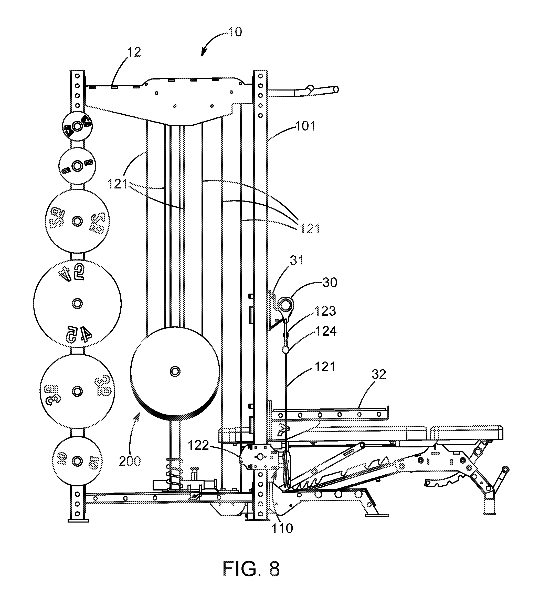
[0059] FIG. 8 is a side view the exercise machine of FIG. 6;
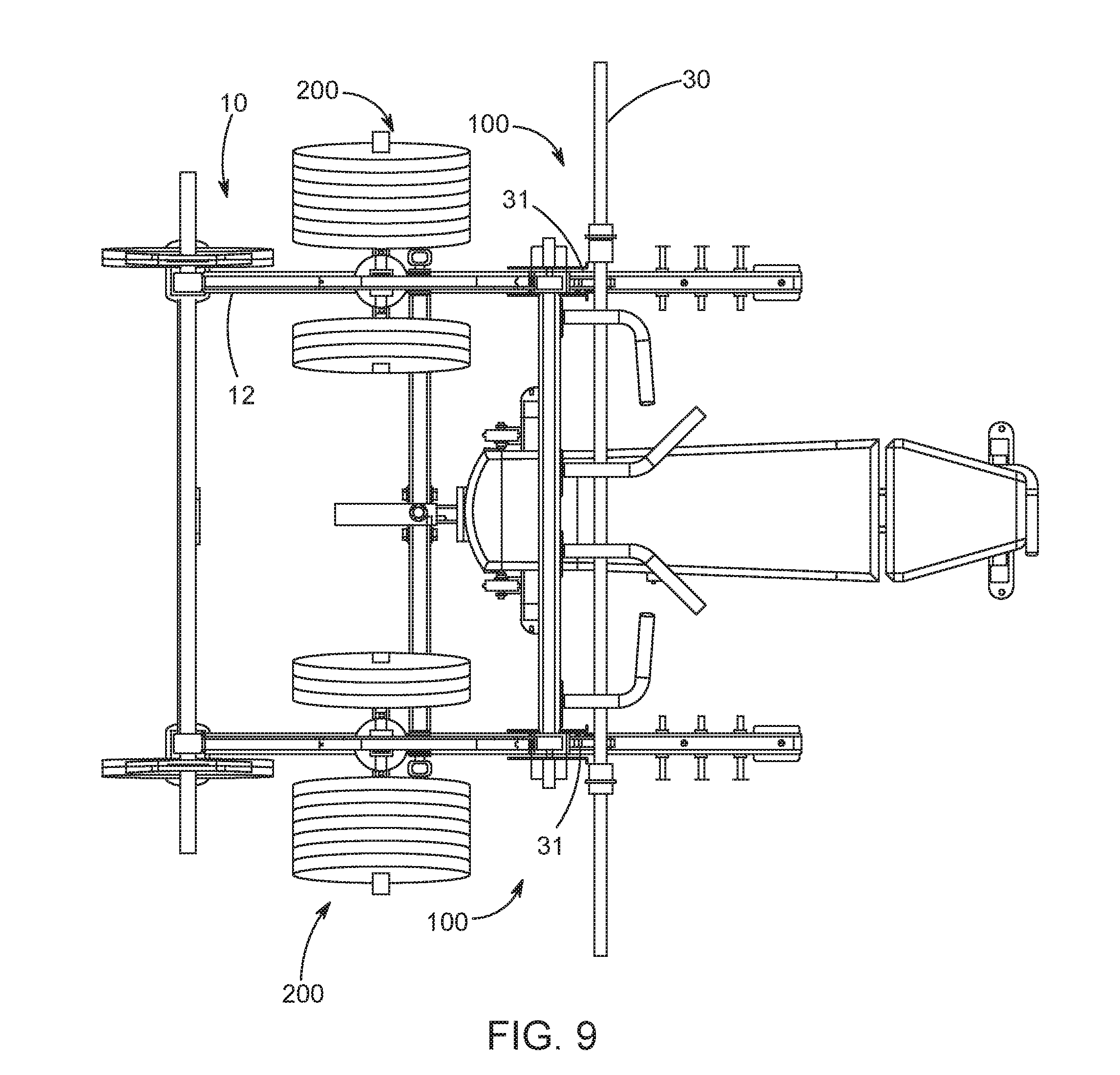
[0060] FIG. 9 is a top view the exercise machine of FIG. 6;
[0061] FIG. 10 is a side view of the exercise machine of FIG. 6 with a user performing a chest press exercise;
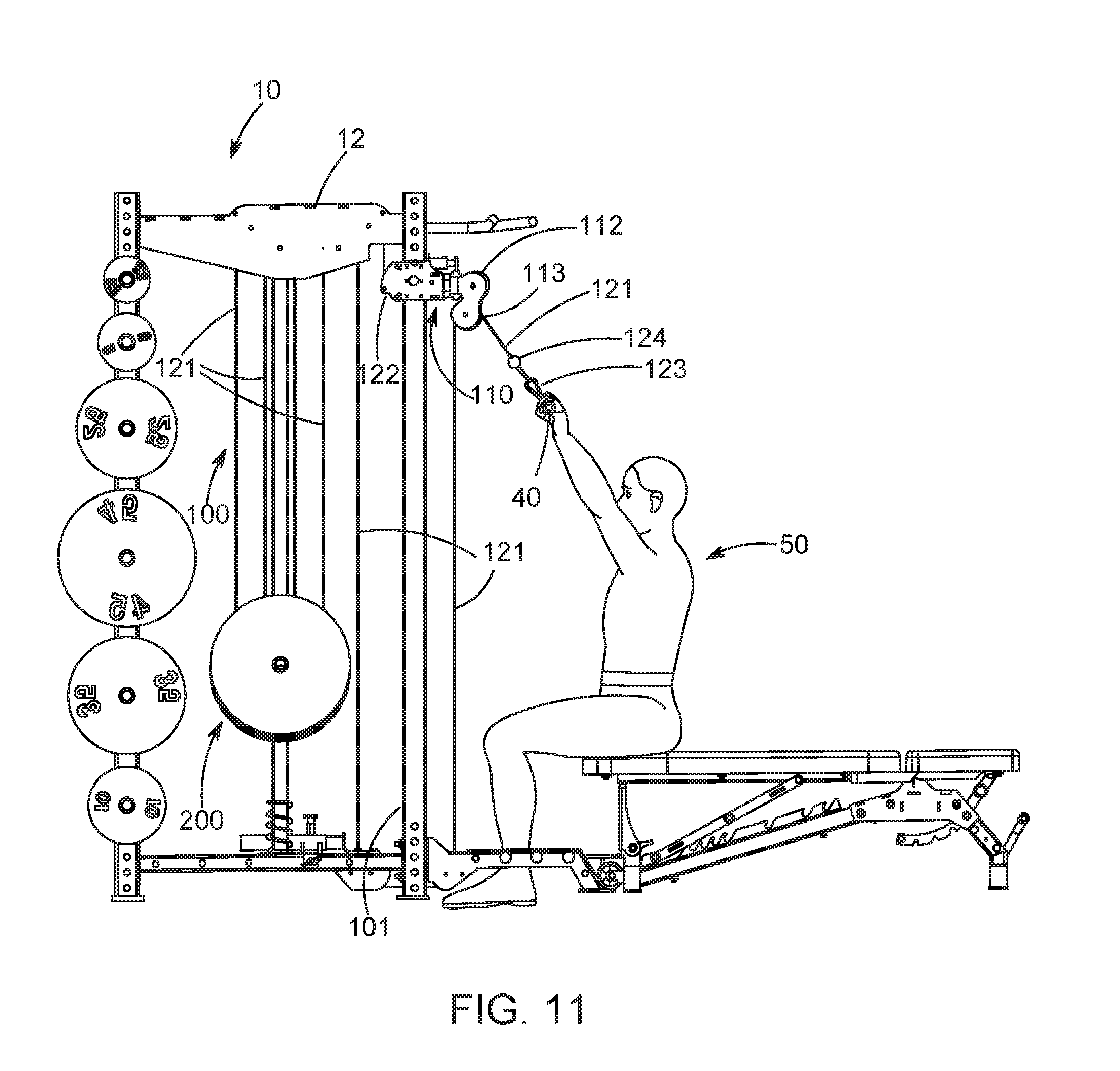
[0062] FIG. 11 is a side view of the cable exercise machine of FIG. 1 with the user performing a pulldown exercise; and
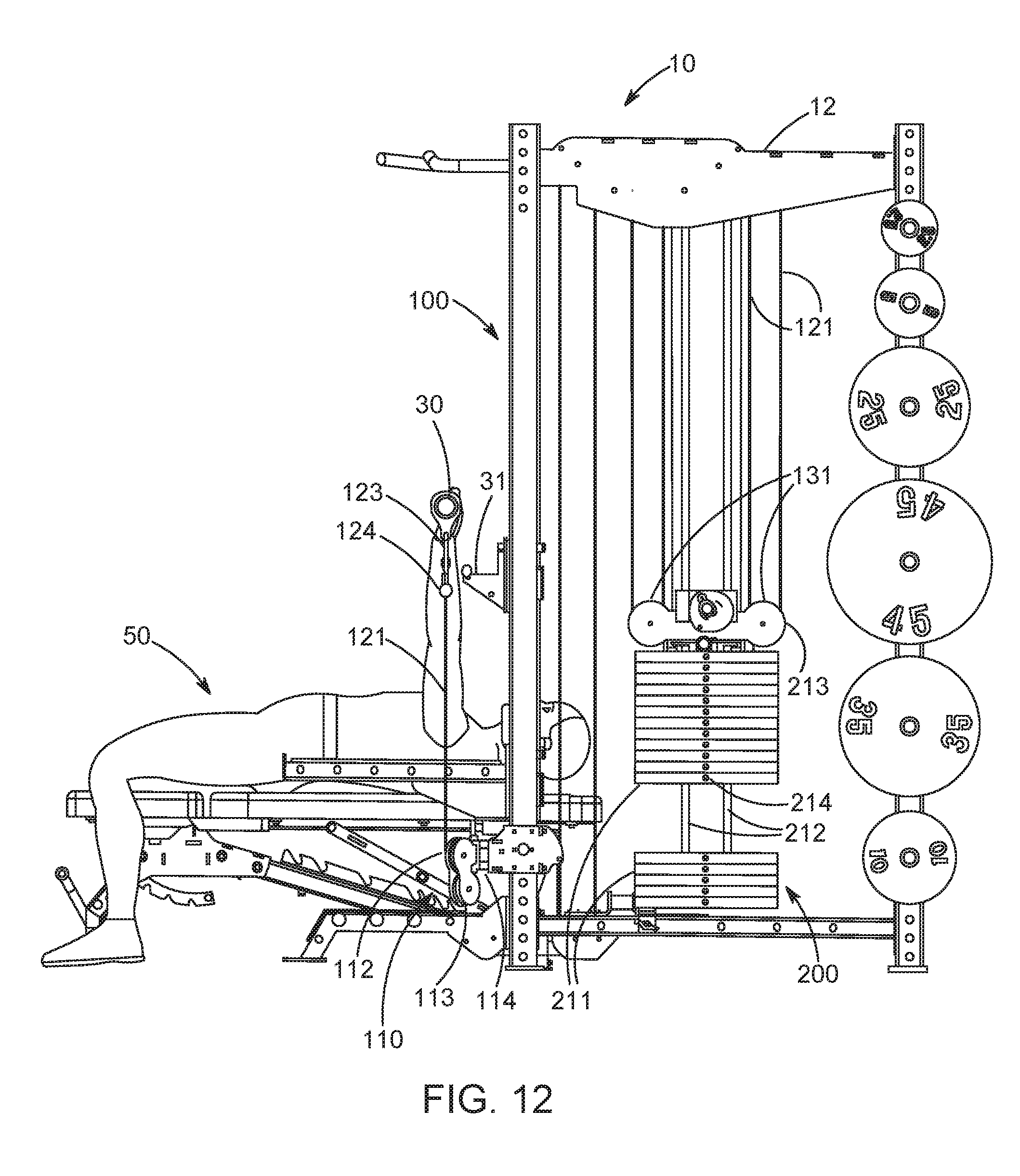
[0063] FIG. 12 is a side view of the exercise machine of FIG. 6 showing an alternative counterweight arrangement.
DESCRIPTION OF THE INVENTION
[0064] For purposes of the description hereinafter, the terms "upper", "lower", "right", "left", "vertical", "horizontal", "top", "bottom", "lateral", "longitudinal", and derivatives thereof shall relate to the disclosure as it is oriented in the figures. However, it is to be understood that the disclosure may assume alternative variations and step sequences, except where expressly specified to the contrary. It is also to be understood that the specific devices and processes illustrated in the attached drawings, and described in the following specification, are simply exemplary aspects of the disclosure. Hence, specific dimensions and other physical characteristics related to the aspects disclosed herein are not to be considered as limiting.
[0065] The present disclosure relates generally to exercise or weight machines and, more particularly, to an adjustable high-low pulley rack that allows a user to vary the location of a pull cable for performing exercises on a cable exercise or weight machine. Certain aspects of the components of the exercise or weight machine and the high-low pulley rack system are illustrated in FIGS. 1-12.
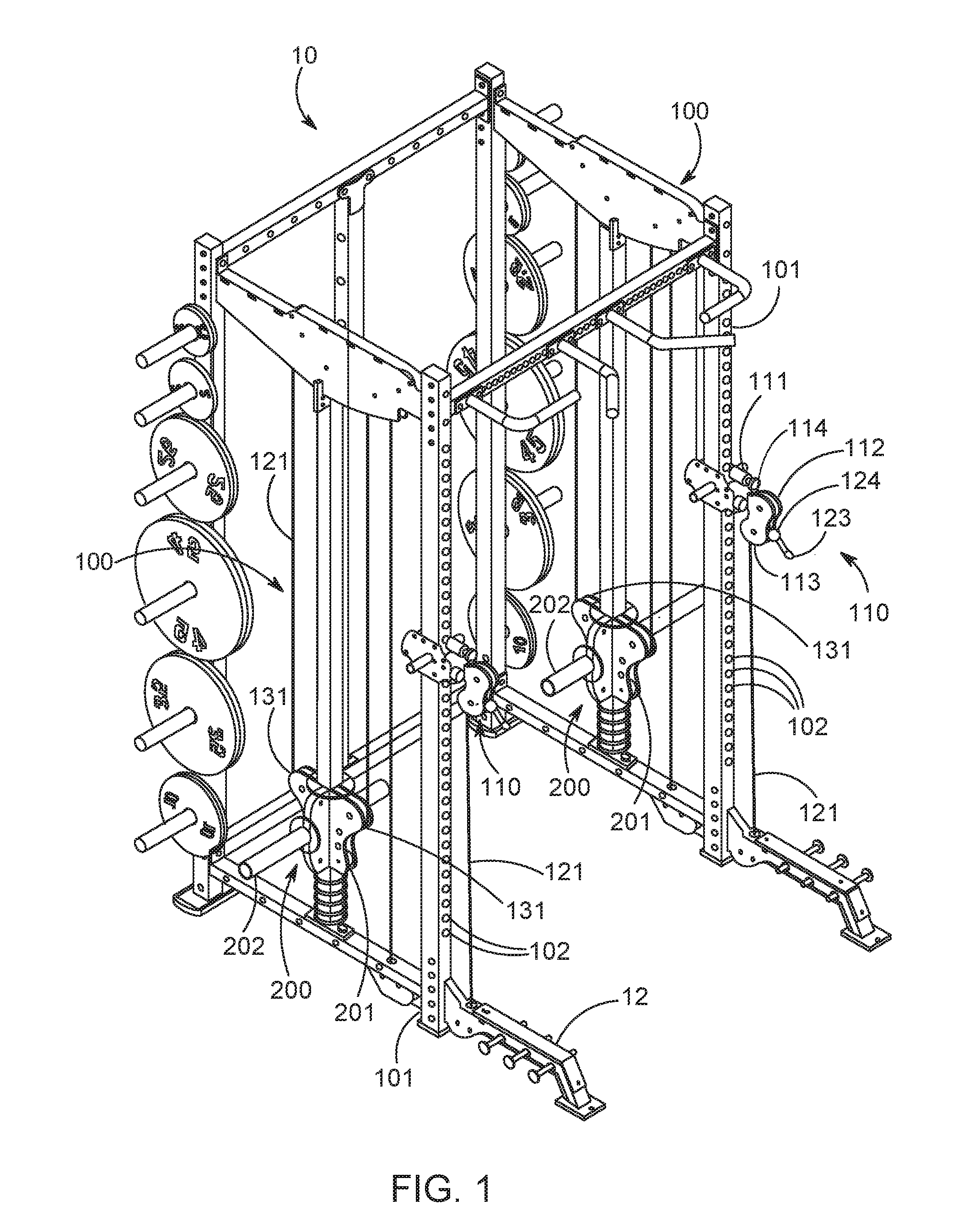
[0066] Referring now to FIGS. 1-4, an exercise machine 10 including a high-low pulley rack 100 is shown. The exercise machine 10 includes a support frame 12 to which the counterweights 200 and the components of the high-low pulley rack 100 are attached. In particular, the high-low pulley rack 100 includes uprights 101, cable end assemblies 110, and pull cables 121. The exercise machine 10 as illustrated in FIG. 1 shows a pair of high-low pulley racks 100 arranged in tandem on the exercise machine 10. However, it is to be understood that in other aspects, a single high-low pulley rack 100 may be used.
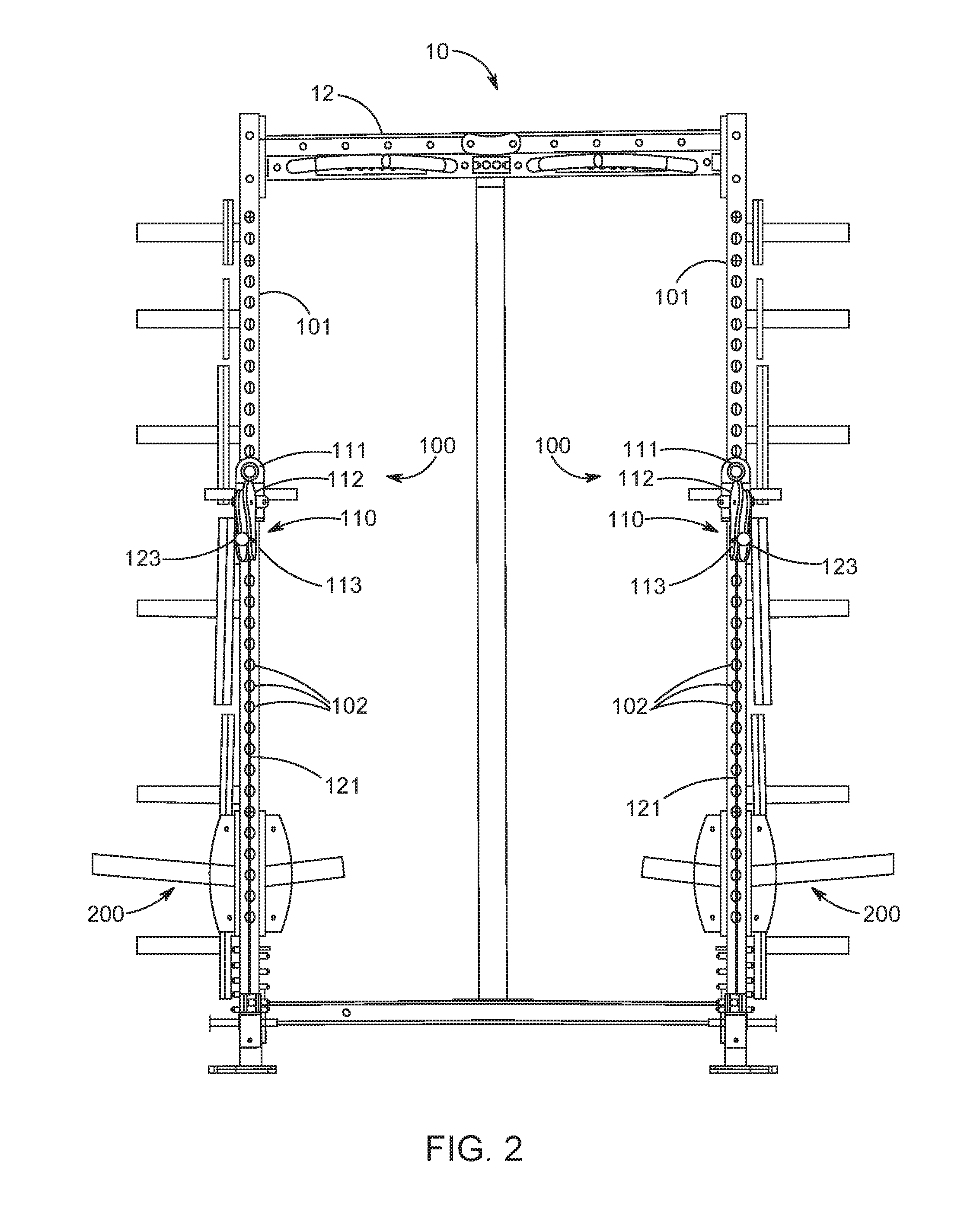
[0067] Referring now to FIG. 2, each upright 101 includes a plurality of indexing holes 102 spaced vertically along the upright 101. The plurality of index holes 102 cooperate with a popper pin 111 of the cable end assembly 110 to lock the cable end assembly 110 to the upright 101. The popper pin 111 of the cable end assembly 110 can be locked into any one of the plurality of index holes 102, permitting the user to position the cable end assembly 110 at a desired vertical position on the upright 101.
[0068] Referring now to FIG. 3, each cable end assembly 110 of the high-low pulley rack system 100 includes the popper pin 111, an upper end pulley 112, and a lower end pulley 113. The upper end pulley 112 and the lower end pulley 113 are arranged on opposing sides of the pull cable 121, such that the pull cable 121 is supported whether it is pulled downwardly or upwardly by a user. If the pull cable 121 is pulled downwardly by the user, the pull cable 121 at least partially engages the lower end pulley 113. Conversely, if the pull cable 121 is pulled upwardly, the pull cable 121 at least partially engages the upper end pulley 112. The cable end assembly 110 may include a pivot pin 114 which permits the upper end pulley 112 and the lower end pulley 113 to rotate about an axis parallel to the upright 101. In this manner, the upper end pulley 112 and the lower end pulley 113 may self-align horizontally in the direction which the pull cable 121 is pulled.
[0069] With continued reference to FIG. 3, a fixed end connection 122 of the pull cable 121 is attached to the cable end assembly 110. A pullable end 123 of the pull cable 121 freely passes through the cable end assembly 110 between the upper end pulley 112 and the lower end pulley 113. The pullable end 123 includes a retention device 124 which prevents the pullable end 123 from slipping backward through the upper end pulley 112 and the lower end pulley 113. The retention device 124 may be, for example, a ball encompassing a portion of the pull cable 121 which it too large to pass between the upper end pulley 112 and the lower end pulley 113.
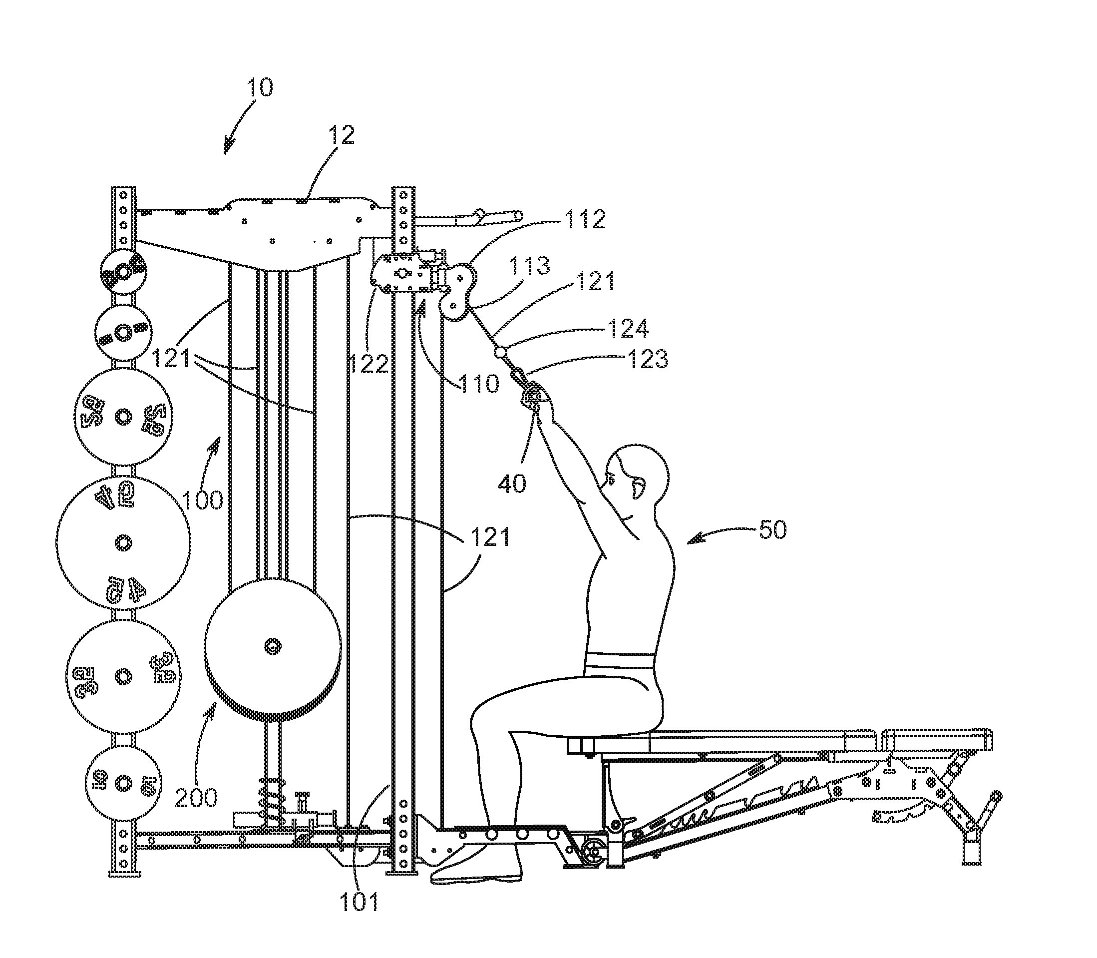
[0070] Referring now to FIG. 5, the pull cable 121 is routed from the fixed end connection 122, through the counterweight 200, and back to the pullable end 123 at the cable end assembly 110. More specifically, the pull cable 121 is routed through one or more guide pulleys 130 mounted to the support frame 12 of the exercise machine 10 and one or more counterweight pulley 131 mounted to the counterweight 200. Each of the guide pulleys 130 and counterweight pulleys 131 changes the direction of the pull cable 121. A first section 121a of the pull cable 121 extends from the fixed end connection 122 at the cable end assembly 110 to one of the counterweight pulleys 131, such that the weight of the counterweight 200 imparts tension to the pull cable 121. The first section 121a of the pull cable 121 may be routed around one or more of the guide pulleys 130 to provide additional guidance and stabilization to the first section 121a. A second section 121b of the pull cable 121 extends from one of the counterweight pulleys 131 to the pullable end 123 of the pull cable 121, such that the tension imparted on the pull cable 121 by the counterweight 200 induces the pullable end 123 of the pull cable 121 towards the cable end assembly 110. The second section 121b extends downwardly from the cable end assembly 110 such that other components of the exercise machine 10 may be mounted to the upright 101 above the cable end assembly 110 without obstructing or being obstructed by the second section 121b. The second section 121b of the pull cable 121 may be routed around one or more of the guide pulleys 130 to provide additional guidance and stabilization to the second section 121b.
[0071] With continued reference to FIG. 5, the cable routing arrangement of the pull cable 121 described above allows the cable end assembly 110 to be adjusted vertically along the upright 101 as desired by the user. When the popper pin 111 of the cable end assembly 110 is released and the cable end assembly 110 is moved up or down the upright 101, the pull cable 121 travels freely over the guide pulleys 130 and the counterweight pulleys 131 without moving the counterweight 200.
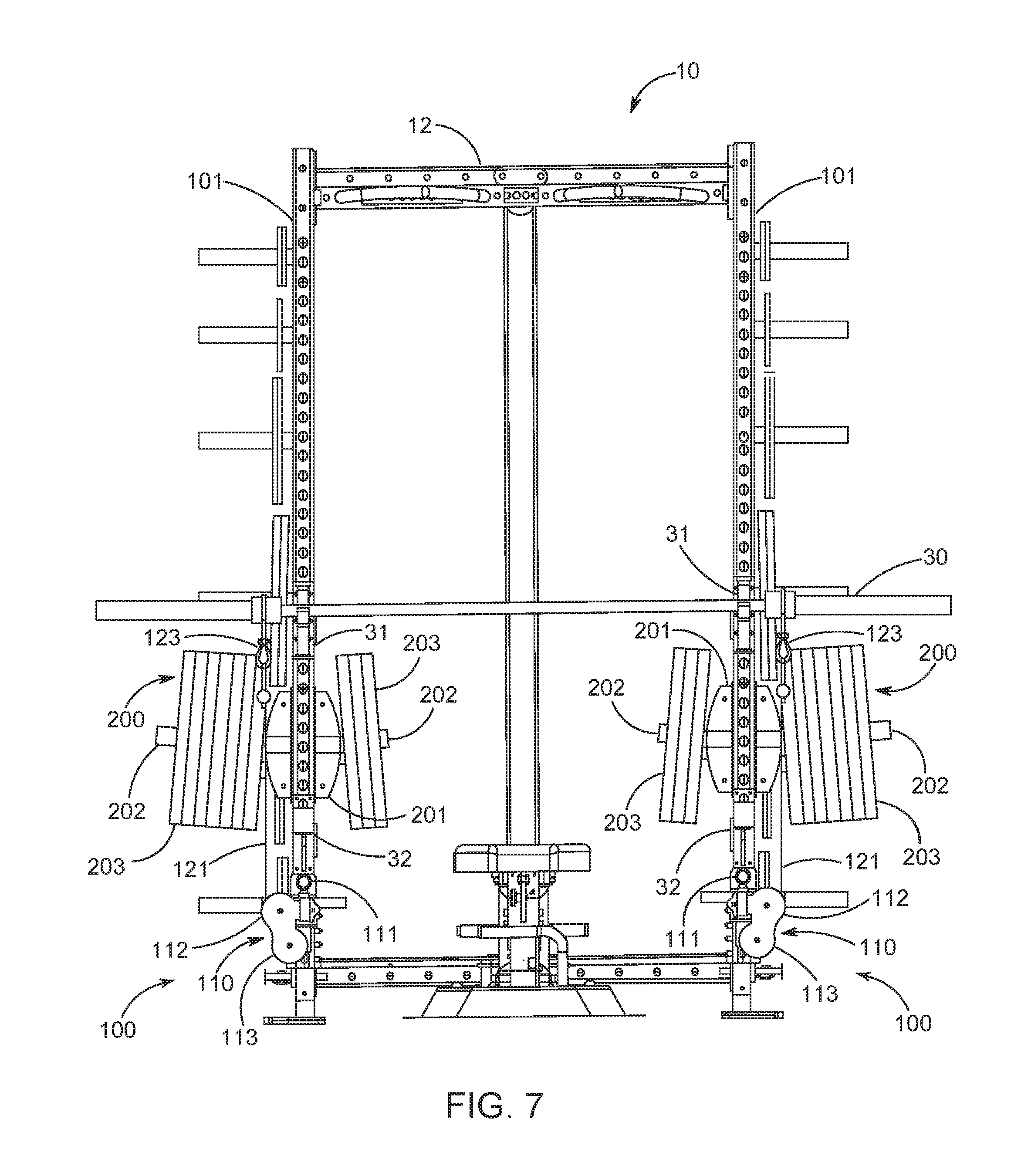
[0072] Referring now to FIG. 6-9, the exercise machine 10 is shown with the high-low pulley rack 100 is arranged for the user 50 to perform a chest press exercise. A barbell 30 is positioned on bar catches 31 mounted to the uprights 101. Additionally, safety spotter arms 32 are mounted to the uprights 101 below the bar catches 31. The cable end assemblies 110 are attached to the uprights 101 in a position below the bar catches 31 and safety spotter arms 32. The pullable ends 123 of the pull cables 121 are routed around the upper end pulley 112 of the cable end assemblies 110, and the pullable ends 123 are clipped to the barbell 30 such that pushing the barbell 30 upwards imparts tension to the pull cables 121. Referring now to FIG. 10, if sufficient force is exerted against the barbell 30 by the user 50, the force transmitted through the pull cables 121 raises the counterweight 200.
[0073] Referring now to FIG. 11, the exercise machine 10 is shown with the high-low pulley rack system 100 is arranged for the user 50 to perform a pulldown exercise. The cable end assemblies 110 are attached to the uprights 101 in a position above the user 50, and a bar or other gripping device 40 is attached to the pullable ends 123 of the pull cables 121. The pullable ends 123 are routed around the lower end pulley 113 of the cable end assemblies 110, and the user 50 exerts downward force on the pull cables 121 to raise the counterweight 200.
[0074] Various embodiments of the counterweights 200 may be used with the high-low pulley rack 100. FIGS. 1-11 illustrate a trolley arrangement for the counterweight 200. Referring back to FIGS. 1 and 7, a trolley 201 houses the counterweight pulleys 131. The trolley slides up and down a guide of the support frame 12 as the pull cable 121 is pulled by the user 50. The trolley 201 may have one or more pegs 202 projecting generally outwardly such that standard weightlifting plates 203 may be loaded onto the pegs 202.
[0075] Alternatively, the counterweights 200 may be a weight stack arrangement, as shown in FIG. 12. The weight stack arrangement includes a plurality of plates 211 having axially aligned bores which slide along one or more guide shafts 212 connected to the support frame 12. A carrier 213 houses the counterweight pulleys 131. A pin 214 or other locking mechanism may be used to fix one or more of the plurality of plates 211 to the carrier 213. Thus, when the pull cable 121 is pulled, the carrier 213 and any plates 211 fixed to the carrier 213 provide resistance to the user 50.
[0076] While various aspects of the high-low pulley rack 100 were provided in the foregoing description, those skilled in the art may make modifications and alterations to these aspects without departing from the scope and spirit of the invention. For example, it is to be understood that this disclosure contemplates that, to the extent possible, one or more features of any aspect can be combined with one or more features of any other aspect. Accordingly, the foregoing description is intended to be illustrative rather than restrictive. The invention described hereinabove is defined by the appended claims and all changes to the invention that fall within the meaning and the range of equivalency of the claims are to be embraced within their scope.
* * * * *
D00000
D00001
D00002
D00003
D00004
D00005
D00006
D00007
D00008
D00009
D00010
D00011
D00012
XML
uspto.report is an independent third-party trademark research tool that is not affiliated, endorsed, or sponsored by the United States Patent and Trademark Office (USPTO) or any other governmental organization. The information provided by uspto.report is based on publicly available data at the time of writing and is intended for informational purposes only.
While we strive to provide accurate and up-to-date information, we do not guarantee the accuracy, completeness, reliability, or suitability of the information displayed on this site. The use of this site is at your own risk. Any reliance you place on such information is therefore strictly at your own risk.
All official trademark data, including owner information, should be verified by visiting the official USPTO website at www.uspto.gov. This site is not intended to replace professional legal advice and should not be used as a substitute for consulting with a legal professional who is knowledgeable about trademark law.