Pinion Blade Drive Mechanism For A Laparoscopic Vessel Dissector
GERHARDT; THOMAS J.
U.S. patent application number 16/390091 was filed with the patent office on 2019-08-08 for pinion blade drive mechanism for a laparoscopic vessel dissector. The applicant listed for this patent is COVIDIEN LP. Invention is credited to THOMAS J. GERHARDT.
| Application Number | 20190239940 16/390091 |
| Document ID | / |
| Family ID | 44902432 |
| Filed Date | 2019-08-08 |


| United States Patent Application | 20190239940 |
| Kind Code | A1 |
| GERHARDT; THOMAS J. | August 8, 2019 |
PINION BLADE DRIVE MECHANISM FOR A LAPAROSCOPIC VESSEL DISSECTOR
Abstract
A surgical instrument comprises a handle assembly including an actuator mounted for manipulation through an actuation stroke. An elongate shaft extends distally from the handle assembly and defines a longitudinal axis. A reciprocating member extends at least partially through the elongate shaft, and is mounted for longitudinal motion through the elongate shaft in response to manipulation of the actuator through the actuation stroke. A drive mechanism includes a first rotating component coupled to the actuator about a first circumference to induce rotational motion in the first rotating component. A second rotating component is coupled to the first rotating component such that rotational motion in the first rotating component induces rotational motion in the second rotating component. The second rotating component is coupled to the reciprocating member about a second circumference such that rotational motion of the second rotating component induces longitudinal motion in the reciprocating member. The second circumference is greater than the first circumference.
| Inventors: | GERHARDT; THOMAS J.; (LITTLETON, CO) | ||||||||||
| Applicant: |
|
||||||||||
|---|---|---|---|---|---|---|---|---|---|---|---|
| Family ID: | 44902432 | ||||||||||
| Appl. No.: | 16/390091 | ||||||||||
| Filed: | April 22, 2019 |
Related U.S. Patent Documents
| Application Number | Filing Date | Patent Number | ||
|---|---|---|---|---|
| 12773644 | May 4, 2010 | 10265118 | ||
| 16390091 | ||||
| Current U.S. Class: | 1/1 |
| Current CPC Class: | A61B 18/1402 20130101; A61B 2018/1455 20130101; A61B 17/295 20130101; A61B 2018/1412 20130101; A61B 2017/2923 20130101; A61B 18/1445 20130101 |
| International Class: | A61B 18/14 20060101 A61B018/14 |
Claims
1. A surgical instrument, comprising: a handle assembly including an actuator mounted for manipulation through an actuation stroke; an elongate shaft extending distally from the handle assembly and defining a longitudinal axis; a reciprocating member extending at least partially through the elongate shaft, the reciprocating member mounted for longitudinal motion through the elongate shaft; and a drive mechanism for inducing longitudinal motion in the reciprocating member in response to manipulation of the actuator through the actuation stroke, the drive mechanism including: a first rotating component defining a first circumference, the first rotating component coupled to the actuator about the first circumference such that the manipulation of the actuator through the actuation stroke induces rotational motion in the first rotating component; and a second rotating component defining a second circumference, the second rotating component coupled to the first rotating component such that rotational motion in the first rotating component induces rotational motion in the second rotating component, the second rotating component further coupled to the reciprocating member about the second circumference such that rotational motion of the second rotating component induces longitudinal motion in the reciprocating member, wherein the second circumference is greater than the first circumference.
2. The surgical instrument according to claim 1, wherein the first rotating component includes a pinion gear defining a plurality of discrete teeth engaged with the actuator.
3. The surgical instrument according to claim 2, wherein the actuator includes a trigger mounted for pivoting through an actuation stroke to define an angle.
4. The surgical instrument according to claim 1, wherein the first rotating component is a pulley coupled to the actuator by a belt.
5. The surgical instrument according to claim 4, wherein the actuator includes a drive wheel mounted for rotational motion.
6. The surgical instrument according to claim 1, wherein the second rotating component comprises a gear having a plurality of discrete teeth engaged with a rack having a plurality of discrete teeth, the rack being mounted for longitudinal motion.
7. The surgical instrument according to claim 6, wherein each of the plurality of discrete teeth of the rack encircle a circumferential surface of the rack, and wherein the rack is mounted for rotational motion about the longitudinal axis.
8. The surgical instrument according to claim 1, further comprising an end effector extending distally from the elongate shaft, the end effector including a pair of jaw members wherein at least one jaw member is configured to move between an open position substantially spaced from the other of the pair of jaw members and a closed position wherein the jaw members are closer together.
9. The surgical instrument according to claim 8, wherein the reciprocating member is coupled to a knife adjacent a distal end of the reciprocating member, the knife being selectively extendable through a knife channel defined in the jaw members.
10. The surgical instrument according to claim 6, wherein the pair of jaw members include at least one electrode connectable to a source of electrosurgical energy.
11. An electrosurgical instrument, comprising: a handle assembly including an actuator mounted for manipulation through an actuation stroke; an elongate shaft extending distally from the handle assembly and defining a longitudinal axis; an end effector extending distally from the elongate shaft, the end effector including a pair of jaw members wherein at least one jaw member is configured to move between an open position substantially spaced from the other of the pair of jaw members and a closed position wherein the jaw members are closer together, and wherein the pair of jaw members includes at least one electrode connectable to a source of electrosurgical energy; a reciprocating member extending at least partially through the elongate shaft mounted for longitudinal motion through the elongate shaft; a knife coupled to the reciprocating member, the knife being extendable into the end effector; and a drive mechanism for inducing longitudinal motion in the reciprocating member in response to manipulation of the actuator through the actuation stroke, the drive mechanism including gear set having a first gear engaging the actuator and a second gear engaging the reciprocating member, wherein the gear set defines a gear ratio less than one.
12. The electrosurgical instrument according to claim 11, wherein the gear ratio is about 1:2.
Description
CROSS-REFERENCE TO RELATED APPLICATIONS
[0001] This application is a continuation of U.S. patent application Ser. No. 12/773,644 filed on May 4, 2010, now U.S. Pat. No. 10,265,118, the entire contents of which are incorporated herein by reference.
INTRODUCTION
[0002] The present disclosure relates to an apparatus for joining and transecting tissue. In particular, the disclosure relates to an apparatus having a drive mechanism for advancing a blade through tissue.
BACKGROUND
[0003] Instruments such as electrosurgical forceps are commonly used in open and endoscopic surgical procedures to coagulate, cauterize and seal tissue. Such forceps typically include a pair of jaws that can be controlled by a surgeon to grasp targeted tissue, such as, e.g., a blood vessel. The jaws may be approximated to apply a mechanical clamping force to the tissue, and are associated with at least one electrode to permit the delivery of electrosurgical energy to the tissue. The combination of the mechanical clamping force and the electrosurgical energy has been demonstrated to join adjacent layers of tissue captured between the jaws. When the adjacent layers of tissue include the walls of a blood vessel, sealing the tissue may result in hemostasis, which may facilitate the transection of the sealed tissue. To transect the tissue, an operator may squeeze a trigger or manipulate a similar actuator to advance a sharpened blade distally through a channel defined in the jaws. Since it is generally not necessary to release the tissue captured between the jaws before the blade is actuated, an accurate cut may be formed that extends only through tissue that has been properly sealed. A detailed discussion of the use of an electrosurgical forceps may be found in U.S. Pat. No. 7,255,697 to Dycus et al.
[0004] Certain surgical procedures may be performed more quickly and accurately with an electrosurgical forceps having relatively longer jaws than one having shorter jaws. To this end, electrosurgical forceps have become available with jaws 60 mm in length or more. Longer jaws, however, may tend to present difficulties in transecting the sealed tissue. Since longer jaws are associated with greater distances a blade must traverse to fully transect tissue captured between the jaws, a longer actuation stroke may be required by an operator. A longer stroke may prove to be awkward or cumbersome for an operator.
SUMMARY
[0005] The present disclosure describes a surgical instrument including a handle assembly having an actuator mounted for manipulation through an actuation stroke. An elongate shaft extends distally from the handle assembly and defines a longitudinal axis. A reciprocating member extends at least partially through the elongate shaft and is mounted for longitudinal motion through the elongate shaft. A drive mechanism is included for inducing longitudinal motion in the reciprocating member in response to manipulation of the actuator through the actuation stroke. The drive mechanism includes a first rotating component defining a first circumference, wherein the first rotating component is coupled to the actuator about the first circumference such that the manipulation of the actuator through the actuation stroke induces rotational motion in the first rotating component. The drive mechanism also includes a second rotating component defining a second circumference wherein the second rotating component is coupled to the first rotating component such that rotational motion in the first rotating component induces rotational motion in the second rotating component. The second rotating component is further coupled to the reciprocating member about the second circumference such that rotational motion of the second rotating component induces longitudinal motion in the reciprocating member. The second circumference is greater than the first circumference.
[0006] The first rotating component may include a pinion gear defining a plurality of discrete teeth engaged with the actuator. The actuator may include a trigger mounted for pivoting through an actuation stroke to define an angle. Alternatively, the first rotating component may include a pulley, which is coupled to the actuator by a belt, and the actuator may include a drive wheel mounted for rotational motion.
[0007] The second rotating component may include a gear having a plurality of discrete teeth engaged with a rack also having a plurality of discrete teeth and being mounted for longitudinal motion. Each of the plurality of discrete teeth of the rack may encircle a circumferential surface of the rack, and the rack may be mounted for rotational motion about the longitudinal axis.
[0008] The surgical instrument includes an end effector extending distally from the elongate shaft. The end effector may include a pair of jaw members wherein at least one jaw member is configured to move between an open position substantially spaced from the other of the pair of jaw members and a closed position wherein the jaw members are closer together. The reciprocating member may be coupled to a knife adjacent a distal end of the reciprocating member, and the knife may be selectively extendable through a knife channel defined in the jaw members. The jaw members may include at least one electrode connectable to a source of electrosurgical energy.
[0009] According to another aspect of the disclosure, an electrosurgical instrument includes a handle assembly including an actuator mounted for manipulation through an actuation stroke. An elongate shaft extends distally from the handle assembly and defines a longitudinal axis. An end effector extends distally from the elongate shaft. The end effector includes a pair of jaw members wherein at least one jaw member is configured to move between an open position substantially spaced from the other of the pair of jaw members and a closed position wherein the jaw members are closer together. The pair of jaw members includes at least one electrode connectable to a source of electrosurgical energy. A reciprocating member extends at least partially through the elongate shaft and is mounted for longitudinal motion through the elongate shaft. A knife is coupled to the reciprocating member and is extendable into the end effector. A drive mechanism for inducing longitudinal motion in the reciprocating member in response to manipulation of the actuator through the actuation stroke includes a gear set having a first gear engaging the actuator and a second gear engaging the reciprocating member. The gear set defines a gear ratio less than one. The gear ratio may be about 1:2.
BRIEF DESCRIPTION OF THE DRAWINGS
[0010] The accompanying drawings, which are incorporated in and constitute a part of this specification, illustrate embodiments of the present disclosure and, together with the detailed description of the embodiments given below, serve to explain the principles of the disclosure.
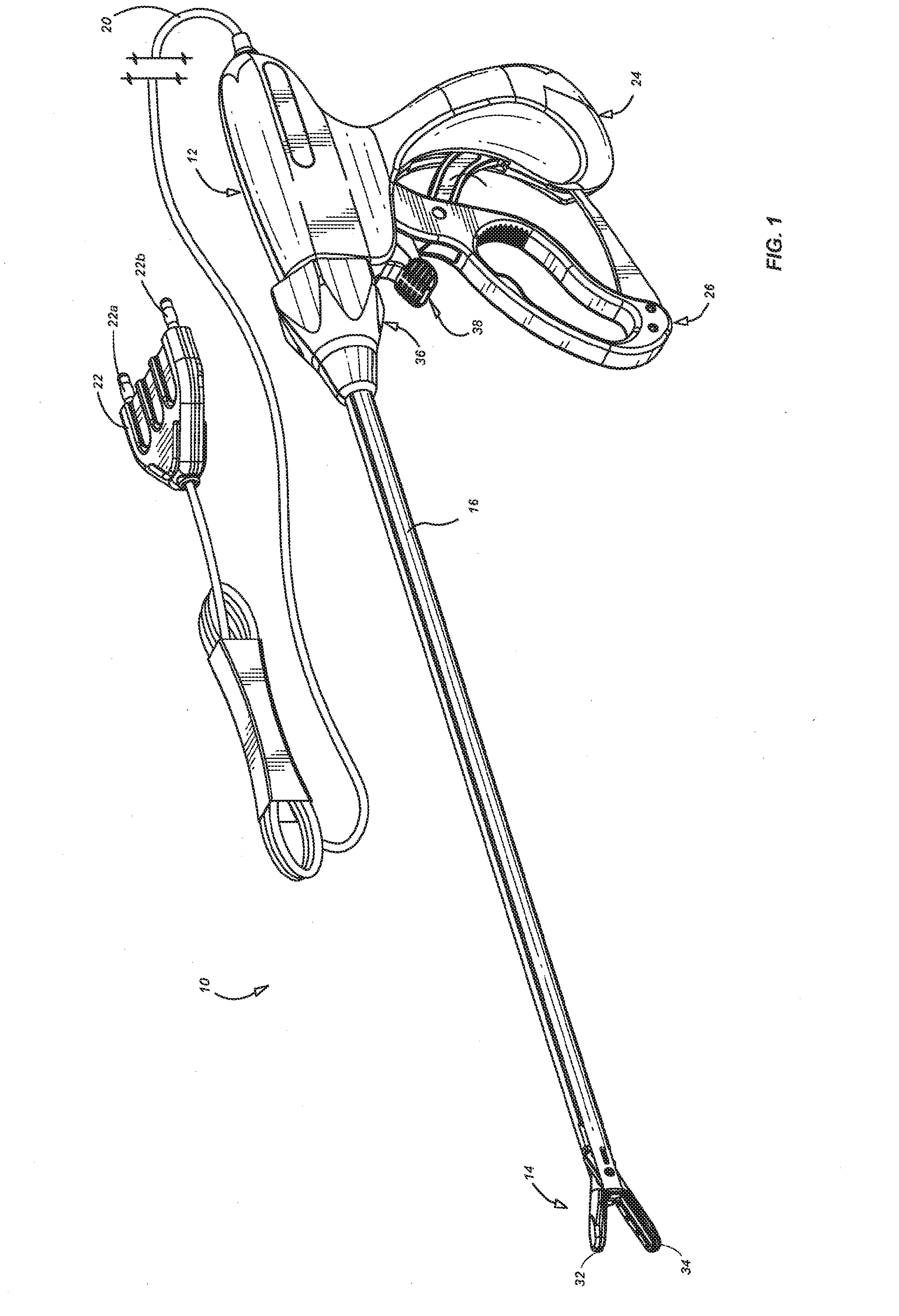
[0011] FIG. 1 is a perspective view of a surgical instrument in accordance with an embodiment of the present disclosure;
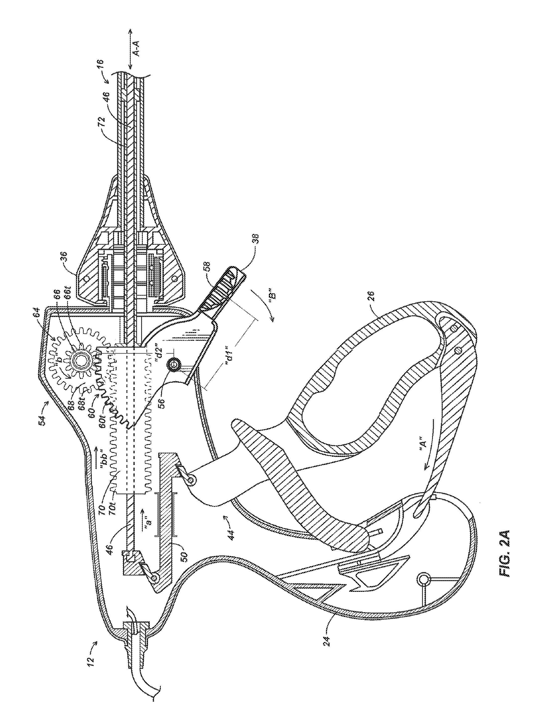
[0012] FIG. 2A is a partial, cross-sectional view of a handle assembly of the instrument of FIG. 1 depicting a trigger in an un-actuated position for maintaining a blade in a retracted position;
[0013] FIG. 2B is a partial, cross-sectional view of the handle assembly of FIG. 2A depicting the trigger in an actuated position for maintaining a blade in an advanced position;
[0014] FIG. 3A is a partial, cross-sectional view of an end effector of the instrument of FIG. 1 depicting the blade in the retracted position;
[0015] FIG. 3B is a partial, cross-sectional view of the end effector of FIG. 4 depicting the blade in the advanced position;
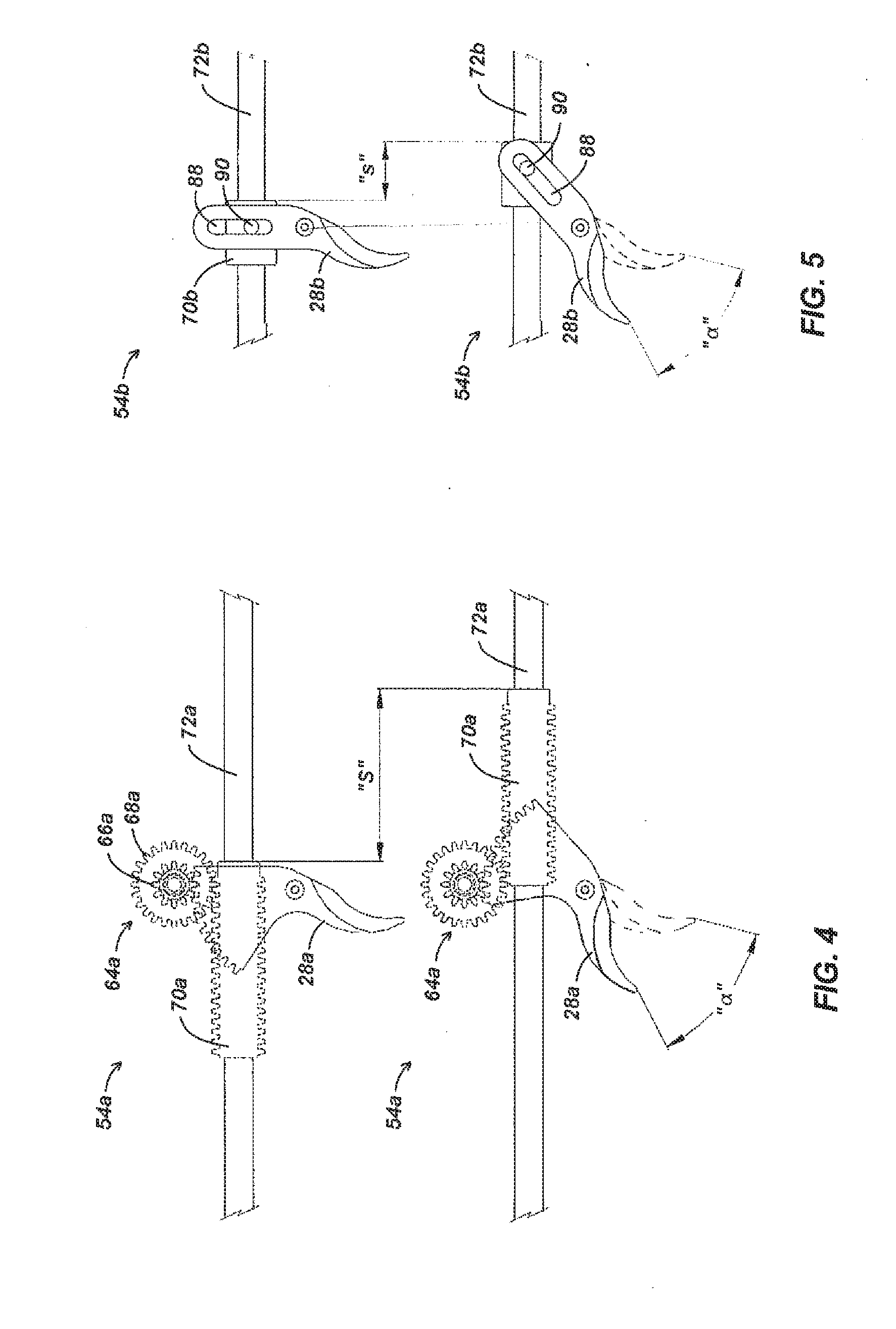
[0016] FIG. 4 is a schematic view of a pinion drive mechanism operated through an actuation stroke defining an angle;
[0017] FIG. 5 is a schematic view of a pin-and-slot drive mechanism operated through an actuation stroke defining the same angle represented in FIG. 4; and
[0018] FIG. 6 is a partial, cross-sectional view of a handle assembly depicting an alternate embodiment of a drive mechanism.
DETAILED DESCRIPTION
[0019] Referring initially to FIG. 1, an embodiment of an electrosurgical instrument is depicted generally as 10. The instrument 10 includes a handle assembly 12 for remotely controlling an end effector 14 through an elongate shaft 16. Although this configuration is typically associated with instruments for use in endoscopic surgical procedures, various aspects of the present disclosure may be practiced in connection with traditional open procedures as well.
[0020] Handle assembly 12 is coupled to an electrosurgical cable 20, which may be used to connect the instrument 10 to a source of electrosurgical energy. The cable 20 extends to connector 22 including prong members 22a and 22b that are dimensioned to mechanically and electrically connect the instrument 10 to an electrosurgical generator (not shown). Each of the two prong members 22a and 22b may be associated with an opposite electrical terminal or potential (supplied by the generator) such that bipolar energy may be conducted through the cable 20, and to the end effector 14. Alternatively, the instrument 10 may include a battery and/or a generator (not shown) disposed onboard the instrument 10 such that the instrument may operate as a self-contained unit.
[0021] To control the end effector 14, the handle assembly 12 includes a stationary handle 24 and movable handle 26. The movable handle 26 may be separated and approximated relative to the stationary handle 24 to respectively open and close the end effector 14. In FIG. 1, the end effector 14 is depicted in an open configuration wherein upper and lower jaw members 32 and 34 are separated from one another such that tissue may be received therebetween. The jaw members 32, 34 are pivotally coupled to the elongate shaft, and thus may be moved to a closed configuration (See FIG. 3A) wherein the jaw members 32, 34 are closer together for clamping the tissue. Any known mechanism may be incorporated into the instrument 10 to operatively couple the jaw members 32, 34 to the handle assembly 12 including those described in U.S. Pat. No. 7,101,371 to Dycus et al. Handle assembly 12 also includes a rotation knob 36, which may be manipulated to rotate the end effector 14 about a longitudinal axis A-A defined by the elongate shaft 16, and a trigger 38 which is operable to advance a blade or knife 40 (see FIG. 3A) through end effector 14 as discussed below with reference to FIGS. 2A through 3B.
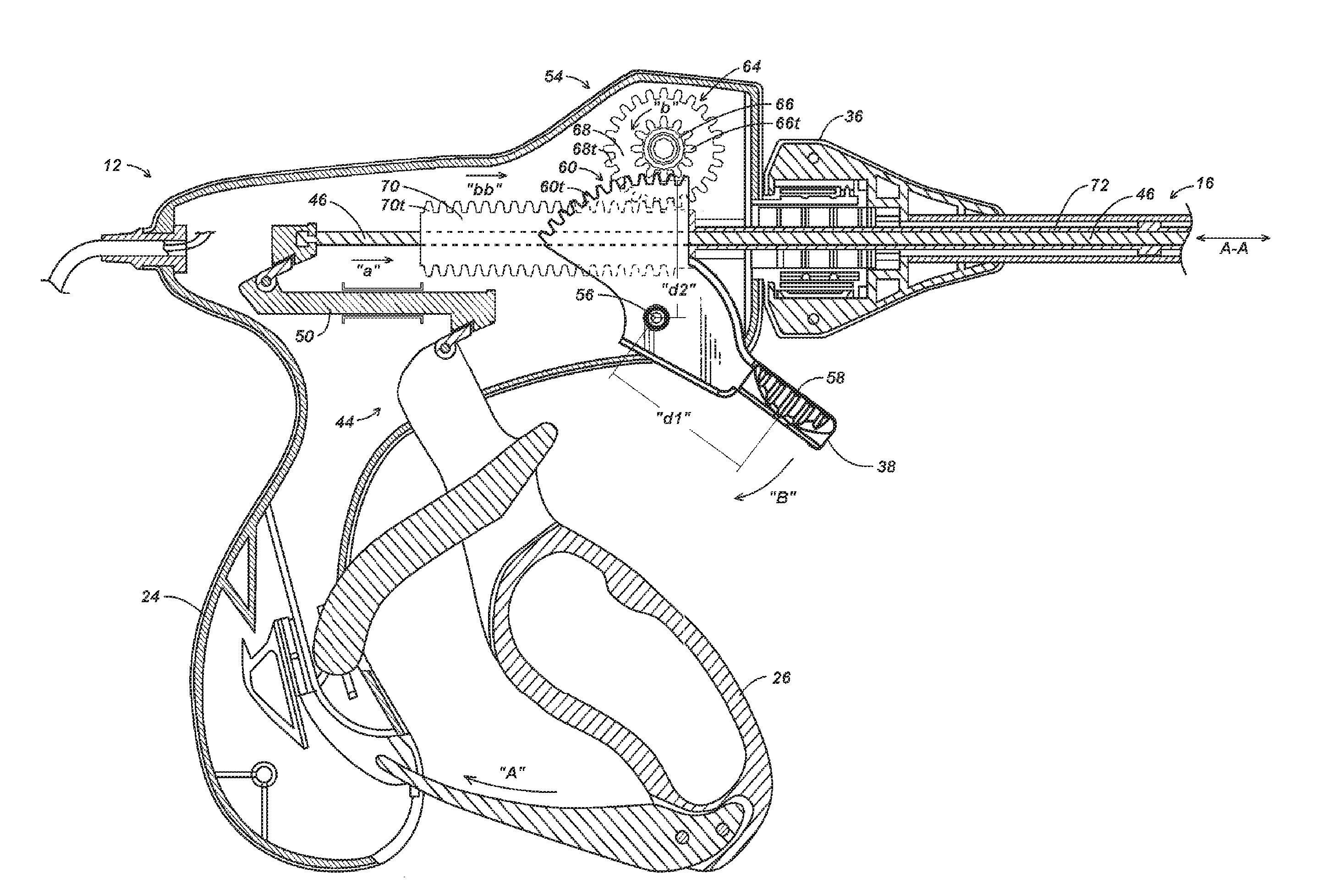
[0022] Referring now to FIG. 2A, a clamping mechanism 44 for closing the jaw members 32, 34 includes a drive rod 46 extending through the elongate shaft 16. The drive rod 46 is coupled at a proximal end to a coupling member 50, which is slidably disposed within the stationary handle 24. The coupling member 50 is operatively coupled to the movable handle 26 such that as the movable handle 26 is approximated with the stationary handle 24 in the direction of arrow "A," the coupling member 50 is driven distally in the direction of arrow "a." The drive rod 46 is, in turn, also driven in the direction of arrow "a" by the coupling member 50. Such longitudinal motion in drive rod 46 may effect pivotal motion in the jaw members 32, 34 as described below with reference to FIG. 3A.
[0023] A pinion drive mechanism 54 for advancing the knife 40 is also disposed in the handle assembly 24. The pinion drive mechanism 54 is operable by trigger 38, which is pivotally mounted to stationary handle 24 about pivot pin 56. Trigger 38 includes a grip 58 protruding to an exterior of the stationary handle 24 such that the grip 58 is accessible by an operator while gripping handle assembly 12. The grip 58 is disposed at a first distance "d1" from pivot pin 56. Opposite the grip 58, on an interior of the stationary handle 24, the trigger 38 includes a curved driving face 60. The driving face 60 is centered about pivot pin 56 at second distance "d2," and includes a plurality of discreet teeth 60t. The trigger 38 defines a simple lever mechanism such that, for a given force applied at the grip 58, a driving force delivered at the driving face 60 may be varied by varying the distances d1 and d2 from the pivot pin 56.
[0024] The teeth 60t of trigger 38 engage a circular gear set 64 that is rotatably coupled to the stationary handle 24. The gear set 64 includes a smaller pinion gear 66 and a larger intermediate gear 68. Although the ratio between the diameters of pinion gear 66 and intermediate gear 68 may vary, as depicted the smaller pinion gear 66 has a diameter approximately half the diameter of the larger intermediate gear 68, and thus exhibits a circumference about half the circumference of the intermediate gear 68. The gear set 64 defines a gear ratio of about 1:2, and thus, a tooth 68t on intermediate gear 68 travels approximately twice the distance as a tooth 66t on the pinion gear per rotation of the gear set 64. The teeth 66t of the pinion gear 66 engage the teeth 60t of the trigger driving face 60 while the teeth 68t of the intermediate gear 68 engage a cylindrical rack 70.
[0025] The cylindrical rack 70 is movably disposed about the drive rod 46, such that the rack 70 may translate longitudinally within the handle assembly 12. The rack 70 includes a plurality of circumferential teeth 70t encircling an outer surface thereof. The circumferential teeth 70t permit the rack 70 to maintain engagement with intermediate gear 68 regardless of the radial orientation of the rack 70 about the longitudinal axis A-A. Thus, the rack 70 is configured to rotate along with rotation knob 36. A distal end of the cylindrical rack 70 fixedly engages a knife tube 72 such that both rotational and longitudinal motion may be transferred between the knife tube 72 and the cylindrical rack 70. The knife tube 72 extends through the elongate shaft 16 such that the knife tube 72 may be coupled to knife 40 (FIG. 3A) as described in greater detail below.
[0026] In use, the trigger 38 may be moved from an un-actuated position, as depicted in FIG. 2A, in the direction of arrow "B", to an actuated position, as depicted in FIG. 2B to advance the knife tube 72 distally. As the trigger 38 rotates about pivot pin 56, the teeth 60t engage teeth 66t to drive the gear set 64 in the direction of arrow "b." The teeth 68t of the gear set 64, in turn, drives the cylindrical rack 70 and knife tube 72 distally in the direction of arrow "bb." The knife tube 72 may be retracted by returning the trigger 38 to the un-actuated position. The pinion drive mechanism 54 exhibits a reduction in force applied at the knife tube 72 as compared to a force applied to the trigger 38. Where greater forces are required, the trigger 72 may be modified by appropriately altering the distances "d1" and "d2."
[0027] Referring now to FIGS. 3A and 3B, the knife tube 72 is coupled to knife 40 proximate a distal end of the knife tube 72. The knife 40 is bifurcated to define a central elongate slot 74 therein. The elongate slot 74 permits longitudinal reciprocation of the drive rod 46 therethrough in response to manipulation of the movable handle 26 (FIG. 2A). The drive rod 46 is coupled to jaw members 32, 34 by a drive pin 76 extending through angled slots 78 defined in the jaw members 32, 34. The drive pin 76 reciprocates longitudinally with the drive rod 46 such that the drive pin 76 engages the angled slots 78 to cause jaw members 32, 34 to pivot about pivot pin 80, and thus moves the jaw members 32, 34 between open and closed positions.
[0028] Reciprocation of the knife tube 72 in response to manipulation of the trigger 38, induces reciprocation of the knife 40 between a retracted position as depicted in FIG. 3A, and an advanced position as depicted in FIG. 3B. The retracted position of the knife 40 corresponds to the un-actuated position of trigger 38 (FIG. 2A) and the advanced position of the knife 40 corresponds to the actuated position of the trigger (FIG. 2B). In the advanced position, a sharpened cutting edge 82 of the knife 40 extends into a knife channel 84 defined in the jaw members 32, 34. The knife channel 84 extends between laterally disposed electrodes 86 on the jaw members 32, 34, which are configured to electrosurgically seal or otherwise treat tissue. The knife 40 may thus be moved from the retracted position wherein the cutting edge 82 is proximal to the electrodes 86 to the advanced position while transecting tissue captured between the electrodes 86. The length of the jaws 32, 34 defines the knife stroke "S," or the distance the knife 40 must travel between the retracted and advanced positions, to fully transect tissues captured between the electrodes 86. The knife stroke "S," corresponds to the distance the rack 70 travels as the trigger 38 is moved between the un-actuated and actuated positions (see FIGS. 2A and 2B).
[0029] For a given actuation stroke, a pinion drive mechanism 54a as depicted in FIG. 4 may offer a greater knife stroke "S" than a pin-and-slot drive mechanism 54b as depicted in FIG. 5. The pinion drive mechanism 54a includes a trigger 28a, which is pivotable through an actuation stroke defining an angle "a". Movement of the trigger 28a through the actuation stroke rotates a gear set 64a, which in turn drives the rack 70a in a longitudinal direction as described above with reference to FIGS. 2A and 2B. The rack 70a, and thus a knife tube 72a, is translated through knife stroke "S."
[0030] The pin-and-slot mechanism 54b includes a trigger 28b, which is pivotable through an actuation stroke defining the same angle "a". The trigger 28b includes a slot 88, which engages a pin 90 of a translation block 70b. The translation block 70b is driven in a longitudinal direction as the trigger 28b pivots. Movement of the trigger 28b though the actuation stroke, however, translates the block 70b, by only a reduced knife stroke "s."
[0031] For components sized and positioned suitably for use in a surgical instrument, the knife stroke "S" and the reduced knife stroke "s" have been empirically determined for an actuation stroke defining an angle "a" of 47.97.degree.. The pinion drive mechanism 54a yielded a knife stroke "S" of 54.6 mm while the pin-and-slot drive mechanism yielded a reduced knife stroke "s" of 19.8 mm. A pinion drive mechanism 54a may achieve such a knife stroke "S" when an intermediate gear 68a exhibits a diameter approximately twice the diameter of a pinion gear 66a.
[0032] Referring now to FIG. 6, an alternate embodiment of a drive mechanism 102 is housed in a handle assembly 112. Drive mechanism 102 includes a drive wheel 114 rotatably mounted to a stationary handle 118. The drive wheel 114 protrudes to an exterior of the stationary handle 118 such that the drive wheel 114 is accessible by an operator while gripping handle assembly 112. A drive pulley 122 is mounted on the drive wheel 114 to such that the drive pulley 122 rotates along with the drive wheel 114. The drive pulley 122 engages a belt 126, which extends to a follower pulley 128. The belt 126 assumes a "figure-eight" configuration such that follower pulley 128 may rotate in an opposite direction than the drive pulley 122. A standard loop configuration is also contemplated for the belt 126 wherein the follower pulley 128 and drive pulley 122 rotate in the same direction. The follower pulley 128 is mounted on an intermediate gear 130 such that the intermediate gear 130 rotates along with the follower pulley 128. The intermediate gear 130 drives rack 70, which advances knife tube 72 as described above with reference to FIG. 2A.
[0033] In use, an operator may rotate the drive wheel 114 to induce longitudinal motion in the knife tube 72. As the operator rotates drive wheel 114, drive pulley 122 rotates one revolution for each revolution of the drive wheel 114. Drive pulley 122, in turn, drives follower pulley 128. The follower pulley 128 may define a smaller circumference than the drive pulley 122 such the follower pulley 128 rotates more than one revolution for each revolution of the drive pulley 122 and drive wheel 114. The intermediate gear 130 rotates one revolution for each revolution of the follower pulley 128. Since the intermediate gear 130 defines a larger circumference than the follower pulley 128, the intermediate gear 130 may drive the rack 70 and knife tube 72 a greater longitudinal distance than a direct connection between the rack and drive wheel 114.
[0034] Although the foregoing disclosure has been described in some detail by way of illustration and example, for purposes of clarity or understanding, it will be obvious that certain changes and modifications may be practiced within the scope of the appended claims.
* * * * *
D00000
D00001
D00002
D00003
D00004
D00005
D00006
XML
uspto.report is an independent third-party trademark research tool that is not affiliated, endorsed, or sponsored by the United States Patent and Trademark Office (USPTO) or any other governmental organization. The information provided by uspto.report is based on publicly available data at the time of writing and is intended for informational purposes only.
While we strive to provide accurate and up-to-date information, we do not guarantee the accuracy, completeness, reliability, or suitability of the information displayed on this site. The use of this site is at your own risk. Any reliance you place on such information is therefore strictly at your own risk.
All official trademark data, including owner information, should be verified by visiting the official USPTO website at www.uspto.gov. This site is not intended to replace professional legal advice and should not be used as a substitute for consulting with a legal professional who is knowledgeable about trademark law.