Ultrasonic Surgical Blades
Witt; David A. ; et al.
U.S. patent application number 16/293848 was filed with the patent office on 2019-08-08 for ultrasonic surgical blades. The applicant listed for this patent is Ethicon LLC. Invention is credited to Kevin L. Houser, Jeffrey D. Messerly, David A. Witt.
| Application Number | 20190239919 16/293848 |
| Document ID | / |
| Family ID | 40409780 |
| Filed Date | 2019-08-08 |


View All Diagrams
| United States Patent Application | 20190239919 |
| Kind Code | A1 |
| Witt; David A. ; et al. | August 8, 2019 |
ULTRASONIC SURGICAL BLADES
Abstract
An ultrasonic surgical blade includes a body having a proximal end, a distal end, and an outer surface. The distal end is movable relative to a longitudinal axis in accordance with ultrasonic vibrations applied to the proximal end. At least a portion of the outer surface of the body comprises a lubricious coating adhered thereto. The lubricious coating has a coefficient of friction that is less than the coefficient of friction of the outer surface of the body.
| Inventors: | Witt; David A.; (Maineville, OH) ; Messerly; Jeffrey D.; (Cincinnati, OH) ; Houser; Kevin L.; (Springboro, OH) | ||||||||||
| Applicant: |
|
||||||||||
|---|---|---|---|---|---|---|---|---|---|---|---|
| Family ID: | 40409780 | ||||||||||
| Appl. No.: | 16/293848 | ||||||||||
| Filed: | March 6, 2019 |
Related U.S. Patent Documents
| Application Number | Filing Date | Patent Number | ||
|---|---|---|---|---|
| 16006373 | Jun 12, 2018 | 10265094 | ||
| 16293848 | ||||
| 15477861 | Apr 3, 2017 | 10045794 | ||
| 16006373 | ||||
| 12274884 | Nov 20, 2008 | 10010339 | ||
| 15477861 | ||||
| 61004961 | Nov 30, 2007 | |||
| Current U.S. Class: | 1/1 |
| Current CPC Class: | A61L 31/10 20130101; A61B 2017/320093 20170801; A61B 17/320092 20130101; A61L 31/088 20130101; A61B 2017/00849 20130101; A61B 2017/00853 20130101; A61B 2017/320078 20170801; A61N 7/02 20130101; A61B 2017/320094 20170801; A61L 31/14 20130101; A61B 2017/0088 20130101; A61N 7/00 20130101; A61B 17/320068 20130101; A61L 2400/10 20130101; A61B 2017/320095 20170801 |
| International Class: | A61B 17/32 20060101 A61B017/32; A61L 31/14 20060101 A61L031/14; A61L 31/10 20060101 A61L031/10; A61L 31/08 20060101 A61L031/08; A61N 7/00 20060101 A61N007/00 |
Claims
1-20. (canceled)
21. An ultrasonic surgical blade, comprising: a body, comprising: a proximal end; a distal end movable relative to a curved axis extending from the proximal end in accordance with ultrasonic vibrations applied to the proximal end, wherein the body extends along the curved axis from the proximal end to the distal end; and a tissue treatment region comprising an outer surface, wherein the outer surface comprises a body coefficient of friction; and a coating adhered to at least a portion of the tissue treatment region and configured to directly contact the tissue to be treated, wherein the coating comprises a coating coefficient of friction that is less than the body coefficient of friction, and wherein the coating comprises a polymeric material.
22. The ultrasonic surgical blade of claim 21, wherein the body is asymmetric with respect to a longitudinal axis extending distally from the proximal end.
23. The ultrasonic surgical blade of claim 21, wherein the distal end is misaligned with a longitudinal axis extending distally from the proximal end.
24. The ultrasonic surgical blade of claim 21, wherein the polymeric material is selected from the following group: tetrafluoroethylene (TFE) and hexafluoropropylene (HFP) copolymers (FEP), liquid FEP, FEP/ceramic composites, liquid FEP ceramic epoxy composites, polytetrafluoroethylene (PTFE), PTFE/ceramic composites, and combinations thereof.
25. The ultrasonic surgical blade of claim 21, further comprising a surface treatment formed on at least a portion of the outer surface to enhance adhesion of the coating.
26. The ultrasonic surgical blade of claim 21, wherein the coating comprises a thickness of about 0.0001 inches to about 0.010 inches.
27. An ultrasonic surgical blade, comprising: an asymmetrical body, comprising: a proximal end; a distal end movable relative to an axis in accordance with ultrasonic vibrations applied to the proximal end; and a tissue treatment region comprising an outer surface, wherein the outer surface comprises a body coefficient of friction; and a coating adhered to at least a portion of the tissue treatment region and configured to directly contact the tissue to be treated, wherein the coating comprises a coating coefficient of friction that is less than the body coefficient of friction, and wherein the coating comprises a polymeric material.
28. The ultrasonic surgical blade of claim 27, wherein the asymmetrical body comprises a curved body.
29. The ultrasonic surgical blade of claim 28, wherein the curved body curves away from a longitudinal axis extending distally from the proximal end.
30. The ultrasonic surgical blade of claim 27, wherein the tissue treatment region is asymmetric with respect to a longitudinal axis extending distally from the proximal end.
31. The ultrasonic surgical blade of claim 27, wherein the polymeric material is selected from the following group: tetrafluoroethylene (TFE) and hexafluoropropylene (HFP) copolymers (FEP), liquid FEP, FEP/ceramic composites, liquid FEP ceramic epoxy composites, polytetrafluoroethylene (PTFE), PTFE/ceramic composites, and combinations thereof.
32. The ultrasonic surgical blade of claim 27, further comprising a surface treatment formed on at least a portion of the outer surface to enhance adhesion of the coating.
33. The ultrasonic surgical blade of claim 27, wherein the coating comprises a thickness of about 0.0001 inches to about 0.010 inches.
34. An ultrasonic surgical blade, comprising: a curved body, comprising: a proximal end; a distal end movable relative to an axis in accordance with ultrasonic vibrations applied to the proximal end; and a tissue treatment region comprising an outer surface, wherein the outer surface comprises a body coefficient of friction; and a coating adhered to at least a portion of the tissue treatment region and configured to directly contact the tissue to be treated, wherein the coating comprising a coating coefficient of friction that is less than the body coefficient of friction, and wherein the coating comprises a polymeric material.
35. The ultrasonic surgical blade of claim 34, wherein the curved body is asymmetric with respect to a longitudinal axis extending distally from the proximal end.
36. The ultrasonic surgical blade of claim 34, wherein the tissue treatment region is asymmetric with respect to a longitudinal axis extending distally from the proximal end.
37. The ultrasonic surgical blade of claim 34, wherein the distal end is misaligned with a longitudinal axis extending distally from the proximal end.
38. The ultrasonic surgical blade of claim 34, wherein the polymeric material is selected from the following group: tetrafluoroethylene (TFE) and hexafluoropropylene (HFP) copolymers (FEP), liquid FEP, FEP/ceramic composites, liquid FEP ceramic epoxy composites, polytetrafluoroethylene (PTFE), PTFE/ceramic composites, and combinations thereof.
39. The ultrasonic surgical blade of claim 34, further comprising a surface treatment formed on at least a portion of the outer surface to enhance adhesion of the coating.
40. The ultrasonic surgical blade of claim 34, wherein the coating comprises a thickness of about 0.0001 inches to about 0.010 inches.
Description
CROSS-REFERENCE TO RELATED APPLICATIONS
[0001] This application is a continuation application claiming priority under 35 U.S.C. .sctn. 120 to U.S. patent application Ser. No. 16/006,373, entitled ULTRASONIC SURGICAL BLADES, filed Jun. 12, 2018, now U.S. Patent Application Publication No. 2018/0289389, which is a continuation application claiming priority under 35 U.S.C. .sctn. 120 to U.S. patent application Ser. No. 15/477,861, entitled ULTRASONIC SURGICAL BLADES, filed Apr. 3, 2017, which issued on Aug. 14, 2018 as U.S. Pat. No. 10,045,794, which is a continuation application claiming priority under 35 U.S.C. .sctn. 120 to U.S. patent application Ser. No. 12/274,884, entitled ULTRASONIC SURGICAL BLADES, filed Nov. 20, 2008, which issued on Jul. 3, 2018 as U.S. Pat. No. 10,010,339, which claims the benefit under 35 U.S.C. .sctn. 119(e), of U.S. Provisional Patent Application Ser. No. 61/004,961, filed Nov. 30, 2007, entitled ULTRASONIC SURGICAL BLADES, the entire disclosures of which are hereby incorporated by reference herein.
BACKGROUND
[0002] The present disclosure is generally directed to ultrasonic surgical blades employed in ultrasonic instruments. At present, ultrasonic instruments are used in open as well as minimally invasive surgical procedures, including endoscopic and laparoscopic surgical procedures where an end-effector portion of the ultrasonic instrument is passed through a trocar to reach the surgical site. Due, in part, to the rising popularity of minimally invasive surgical procedures, ultrasonic instruments are increasingly being used for the safe and effective treatment of many medical conditions. The operation of instruments employing an ultrasonic transducer in this context is well known in the art and it will not be repeated herein for the sake of conciseness and brevity. Stated briefly, an ultrasonic transducer excited by an electrical generator produces mechanical vibrations at ultrasonic frequencies, which are transmitted longitudinally through a transmission component or waveguide to an end-effector. The mechanical vibrations induce longitudinal, transverse, or torsional vibratory movement to the end-effector relative to the transmission component. The vibratory movement of the end-effector generates localized heat within adjacent tissue, facilitating both cutting and coagulating of tissue at the same time. Accordingly, the ultrasonic vibrations, when transmitted to organic tissue at suitable energy levels using a suitable end-effector, may be used to cut, dissect, separate, lift, transect, elevate, coagulate or cauterize tissue, or to separate or scrape muscle tissue away from bone with or without the assistance of a clamping assembly.
[0003] It is generally accepted that ultrasonic instruments, and particularly ultrasonic instruments comprising contact ultrasonic elements, provide certain advantages over other surgical instruments. Among these advantages is that the ultrasonic mechanical vibrations can cut and coagulate tissue at the same time using relatively lower temperatures than conventional cutting and cauterizing surgical instruments. The nature of ultrasonic instruments lend themselves to multiple applications and a variety of end-effectors may be designed to perform numerous functions.
[0004] Ultrasonic instruments may be classified into single-element end-effector devices and multiple-element end-effector devices. Single-element end-effector devices include instruments such as blades, scalpels, hooks, and/or ball coagulators. Although generally, these types of end-effectors are formed of solid materials suitable for propagating ultrasonic waves, there also exist end-effectors with a hollow core to deliver a fluid stream or provide a suction channel. Multiple-element end-effectors include the single-element end-effector--blade--operatively coupled to a clamping mechanism for pressing or clamping tissue between the blade and the clamping mechanism. Multiple-element end-effectors include clamping scalpels, clamping coagulators or any combination of a clamping mechanism and a single-element end-effector. Clamping end-effectors are particularly useful when a substantial amount of pressure is necessary to effectively couple ultrasonic energy from the blade to the tissue. Clamping end-effectors apply a compressive or biasing force to the tissue to promote faster cutting and coagulation of tissue, particularly loose and unsupported tissue.
[0005] With this general background in mind, it should be noted that surgical environments where ultrasonic instruments are employed can be particularly harsh due to the mechanical vibratory forces applied to the end-effector, the resulting thermal effects, and the general caustic conditions present at the surgical site. For example, in use, the end-effector comes into contact with surgical matter, which includes coagulants, proteins, blood, tissue particles, and other constituent fluids. Over time, the surgical matter tends to desiccate and adhere to the outer (e.g., external) surface of the end-effector. This buildup of surgical matter tends to reduce the performance of the end-effector by reducing the ability of the end-effector to cut and/or coagulate tissue and increasing the impedance at the end-effector/tissue interface. To compensate for the increase in interface impedance, the generator supplies increasing amounts of power to the end-effector to continue transecting tissue until the power delivered by the generator exceeds a predetermined threshold at which time the generator shuts down or goes into "lockout." Lockout is a condition where the impedance of the end-effector is so high that the generator is unable to provide meaningful amounts of power to the tissue. Generator lockout is an undesirable result that occurs when the generator is unable to supply adequate power to the end-effector to complete a transection under the increased interface impedance condition. The completion of a transection is indicated to the user by the visual separation of the tissue from the device end-effector. When the generator goes into lockout, the surgical procedure is interrupted. Therefore, generator lockout results in increased cutting and transection times, or worse, down time during the surgical procedure.
[0006] Accordingly, there is a need for an end-effector with a suitable coating or suitable combination of a coating and a surface treatment to protect the end-effector from harsh surgical environments. In this regard, the suitable coating or suitable combination of a coating and a surface treatment prevents or minimizes buildup of surgical matter on the outer surface of the end-effector, minimizes generator lockout, minimizes power draw, improves pad wear in clamping type end-effectors, and improves the thermal characteristics of the end-effector. There is also needed a process of applying one or more suitable coatings to an outer surface of an end-effector to enable the adhesion of the one or more coatings to the outer surface of the end-effector.
SUMMARY
[0007] In one general aspect, the various embodiments are directed to an ultrasonic surgical blade. The ultrasonic surgical blade comprises a body having a proximal end, a distal end, and an outer surface. The distal end is movable relative to a longitudinal axis in accordance with ultrasonic vibrations applied to the proximal end. At least a portion of the outer surface of the body comprises a lubricious coating adhered thereto. The lubricious coating has a coefficient of friction that is less than the coefficient of friction of the outer surface of the body.
FIGURES
[0008] The novel features of the various embodiments are set forth with particularity in the appended claims. The various embodiments, however, both as to organization and methods of operation, may be best understood by reference to the following description, taken in conjunction with the accompanying drawings as follows.
[0009] FIG. 1 illustrates one embodiment of a multi-element end-effector.
[0010] FIG. 2 illustrates a cross-sectional view of an ultrasonic blade portion of the multi-element end-effector shown in FIG. 1 taken along line 2-2.
[0011] FIG. 3 illustrates one embodiment of a multi-element end-effector.
[0012] FIG. 4 illustrates a cross-sectional view of the ultrasonic blade portion of the multi-element end-effector shown in FIG. 3 taken along line 4-4.
[0013] FIG. 4A is an enlarged view of a portion of the cross-sectional portion of one embodiment of the ultrasonic blade portion of the multi-element end-effector shown in FIG. 3.
[0014] FIG. 4B is an enlarged view of a portion of the cross-sectional portion of one embodiment of the ultrasonic blade portion of the multi-element end-effector shown in FIG. 3.
[0015] FIG. 4C is an enlarged view of a portion of the cross-sectional portion of one embodiment of the ultrasonic blade portion of the multi-element end-effector shown in FIG. 3.
[0016] FIG. 5 illustrates one embodiment of a multi-element end-effector.
[0017] FIG. 6 illustrates a cross-sectional view of the ultrasonic blade portion of the multi-element end-effector shown in FIG. 5 taken along line 6-6.
[0018] FIG. 7 illustrates one embodiment of a multi-element end-effector.
[0019] FIG. 8 illustrates a cross-sectional view of the ultrasonic blade portion of the multi-element end-effector shown in FIG. 7 taken along line 8-8.
[0020] FIG. 9 illustrates one embodiment of a multi-element end-effector.
[0021] FIG. 10 illustrates a cross-sectional view of the ultrasonic blade portion of the multi-element end-effector shown in FIG. 9 taken along line 10-10.
[0022] FIG. 11 illustrates one embodiment of a multi-element end-effector.
[0023] FIG. 12 illustrates a cross-sectional view of the ultrasonic blade portion of the multi-element end-effector shown in FIG. 11 taken along line 12-12.
[0024] FIG. 13 illustrates one embodiment of a single element end-effector.
[0025] FIG. 14 illustrates a cross-sectional view of an ultrasonic blade portion of the single element end-effector shown in FIG. 13 taken along line 14-14.
[0026] FIG. 15 illustrates one embodiment of a multi-element end-effector.
[0027] FIG. 16 illustrates a cross-sectional view of an ultrasonic blade portion of the multi-element end-effector shown in FIG. 15 taken along line 16-16.
[0028] FIG. 17 illustrates one embodiment of a multi-element end-effector.
[0029] FIG. 18 illustrates a cross-sectional view of an ultrasonic blade portion of the multi-element end-effector shown in FIG. 17 taken along line 18-18.
DESCRIPTION
[0030] Before explaining the various embodiments in detail, it should be noted that the embodiments are not limited in application or use to the details of construction and arrangement of parts illustrated in the accompanying drawings and description. The surgical instruments and end-effector configurations disclosed herein are illustrative only and not meant to limit the scope of the appended claims or application thereof. The illustrative embodiments may be implemented or incorporated in other embodiments, variations and modifications, and may be practiced or carried out in various ways. Furthermore, unless otherwise indicated, the terms and expressions employed herein have been chosen for the purpose of describing the illustrative embodiments for the convenience of the reader and are not to limit the scope thereof.
[0031] The various embodiments relate, in general, to end-effectors for use in ultrasonic surgical instruments. An ultrasonic surgical instrument generally comprises an ultrasonic transducer, an ultrasonically activated end-effector, and a substantially solid, or hollow, ultrasonic waveguide that connects the ultrasonic transducer to the end-effector. The ultrasonic transducer is contained in a transducing handpiece. The end-effector may be formed of a base material (e.g., body) that is suitable for efficiently transmitting or propagating acoustic waves at ultrasonic frequencies. Thus, the end-effector is an ultrasound-propagating element, which may be coupled to the ultrasonic transducer either directly or by way of the ultrasonic transmission waveguide. Examples of ultrasonic surgical instruments are disclosed in U.S. Pat. Nos. 5,322,055 and 5,954,736 and combinations of ultrasonic end-effectors (e.g., blades) and surgical instruments are disclosed in U.S. Pat. Nos. 6,309,400 B2, 6,278,218 B1, 6,283,981 B1, and 6,325,811 B1, which are incorporated herein by reference in their entirety. These references provide a suitable general description of ultrasonic instruments and end-effectors. Accordingly, the particular operation of such ultrasonic instruments and end-effectors will not be discussed in detail herein.
[0032] More particularly, the embodiments are directed to ultrasonic end-effectors comprising one or more coatings formed as layers of materials, surface treatments, and/or any combination thereof. A suitable coating formed on an outer surface of an ultrasonic end-effector provides a lubricating effect and, therefore, is useful in minimizing adhesion of surgical matter to the outer surface of the end-effector. The lubricating coating also reduces friction between the end-effector and the tissue and thus minimizes the interface impedance between the end-effector and the tissue and reduced the heat buildup in the end-effector. This results in less power being drawn from the ultrasonic generator and an end-effector with a cooler thermal profile that minimizes generator lockout and improves the overall operational stability of the surgical instrument. One skilled in the art would expect that a decrease in average power draw (due, again, to reduced interface impedance) would result in a corresponding increase in the time required to perform surgical procedures such as the cutting and coagulation of a tissue bundle. However, this tradeoff in transection time has not been seen in testing and, in fact, an unexpected decrease in transection times has been consistently obtained. Further investigation has revealed two causes for the unexpected results that heretofore have not been described in the art: (1) the lower coefficient of friction coatings (most coatings presented herein have low friction constituents such as polytetrafluoroethylene generally known as TEFLON.RTM. and referred to hereinbelow as PTFE) do not adhere to tissue and thus the tissue releases from the blade (the indication of a completed transection) more uniformly and more quickly than a comparable uncoated blade and (2) the lower coefficient of friction and, therefore, interface impedance, results in a lower average power draw and therefore far fewer incidents of generator lockout. In some embodiments, the transection time has been reduced by about 34% by virtue of the first listed cause. In some embodiments, lengths of thick, tough tissue (uterine broad ligament, for example) have been transected in successive applications with a coated end-effector blade while a comparable uncoated instrument was unable (in any reasonable length of time) to accomplish the same task; this due to the second listed cause. In use, various embodiments of the end-effector blades comprising one or more coatings as described herein, may improve tissue effects such as hemostasis by providing more uniform transection and/or coagulation of tissue.
[0033] As described herein, a coating may comprise one or more layers of materials formed on an outer surface of a body portion of an ultrasonic end-effector. The outer surface of the end-effector may be partially or completely coated with one or more than one layer of material. Each layer may comprise one or more materials. In other embodiments, one or more surface treatments may be applied either to the entire end-effector body or to a portion thereof. Still in other embodiments, the end-effector body may comprise a combination of coatings and applications of surface treatments. This combination may be applied to the entire end-effector or to a portion thereof.
[0034] In some embodiments, materials, surface treatments, and/or combinations thereof, may be suitably applied to an outer surface of the end-effector, or portion thereof, to produce an end-effector having a coefficient of friction that is lower than that of the end-effector base material alone. End-effectors with a lower coefficient of friction operate at lower temperatures and minimize generator lockout promoting faster cutting of tissue. In other embodiments, surface treatments may be suitably applied to an outer surface of the end-effector, or portion thereof, to produce an end-effector having a coefficient of friction that is greater than that of the end-effector base material alone. End effectors with a higher coefficient of friction improve the tissue sealing effects of the end-effector. Therefore, in some embodiments, it may be desirable to provide an end-effector with a lower coefficient of friction in the cutting region and a higher coefficient of friction in the tissue sealing region by applying various combinations of coatings and surface treatments to different portions of the end-effector.
[0035] Certain embodiments will now be described to provide an overall understanding of the principles of the structure, function, manufacture, and use of the devices and methods disclosed herein. One or more examples of these embodiments are illustrated in the accompanying drawings. Those of ordinary skill in the art will understand that the devices and methods specifically described herein and illustrated in the accompanying drawings are non-limiting embodiments and the scope of the various embodiments is defined solely by the claims. The features illustrated or described in connection with one embodiment may be combined with the features of other embodiments. Such modifications and variations are intended to be included within the scope of the appended claims.
[0036] It will be appreciated that the terms "proximal" and "distal" are used herein with reference to a clinician gripping a hand piece assembly of an ultrasonic surgical instrument. Thus, the end-effector is distal with respect to the more proximal hand piece assembly. It will be further appreciated that, for convenience and clarity, spatial terms such as "top" and "bottom" also are used herein with respect to the clinician gripping the hand piece assembly. However, surgical instruments are used in many orientations and positions, and these terms are not intended to be limiting and absolute.
[0037] FIG. 1 illustrates one embodiment of a multi-element end-effector 100. In the illustrated embodiment, the multi-element end-effector 100 comprises a clamp arm assembly 102, shown in an open position, operatively coupled to an ultrasonic surgical blade 112 (blade). The multiple-element end-effector 100 may be employed in a conventional clamping coagulating type ultrasonic instrument, for example. The clamp arm assembly 102 comprises a clamp arm 104 and a tissue pad 106 attached to the clamp arm 104. The blade 112 is an ultrasound-propagating element suitable for coupling to conventional ultrasonic surgical instruments. The blade 112 comprises a body 108 having a proximal end and a distal end and defining an elongated treatment region therebetween. The body 108 defines a longitudinal axis A extending between the proximal end and the distal end. The proximal end is adapted and configured to couple to an ultrasonic transducer either directly or through an ultrasonic transmission waveguide in a known manner. Mechanical vibrations produced by the ultrasonic transducer propagate along the transmission waveguide and are coupled to the proximal end of the body 108. The distal end of the body 108 is selected such that it is movable relative to the longitudinal axis A by the mechanical vibrations produced by the ultrasonic transducer. The distal end and the elongated treatment region is used to effect tissue (e.g., dissect, transect, cut, coagulate). These tissue effects may be enhanced by clamping the tissue between the camp arm 104 and the blade 112.
[0038] In one embodiment, a coating 116 may be formed or applied on at least a portion of an outer (e.g., external) surface of the body 108 that at least corresponds with the elongated treatment region. The coating 116 may comprise one or more than one layer 110 formed on the outer surface of the body 108. Each of the one or more than one layer 110 may consist of one or more than one material. Accordingly, in one embodiment, the layer 110 may in effect comprise several sub-layers. In one embodiment, the coating 116 may consist of a base layer (e.g., primer layer, first layer) as well as an overcoat layer (e.g., top layer, second layer) and one or more than one layer 110 therebetween. The surface area of the body 108 may include a surface treatment applied thereto to enhance the adhesion of the layer 110 of material to the body 108. The coated blade 112 enhances tissue effects during dissecting, transecting, cutting, and coagulating and improves the operational stability of the ultrasonic surgical instrument by minimizing or eliminating generator lockout.
[0039] FIG. 2 illustrates a cross-sectional view of the ultrasonic surgical blade 112 portion of the multi-element end-effector 100 taken along line 2-2 in FIG. 1. As shown in the cross-sectional view of FIG. 2 of the illustrated embodiment, the body 108 has a substantially circular cross sectional shape. In other embodiments, the body 108 may have any suitable cross sectional shape and may be symmetric or asymmetric in nature. For example, the body 108 may have a cross-sectional shape that defines a triangle, square, rectangle, pentagon, hexagon, any suitable polygon, or irregular shape, whether symmetric or asymmetric. The body 108 may be fabricated from a base material suitable for transmission of ultrasonic energy in the form of acoustic waves. The base material of the body 108 may comprise titanium (e.g., Ti6Al-4V ELI), aluminum, stainless steel, or any material or composition that is suitable for propagating acoustic waves efficiently, for example.
[0040] In one embodiment, the coating 116 may be formed as one layer 110 over at least a portion of the outer surface of the blade body 108. The layer 110 may consist of at least one material and in other embodiments may include multiple layers consisting of a base material (e.g., primer layer, first layer) and an overcoat material (e.g., top layer, second layer) as described in more detail herein with reference to FIGS. 3 and 4. The thickness of the layer 110 may be anywhere from about 0.0001 to about 0.010 inches (0.1 mils to 10 mils). The coating 116 may partially or completely cover the outer surface of the body 108. The layer 110 may be formed over the entire body 108 or may be formed over portions of the body 108. The coating 116 material may be selected to have a lower coefficient of friction than the body 108 material.
[0041] The layer 110 may comprise a variety of materials including polymeric and polymer containing materials. The term "polymeric materials" and the word polymer, as used herein, include, but are not limited to, homopolymers, copolymers, terpolymers, and the like. Non-limiting examples of polymeric and polymer-containing materials include tetrafluoroethylene (TFE) and hexafluoropropylene (HFP) copolymers (FEP), liquid FEP, FEP/ceramic composites, liquid FEP ceramic epoxy composites, polytetrafluoroethylene (PTFE or TEFLON.RTM.), and PTFE/ceramic composites. In other non-limiting embodiments, the layer 110 may comprise a dry film lubricant, such as, but not limited to, tungsten disulfide, molybdenum disulfide, graphite, and fluorinated polymers. Still in other non-limiting embodiments, the layer 110 may comprise ceramics, such as, but not limited to, metal oxydes, metal nitrides, and metal carbides. Examples of ceramics, include, but are not limited to, chromium carbide, tungsten carbide, titanium nitride, alumina, and chromium nitride. Yet in other non-limiting embodiments, the layer 110 may comprise metals. Metals include, but are not limited to, aluminum, stainless steel, and molybdenum. In other non-limiting embodiments, the layer 110 may comprise a metallized ceramic, such as, but not limited to, stainless steel embedded in ceramic.
[0042] In various embodiments, the coating 116 may be formed in multiple layers including any of the materials previously discussed with respect to the layer 110. Examples of multi-layer coatings or composites include, but are not limited to, molybdenum/alumina/tungsten carbide, aluminum oxide/stainless steel, aluminum oxide/stainless steel 15/15%, chromium carbide/tungsten oxide, molybdenum/aluminum oxide/tungsten carbide, cobalt/molybdenum, graphite/tungsten oxide, aluminum oxide/stainless steel 25/30%, molybdenum/aluminum oxide/tungsten carbide/stainless steel, or chromium carbide/tungsten oxide, among other suitable materials.
[0043] In use, the blade 112 may be exposed to particularly harsh environments including ultrasonic vibrations, heat, and caustic solutions of blood and proteins referenced to herein as surgical matter. Consequently, the harsh operating environment tends to delaminate, erode, or wear the coating 116. Accordingly, the layer 110 should be applied to the body 108 using any suitable application technique that promotes good adhesion between the base material of the body 108 and the layer 110 to prevent or minimize delamination, erosion, or wear of the layer 110 from the body 108. The layer 110 may be applied to the body using suitable material application techniques: coating, dipping, spraying, brushing, drying, melting, laser curing, anodizing, electroplating, electroless chemical deposition, sintering, fused curing, physical vapor deposition (PVC), chemical vapor deposition (CVD), thermal spray, thick film high velocity oxygen fuel (HVOF) plasma, and any other suitable material application techniques. Other well known material deposition techniques are described in U.S. Pat. No. 7,041,088 and U.S. Pat. No. 6,663,941, which are incorporated herein by reference. One suitable material application technique is a process developed by Integrated Surgical Sciences, Corp. (ISSC) of Sedalia, Colo., USA. Alternatively, the materials for forming the coating 116, or any constituent material forming the various layers thereof, may be purchased from ISSC and applied in accordance with any suitable material application techniques.
[0044] In various embodiments, a surface treatment or a plurality of surface treatments may be applied to the body 108 using a variety of techniques: peening, sand blasting, micro blasting, bead blasting, knurling, engraving, chemical treatment such as acid or base etching, laser etching, plasma etching, corona discharge etching, heat etching, carving, scoring, vibratory deburring, abrasive flow machining, and other techniques. The surface treatment can advantageously improve the adhesion of the layer 110 to the surface of the body 108. However, care should be taken when applying surface treatments to prevent damage to the body 108 during application, which later may lead to failure of the blade 112 during use. For example, surface bead blasting may increase the stress concentrations in the end-effector body 108 and may lead to the failure of the end-effector during use. FIG. 4A illustrates one example of a surface treatment 108A that may be applied to the surface of the body 108 to enhance the adhesion of the layer 110 to the surface of the body 108.
[0045] In use, the blade 112 comprising the coating 116 formed over the body 108 provides several advantages such as improved cutting and coagulating functions over an uncoated blade. In one embodiment, the coating 116 has a coefficient of friction that is lower than the coefficient of friction of the surface of the base material of the body 108 alone. Thus, the coating 116 forms a lubricious layer over at least a portion of the body 108. The blade 112 comprising the lubricious coating 116 provides several benefits and/or advantages over conventional uncoated bare end-effector blades. For example, the coated blade 112 provides improved tissue cutting (e.g., transecting) along the longitudinal length of the blade 112 resulting in more uniform transection of tissue, improved vessel sealing and homogeneity of the tissue layer, and improved thermal and structural properties of the blade 112, which facilitates more uniform transection of the tissue. The coated blade 112 may further facilitate uniform serosa-to-serosa adhesion along the cut length of the tissue, thus minimizing or eliminating discontinuities of adhesion along the tissue cut length, which commonly occur with conventional uncoated blades. The lubricious property of the coating 116 also minimizes the adhesion of surgical matter to the surface of the blade 112 during surgical procedures. As previously discussed, "surgical matter" includes coagulants, proteins, blood, tissue, and/or other constituent fluids, which may be present during a surgical procedure and tend to desiccate and adhere to the surface of uncoated blades raising the interface impedance of the blade. As previously discussed, to compensate for the increased impedance, the ultrasonic generator supplies increasing amounts of power to the blade to continue transecting tissue until the power delivered by the generator exceeds a predetermined threshold at which time the generator shuts down or goes into "lockout." As previously discussed, lockout is a condition where the impedance of the end-effector is so high that the generator is unable to provide meaningful amounts of the power to the tissue. Therefore, by minimizing the deposition, buildup, or adhesion of surgical matter, the coated blade 112 reduces the electrical power required to operate the blade 112 when transecting tissue. As a result, the coated blade 112 minimizes the power supplied by the generator and minimizes or prevents lockouts of the generator.
[0046] Those skilled in the art will appreciate that ultrasonic end-effector blades are relatively efficient and that the electrical power required for driving the end-effector blade correlates well with the power delivered to tissue loads. Essentially, the lubricious coating 116 reduces the friction between the blade 112 and the tissue, thus reducing the thermal profile of the blade 112. Because the tissue does not adhere to the coating 116, it releases from the blade 112 more easily and uniformly than an uncoated blade requiring less average power draw (less total energy applied) and less time (even less total energy applied) than an uncoated blade giving a truly unexpected and synergistic effect. In certain instances, the time required to transect tissue, for example, may be reduced by as much as 34%. Additionally, because the coated blade 112 reduces or minimizes the number of generator lockouts that may occur over a surgical procedure, the coated blade 112 even more substantially reduces the overall time required to complete the surgical procedure.
[0047] It is generally well known that tissue pads tend to degrade and wear over time due to frictional engagement with a blade when no tissue is present therebetween. The lubricious coating 116, however, also lowers the coefficient of friction between the coated blade 112 and the tissue pad 106 and as a result can extend the life of the tissue pad 106. Accordingly, the coated blade 112 can reduce or minimize the degradation and deterioration of the tissue pad 106 caused by abrasion and frictional engagement with the blade 112. Consequently, the coated blade 112 can substantially extend the operational life of the tissue pad 106 when compared to conventional uncoated blades.
[0048] FIG. 3 illustrates one embodiment of a multi-element end-effector 200. In the illustrated embodiment, the multi-element end-effector 200 comprises a clamp arm assembly 202, shown in an open position, operatively coupled to an ultrasonic surgical blade 212 (blade). The multiple-element end-effector 200 may be employed in clamping coagulating type ultrasonic instruments, for example. The clamp arm assembly 202 comprises a clamp arm 104 and a tissue pad 106 attached thereto. The blade 212 is an ultrasound-propagating element suitable for use in ultrasonic surgical instruments. The body 108, previously discussed with reference to FIGS. 1 and 2, forms a portion of the blade 212. As previously discussed, the body 108 comprises a proximal end and a distal end and defines an elongated treatment region therebetween. The proximal end is adapted and configured to couple to an ultrasonic transducer either directly or through an ultrasonic transmission waveguide. The distal end and the treatment region is used to effect tissue (e.g., dissect, transect, cut, coagulate). In one embodiment, a coating 216 is formed on at least a portion of the outer surface of the body 108 that at least corresponds with the elongated treatment region. The coating 216 may comprise at least two layers 210, 214 of materials. In the illustrated embodiment, a primer layer 214 (e.g., base layer, first layer) may be formed on the outer surface of the body 108. An overcoat layer 210 (e.g., top layer, second layer) may be formed over the primer layer 214. In one embodiment, the overcoat layer 210 may be formed over a portion of the primer layer 214. The primer layer 214 forms a suitable adhesive bond with the outer surface of the body 108 and is formulated to enhance the adhesion of the overcoat layer 210 to the body 108. The primer layer 214 and/or the overcoat layer 210 each may comprise multiple layers of materials. The layers 210, 214 may be formed on the body 108 using any suitable material application technique including techniques discussed herein with respect to FIGS. 1 and 2 (e.g., the coating application process developed by ISSC).
[0049] FIG. 4 illustrates a cross-sectional view of the ultrasonic surgical blade 212 portion of the multi-element end-effector 200 taken along line 4-4 in FIG. 3. As shown in the cross-sectional view of FIG. 4, in the illustrated embodiment, the coating 216 comprises multiple layers 214, 210 of materials. The primer layer 214 is the first layer applied to the body 108. In various embodiments, the primer layer 214 may comprise a polymer or polymeric materials and/or ceramic. In various embodiments, the primer layer 214 may comprise FEP or liquid FEP. In one embodiment, the primer layer 214 may comprise aluminum oxide or any suitable material composition containing aluminum oxide. In another embodiment the primer layer 214 may comprise titanium nitride or any suitable material composition containing titanium nitride. The overcoat layer 210 is then applied over the primer layer 214 material to form the top layer of the coating 216, which has lubricious properties similar to the coating 116 previously discussed with reference to FIGS. 1 and 2. The overcoat layer 210 may be applied to a portion of the primer layer 214 or may be applied over the entire primer layer 214. The overcoat layer 210 may comprise a variety of materials including polymeric and polymer containing materials. As previously discussed, the term "polymeric materials" and the word polymer, as used herein, include, but are not limited to, homopolymers, copolymers, terpolymers, and the like. As previously discussed, non-limiting examples of polymeric and polymer-containing materials include FEP, liquid FEP, FEP/ceramic composites, liquid FEP ceramic epoxy composites, PTFE, and PTFE/ceramic composites. In other non-limiting embodiments, the overcoat layer 210 may comprise a dry film lubricant, such as, but not limited to, tungsten disulfide, molybdenum disulfide, graphite, and fluorinated polymers. Still in other non-limiting embodiments, the overcoat layer 210 may comprise ceramics, such as, but not limited to, metal oxydes, metal nitrides, and metal carbides. Examples of ceramics, include, but are not limited to, chromium carbide, tungsten carbide, titanium nitride, alumina, and chromium nitride. Yet in other non-limiting embodiments, the overcoat layer 210 may comprise metals. Metals include, but are not limited to, aluminum, stainless steel, and molybdenum. In other non-limiting embodiments, the overcoat layer 210 may comprise a metallized ceramic, such as, but not limited to, stainless steel embedded in ceramic. In one embodiment, the overcoat layer 210 may be applied using conventional powder coating techniques.
[0050] FIG. 4A is an enlarged view of the cross-sectional portion of one embodiment of the blade 216 shown in FIG. 4. As shown in FIG. 4A, in one embodiment, the surface of the body 108 may be prepared with a suitable surface treatment 108A prior to the application of the primer layer 214 to further enhance or promote the adhesion of the primer layer 214 material to the outer surface of the body 108. In another embodiment, a surface treatment may be applied to the surface of the primer layer 214 prior to the application of the overcoat layer 210 to enhance the adhesion of the overcoat layer 210 to the primer layer 214. The surface treatment 108A may be applied the surface of the body 108 using any of the techniques previously described with reference to FIGS. 1 and 2 (e.g., peening, micro blasting, sand blasting, bead blasting, knurling, engraving, chemical treatment such as acid or base etching, laser etching, plasma etching, corona discharge etching, heat etching, carving, scoring, and other techniques) to produce a predetermined surface roughness R.sub.A of about 16 microinches (.mu. in) to about 256 .mu. in. In one embodiment, a surface treatment may be applied to an outer surface of the body 108 to produce a predetermined surface roughness R.sub.A of about 16 .mu. in to about 63 .mu. in, for example. However, other surface roughnesses also may be produced. After coating the body 108 with the primer layer 214, the preferred surface roughness R.sub.A range of the finished product is about 16 .mu. in to about 32 .mu. in.
[0051] FIG. 4B is an enlarged view of the cross-sectional portion of one embodiment of the blade 216 shown in FIG. 4. As shown in FIG. 4B, in one embodiment, a primer layer 218 may be formed directly on the outer surface of the body 108. In one embodiment, the primer layer 218 has a surface 220 having a predetermined surface roughness that enhances or promotes adhesion of the topcoat layer 210 to the primer layer 218. In one embodiment, the surface 220 may be achieved using a rough titanium nitride coating as the primer layer 218. The rough surface 220 of the primer layer 218 provides a good bonding surface for a topcoat layer 210 having a low coefficient of friction. The primer layer 218 comprising titanium nitride provides a good bond to the outer surface of the body 108 without the need for a surface treatment. In another embodiment, the surface 220 may be achieved using a rough aluminum oxide coating as the primer layer 218 to provide a good bonding surface for a topcoat layer 210 having a low coefficient of friction. The aluminum oxide coating also may provide a good bond to the outer surface of the body 108 without the need for a surface treatment.
[0052] FIG. 4C is an enlarged view of the cross-sectional portion of one embodiment of the blade 216 shown in FIG. 4. As shown in FIG. 4C, in one embodiment, a primer layer 222 may be formed directly on the outer surface of the body 108. In one embodiment, the primer layer 222 has a surface that enhances or promotes adhesion of the topcoat layer 210 to the primer layer 222.
[0053] In various embodiments, any of the primer layers 214, 218, 222 may comprise aluminum oxide, titanium nitride, FEP, or liquid FEP, which passivates the surface of the body 108 for better adhesion of the overcoat layer 210. In various embodiments, any of the primer layers 214, 218, 222 may consist essentially of aluminum oxide, titanium nitride, FEP or liquid FEP. In other embodiments, any of the primer layers 214, 218, 222 may comprise any of the base materials previously discussed with reference to FIGS. 2-4.
[0054] FIG. 5 illustrates one embodiment of a multi-element end-effector 300. In the illustrated embodiment, the multi-element end-effector 300 comprises a clamp arm assembly 302, shown in an open position, operatively coupled to an ultrasonic surgical blade 312 (blade). The multiple-element end-effector 300 may be employed in clamping coagulating type ultrasonic instruments, for example. The clamp arm assembly 302 comprises a clamp arm 104 and a tissue pad 106 attached thereto. The blade 312 is an ultrasound-propagating element suitable for use in ultrasonic surgical instruments. The body 108, previously discussed with reference to FIGS. 1-4, forms a portion of the blade 312. As previously discussed, the body 108 comprises a proximal end and a distal end and defines an elongated treatment region therebetween. The proximal end is adapted and configured to couple to an ultrasonic transducer either directly or through an ultrasonic transmission waveguide. The distal end and the elongated treatment region is used to effect tissue (e.g., dissect, transect, cut, coagulate). A surface treatment 310 may be applied to an outer surface of the body 108 that at least corresponds with the elongated treatment region. Those skilled in the art will appreciate, that the surface treatment 310 having a particular surface roughness R.sub.A may be produced using the well known techniques previously described with reference to FIG. 2, for example, provided that the underlying structure of the body 108 is not compromised.
[0055] FIG. 6 illustrates a cross-sectional view of the ultrasonic blade 312 portion of the multi-element end-effector 300 taken along line 6-6 in FIG. 5. With reference to FIGS. 5 and 6, in one embodiment, the surface treatment 310 (e.g., roughness) may be formed or applied to the outer surface of the body 108 or may be formed on the outer surface of a coating layer applied to the body 108 as described later herein with reference to FIGS. 7 and 8. A suitable surface treatment 310 has a coefficient of friction that is greater than the coefficient of friction of the untreated outer surface area of the body 108. A rough "frictional" surface treatment 310 has a predetermined surface roughness R.sub.A of about 16 .mu. in to about 256 .mu. in. In one embodiment, the rough "frictional" surface treatment 310 has a predetermined surface roughness R.sub.A of about 32 .mu. in. The surface treatment 310 may be formed on the outer surface of the body 108 to assist the blade 312 to frictionally engage (grip) and stabilize the walls of blood vessels and as a result provide improved and more reliable vessel sealing. Because of the rougher surface treatment 310, the blade 312 remains engaged with the tissue long enough to prevent the vessel walls from pulling away from the seal line. Consequently, this promotes the communication of tissue collagen from one side of the seal line to the other to create a very reliable seal, as will be appreciated by those skilled in the art.
[0056] FIG. 7 illustrates one embodiment of a multi-element end-effector 400. In the illustrated embodiment, the multi-element end-effector 400 comprises a clamp arm assembly 402, shown in an open position, operatively coupled to an ultrasonic surgical blade 412 (blade). The multiple-element end-effector 400 may be employed in a clamping coagulating ultrasonic instrument, for example. The clamp arm assembly 402 comprises a clamp arm 104 and a tissue pad 106 attached thereto. The blade 412 is an ultrasound-propagating element suitable for use in ultrasonic surgical instruments. The body 108, as previously discussed with reference to FIGS. 1-6, forms a portion of the blade 412. As previously discussed, the body 108 comprises a proximal end and a distal end and defines an elongated treatment region therebetween. The proximal end is adapted and configured to couple to an ultrasonic transducer either directly or through an ultrasonic transmission waveguide. The distal end and the treatment region are used to effect tissue (e.g., dissect, transect, cut, coagulate). In one embodiment, a coating 416 comprising a first layer 410 of material may be formed on an outer surface of the body 108 using any of the material application techniques previously described (e.g., the coating application process developed by ISSC). The first layer 410 may comprise any of the polymeric materials, dry film lubricants, ceramics, metals, and metallized ceramics previously described with reference to FIG. 2.
[0057] FIG. 8 illustrates a cross-sectional view of the ultrasonic blade 412 portion of the multi-element end-effector 400 taken along line 8-8 in FIG. 7. A surface treatment 414 having a predetermined roughness R.sub.A of about 16 .mu. in to about 256 .mu. in may be produced over the layer 410 using any of the techniques previously discussed with reference to FIG. 2. The body 108 defines a longitudinal axis A extending between the proximal end and the distal end. The distal end of the body 108 is movable relative to the longitudinal axis A by the vibrations produced by the transducer propagating along the longitudinal axis A. With reference to FIGS. 7 and 8, in one embodiment, the surface treatment 414 having a predetermined surface roughness R.sub.A of about 16 .mu. in to about 256 .mu. in may be formed over the first layer 410, or portions thereof. However, other suitable values surface roughness R.sub.A may be successfully produced. For example, a surface treatment of a predetermined surface roughness R.sub.A having a coefficient of friction that is greater than the coefficient of friction of the first layer 410 may be produced over the first layer 410 to assist the blade 412 in gripping and stabilizing the walls of blood vessels and producing better, more reliable, vessel seals. The surface treatment 414, having a coefficient of friction slightly greater than the first layer 410, enables the blade 412 to remain engaged with the tissue long enough to prevent the joined vessels walls from pulling away or shrinking away from the seal line prior to completing the sealing operation. It will be appreciated, that the surface treatment 414 may be formed over a portion of the body 108 in order to take advantage of the lubricious properties of the coating 410 for cutting operations while also taking advantage of the rougher surface treatment 414 portion for sealing operations.
[0058] FIG. 9 illustrates one embodiment of a multi-element end-effector 500. In the illustrated embodiment, the multi-element end-effector 500 comprises a clamp arm assembly 502, shown in an open position, operatively coupled to an ultrasonic surgical blade 512 (blade). The multiple-element end-effector 500 may be employed in clamping coagulating type ultrasonic instruments, for example. The clamp arm assembly 502 comprises a clamp arm 104 and a tissue pad 106 attached thereto. The blade 512 is an ultrasound-propagating element suitable for use in ultrasonic surgical instruments. The body 108, as previously discussed with reference to FIGS. 1-8 forms a portion of the blade 512. As previously discussed, the body 108 comprises a proximal end and a distal end and defines an elongated treatment region therebetween. The proximal end is adapted and configured to couple to an ultrasonic transducer either directly or through an ultrasonic transmission waveguide. The distal end and the treatment region are used to effect tissue (e.g., dissect, transect, cut, coagulate).
[0059] FIG. 10 illustrates a cross-sectional view of the ultrasonic blade 512 portion of the multi-element end-effector 500 taken along line 10-10 in FIG. 9. A coating 516 comprising a layer 510 of material may be formed on at least a portion of an outer surface of the blade body 108. One or more than one layer 510 of material may be formed on the body 108 using any suitable application technique discussed herein (e.g., the coating application process developed by ISSC).
[0060] With reference to FIGS. 9 and 10, in one embodiment, the one or more than one layer 510 of material may be formed on the blade 512 non-uniformly such that the layer 510 has variable thickness about the outer surface of the body 108. In the illustrated embodiment, the layer 510 is formed thicker to assist thermal bonding. In one embodiment, a thinner layer 510a may be formed on a top surface portion of the body 108 where the blade 516 comes in contact with the tissue pad 106 and thicker layers 510b of the material may be formed on lateral surface portions of the body 108. A layer 510c of any suitable thickness may be formed on the bottom surface portion of the body 108 opposite of the top surface portion. In the illustrated embodiment, the layer 510c on the bottom surface portion of the body 108 is formed with the same thickness as the thinner layer 510a. In other embodiments, the layer 510c at the bottom surface portion of the body 108 may be formed with the same thickness as the thicker layers 510b, thicker than the layers 510b, or other suitable thicknesses. In other embodiments, multiple layers may be formed of varying thicknesses on the lateral portions of the body 108 to prevent excessive thermal damage to these areas of the seal. The one or more than one layer 510 of material may comprise any of the polymeric materials, dry film lubricants, ceramics, metals, and metallized ceramics previously discussed with reference to FIG. 2. In other embodiments, a primer layer and/or a surface treatment may be applied to the outer surface of the body 108 prior to the application of the one or more than one layer 510 of material. To the extent that one embodiment of the blade 512 comprises a primer layer, the primer layer may comprise any of the base materials previously discussed with reference to FIGS. 2 and 4. To the extent that one embodiment of the blade 512 comprises a surface treatment, the surface treatment may be applied in accordance with the techniques previously discussed with reference to FIGS. 2 and 4A.
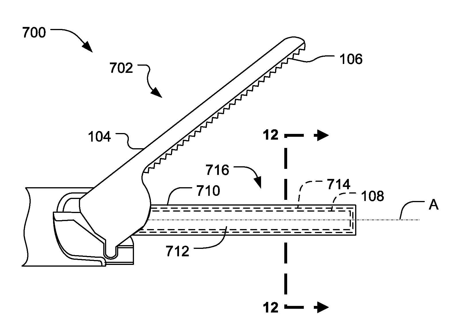
[0061] FIG. 11 illustrates one embodiment of a multi-element end-effector 700. In the illustrated embodiment, the multi-element end-effector 700 comprises a clamp arm assembly 702, shown in an open position, operatively coupled to an ultrasonic surgical blade 712 (blade). The multiple-element end-effector 700 may be employed in clamping coagulating type ultrasonic instruments, for example. The clamp arm assembly 702 comprises a clamp arm 104 and a tissue pad 106 attached thereto. The blade 712 is an ultrasound-propagating element suitable for use in ultrasonic surgical instruments. The body 108, as previously discussed with reference to FIGS. 1-10, forms a portion of the blade 712. As previously discussed, the body 108 comprises a proximal end and a distal end defining an elongated treatment region. The proximal end is adapted and configured to couple to an ultrasonic transducer either directly or through an ultrasonic transmission waveguide. The distal end and the treatment region are used to effect tissue (e.g., dissect, transect, cut, coagulate).
[0062] FIG. 12 illustrates a cross-sectional view of the ultrasonic blade 712 portion of the multi-element end-effector 700 taken along line 12-12 in FIG. 11. In various embodiments, a coating 716 may be formed on the outer surface of the blade body 108. The coating 716 may comprise one or more layers of materials, surface treatments, and/or combinations thereof. In the illustrated embodiment, a first layer 710 and a second layer 714 are formed on the outer surface of the body 108. In one embodiment, the second layer 714 may be formed over a portion of the first layer 710. The one or more material layers 710, 714 may be formed on the body 108 using any suitable material application technique including techniques discussed herein (e.g., the coating application process developed by ISSC). As shown in FIG. 12, the blade 712 may comprise multiple layers of materials, each of varying thicknesses. The first layer 710 may be formed thicker on the lateral surface portions of the body 108 and may be formed thinner on the top surface portions of the body 108, for example, where the blade 712 contacts the tissue pad 106. A second layer 714 may be formed on the first layer 710. The second layer 714 may be formed thicker on the top surface portion of the body 108 where the blade 712 contacts the tissue pad 106 is relatively thinner on the lateral surface portions of the body 108. In one material application technique, the first layer 710 is applied to the body 108 and the second layer 714 is subsequently applied over on the first layer 710 or, as shown in FIG. 12, over portions of the first layer 710. The first and second layers 710, 714 may comprise any of the polymeric materials, dry film lubricants, ceramics, metals, and metallized ceramics previously discussed with reference to FIGS. 2 and 4. In other embodiments, a primer layer and/or a surface treatment may be applied to the outer surface of the body 108 prior to the application of the first and second layers 710, 714. To the extent that one embodiment of the blade 712 comprises a primer layer, the primer layer may comprise any of the base materials discussed with reference to FIGS. 2 and 4. To the extent that one embodiment of the blade 712 comprises a surface treatment, the surface treatment may be applied in accordance with the techniques previously discussed with reference to FIGS. 2 and 4A.
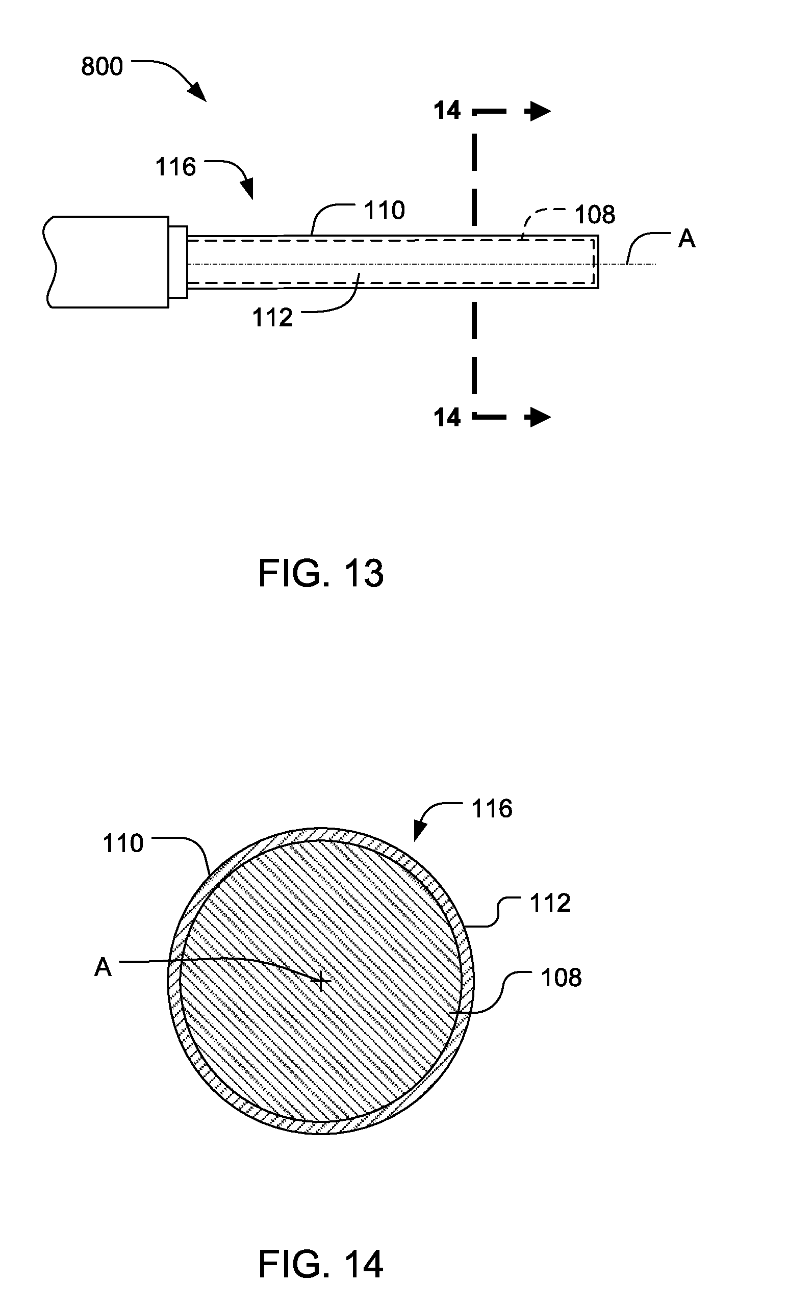
[0063] FIG. 13 illustrates one embodiment of a single element end-effector 800. In one embodiment, the single element end-effector 800 comprises the ultrasonic surgical blade 112 (blade), shown and described with reference to FIGS. 1 and 2. The single-element end-effector 800 may be a scalpel, hook, or ball coagulator, for example. As previously discussed, the coating 116 may be formed on at least a portion of an outer surface of the body 108. The coating 116 also may comprise one or more layers 110 formed on the outer surface of the body 108.
[0064] FIG. 14 illustrates a cross-sectional view of the ultrasonic blade 112 portion of the single element end-effector 800 taken along line 14-14 in FIG. 13. As shown in the cross-sectional view of FIG. 14, in the illustrated embodiment, the blade 112 and the body 108 may have a substantially circular cross sectional shape. In other embodiments, the shape of the blade 112 may be selected according to the type of end-effector used, such as any of the shapes described with reference to FIG. 2.
[0065] FIG. 15 illustrates one embodiment of a multi-element end-effector 900. In the illustrated embodiment, the multi-element end-effector 900 comprises a clamp arm assembly 902, shown in an open position, operatively coupled to an ultrasonic surgical blade 912 (blade). The multiple-element end-effector 900 may be employed in clamping coagulating type ultrasonic instruments, for example. The clamp arm assembly 902 comprises a clamp arm 104 and a tissue pad 106 attached thereto. The blade 912 is an ultrasound-propagating element suitable for use in ultrasonic surgical instruments. The body 108, as previously discussed with reference to FIGS. 1-14, forms a portion of the blade 912. As previously discussed, the body 108 comprises a proximal end and a distal end defining an elongated treatment region. The proximal end is adapted and configured to couple to an ultrasonic transducer either directly or through an ultrasonic transmission waveguide. The distal end and the treatment region are used to effect tissue (e.g., dissect, transect, cut, coagulate). A coating 916 may be formed on at least a portion of an outer surface of the body 108. The coating 916 also may comprise one or more layers 910, 914 formed on the outer surface of the body 108.
[0066] FIG. 16 illustrates a cross-sectional view of the ultrasonic blade 912 portion of the multi-element end-effector 900 taken along line 16-16 in FIG. 15. In various embodiments, the coating 916 may be formed on a portion of the outer surface of the blade body 108. In one embodiment, the coating 916 may comprise a first layer 910 (e.g., primer layer, first layer) and a second layer 914 (e.g., topcoat layer, second layer). In one embodiment, the second layer 914 may be formed over a portion of the first layer 910. The first and second layers 910, 914 may comprise any of the polymeric materials, dry film lubricants, ceramics, metals, and metallized ceramics previously discussed with reference to FIGS. 2 and 4. In other embodiments, a surface treatment may be applied to the outer surface of the body 108 prior to the application of the first and second layers 910, 914. To the extent that one embodiment of the blade 912 comprises a surface treatment, the surface treatment may be applied in accordance with the techniques previously discussed with reference to FIGS. 2 and 4A.
[0067] FIG. 17 illustrates one embodiment of a multi-element end-effector 1000. In the illustrated embodiment, the multi-element end-effector 1000 comprises a clamp arm assembly 1002, shown in an open position, operatively coupled to an ultrasonic surgical blade 1012 (blade). The multiple-element end-effector 1000 may be employed in clamping coagulating type ultrasonic instruments, for example. The clamp arm assembly 1002 comprises a clamp arm 104 and a tissue pad 106 attached thereto. The blade 1012 is an ultrasound-propagating element suitable for use in ultrasonic surgical instruments. The body 108, as previously discussed with reference to FIGS. 1-16, forms a portion of the blade 1012. As previously discussed, the body 108 comprises a proximal end and a distal end defining an elongated treatment region. The proximal end is adapted and configured to couple to an ultrasonic transducer either directly or through an ultrasonic transmission waveguide. The distal end and the treatment region are used to effect tissue (e.g., dissect, transect, cut, coagulate). A coating 1016 may be formed on at least a portion of an outer surface of the body 108. The coating 1016 also may comprise one or more layers 1010, 1014 formed on the outer surface of the body 108.
[0068] FIG. 18 illustrates a cross-sectional view of the ultrasonic blade 1012 portion of the multi-element end-effector 1000 taken along line 18-18 in FIG. 17. In various embodiments, a coating 1016 may be formed on a distal end of the outer surface of the blade body 108. The coating 1016 may comprise a first layer 1010 (e.g., a primer layer, first layer) and a second layer 1014 (e.g., a topcoat layer, second layer) of material, surface treatment, and/or combination thereof. The first and second layers 1010, 1014 may comprise any of the polymeric materials, dry film lubricants, ceramics, metals, and metallized ceramics previously discussed with reference to FIGS. 2 and 4. In other embodiments, a surface treatment may be applied to the outer surface of the body 108 prior to the application of the first and second layers 1010, 1014. To the extent that one embodiment of the blade 1012 comprises a surface treatment, the surface treatment may be applied in accordance with the techniques previously discussed with reference to FIGS. 2 and 4A.
[0069] With reference now to FIGS. 1-18, in various embodiments, the blade 112 (212, 312, 412, 512, 612, 712, 912, 1012) in addition to the shown circular cross sectional shape may have various cross sectional forms or shapes, which may be symmetrical or asymmetrical in nature. For example, the blade may comprise a square, rectangular, triangular, or other polygonal cross-sectional shapes. As previously discussed, in various embodiments, the body 108 also may comprise a variety of symmetrical or asymmetrical shapes. For example, the body 108 may be curved in one or more directions. More details regarding curved or asymmetric blades are described in U.S. Pat. No. 6,283,981, which is incorporated herein by reference.
[0070] In still other embodiments, the body 108 may be configured with a neck or transition portion that protrudes from the proximal end of the treatment region. The neck portion may be configured to attach to an ultrasonic transmission waveguide by a stud, weld, glue, quick connect, or other suitable attachment methods, for example. In various other embodiments, the body 108 and the ultrasonic transmission waveguide may be formed as a single unitary body. In either configuration, the ultrasonic transmission waveguide may have gain steps to amplify the mechanical vibrations transmitted to the body 108 as is well known in the art.
[0071] With reference to FIGS. 1-18, in one embodiment, any of the end-effectors described herein (e.g., blades 112, 212, 312, 412, 512, 612, 712, 912, 1012) may comprise coatings formed of soft or deflectable layers of material to establish frictional engagement (e.g., gripping) with the tissue for improved tissue sealing. Examples of deflectable materials include materials having a durometer hardness of Shore D from about 25 to about 70 Shore units. In other embodiments, the end-effector may include coatings formed of layers of material combined with other technologies such as augmentation via clips and other fasteners. In other embodiments, the end-effector may include a lumen formed through the longitudinal axis A to facilitate suction and removal of expressed fluids from the sealing site to prevent excessive thermal damage to a non-value-added portion of the seal. In other embodiments, the end-effector may include a coating formed of one or more layers of materials that are suitable for use on difficult/hard tissues such as cartilage and bone. In other embodiments, the end-effector may include a surface treatment that has a roughness R.sub.A that is suitable for use on difficult/hard tissues such as cartilage and bone.
[0072] The devices disclosed herein can be designed to be disposed of after a single use, or they can be designed to be used multiple times. In either case, however, the device can be reconditioned for reuse after at least one use. Reconditioning can include any combination of the steps of disassembly of the device, followed by cleaning or replacement of particular pieces, and subsequent reassembly. In particular, the device can be disassembled, and any number of the particular pieces or parts of the device can be selectively replaced or removed in any combination. Upon cleaning and/or replacement of particular parts, the device can be reassembled for subsequent use either at a reconditioning facility, or by a surgical team immediately prior to a surgical procedure. Those skilled in the art will appreciate that reconditioning of a device can utilize a variety of techniques for disassembly, cleaning/replacement, and reassembly. Use of such techniques, and the resulting reconditioned device, are all within the scope of the present disclosure.
[0073] Any of the end-effectors described herein (e.g., blades 112, 212, 312, 412, 512, 612, 712, 912, 1012) may be reconditioned for reuse after at least one use. In one embodiment, reconditioning can include obtaining an ultrasonic surgical blade and applying at least one layer of a first material on at least a portion of the body 108 to form a lubricious coating on the outer surface of the body 108. The lubricious coating may be applied in accordance with any suitable material application techniques, including material application techniques described herein. Then, sterilizing the ultrasonic surgical blade and storing the ultrasonic surgical blade in a sterile container. In another embodiment, reconditioning can include obtaining an ultrasonic surgical blade and forming at least one surface treatment on at least a portion of the body 108 to produce a frictional coating on the outer surface of the body 108. The surface treatment may be applied in accordance with any suitable surface treatment techniques, including the surface treatment techniques described herein. Then, sterilizing the ultrasonic surgical blade and storing the ultrasonic surgical blade in a sterile container.
[0074] Preferably, the various embodiments described herein will be processed before surgery. First, a new or used instrument is obtained and if necessary cleaned. The instrument can then be sterilized. In one sterilization technique, the instrument is placed in a closed and sealed container, such as a plastic or TYVEK.RTM. bag. The container and instrument are then placed in a field of radiation that can penetrate the container, such as gamma radiation, x-rays, or high-energy electrons. The radiation kills bacteria on the instrument and in the container. The sterilized instrument can then be stored in the sterile container. The sealed container keeps the instrument sterile until it is opened in the medical facility.
[0075] It is preferred that the device is sterilized. This can be done by any number of ways known to those skilled in the art including beta or gamma radiation, ethylene oxide, steam. Accordingly, in one embodiment, an ultrasonic surgical blade comprising a body having a proximal end, a distal end, and an outer surface, the distal end is movable relative to a longitudinal axis in accordance with ultrasonic vibrations applied to the proximal end, and a lubricious coating being formed on at least a portion of the outer surface of the body, is obtained. The ultrasonic surgical blade is then sterilized and stored in a sterile container. In another embodiment, an ultrasonic surgical blade comprising a body having a proximal end, a distal end, and an outer surface, the distal end is movable relative to a longitudinal axis by ultrasonic vibrations applied to the proximal end and a predetermined surface treatment having a predetermined surface roughness being formed on at least a portion of the body, is obtained. The ultrasonic surgical blade is then sterilized and stored in a sterile container.
[0076] Although various embodiments have been described herein, many modifications and variations to those embodiments may be implemented. For example, different types of end-effectors may be employed. In addition, combinations of the described embodiments may be used. For example, blade coatings may be formed of any combination of layer materials and surface treatments described herein. Also, where materials are disclosed for certain components, other materials may be used. The foregoing description and following claims are intended to cover all such modification and variations.
[0077] Any patent, publication, or other disclosure material, in whole or in part, that is said to be incorporated by reference herein is incorporated herein only to the extent that the incorporated materials does not conflict with existing definitions, statements, or other disclosure material set forth in this disclosure. As such, and to the extent necessary, the disclosure as explicitly set forth herein supersedes any conflicting material incorporated herein by reference. Any material, or portion thereof, that is said to be incorporated by reference herein, but which conflicts with existing definitions, statements, or other disclosure material set forth herein will only be incorporated to the extent that no conflict arises between that incorporated material and the existing disclosure material.
* * * * *
D00000
D00001
D00002
D00003
D00004
D00005
D00006
D00007
D00008
D00009
D00010
D00011
D00012

D00013

D00014
XML
uspto.report is an independent third-party trademark research tool that is not affiliated, endorsed, or sponsored by the United States Patent and Trademark Office (USPTO) or any other governmental organization. The information provided by uspto.report is based on publicly available data at the time of writing and is intended for informational purposes only.
While we strive to provide accurate and up-to-date information, we do not guarantee the accuracy, completeness, reliability, or suitability of the information displayed on this site. The use of this site is at your own risk. Any reliance you place on such information is therefore strictly at your own risk.
All official trademark data, including owner information, should be verified by visiting the official USPTO website at www.uspto.gov. This site is not intended to replace professional legal advice and should not be used as a substitute for consulting with a legal professional who is knowledgeable about trademark law.