Foldable Electric Bed
Shan; Huafeng ; et al.
U.S. patent application number 16/386257 was filed with the patent office on 2019-08-08 for foldable electric bed. The applicant listed for this patent is Keeson Technology Corporation Limited. Invention is credited to Chuanxiang Ji, Huafeng Shan, Jian Wang.
| Application Number | 20190239653 16/386257 |
| Document ID | / |
| Family ID | 61874792 |
| Filed Date | 2019-08-08 |


| United States Patent Application | 20190239653 |
| Kind Code | A1 |
| Shan; Huafeng ; et al. | August 8, 2019 |
FOLDABLE ELECTRIC BED
Abstract
Disclosed is a foldable electric bed, which includes a head bed frame and a foot bed frame. The head bed frame has a male plate, and the foot bed frame has a female plate. The male plate and the female plate are pin-connected to each other through a pin shaft. One of the head bed frame and the foot bed frame is rotatable relative to the other one thereof by means of the pin shaft between a horizontal position and a folded position. In the folded position, the head bed frame and the foot bed frame are folded together facing each other, and both the head frame and the foot bed frame have gaps for accommodating elements that project from the bed frames.
| Inventors: | Shan; Huafeng; (Jiaxing, CN) ; Wang; Jian; (Jiaxing, CN) ; Ji; Chuanxiang; (Jiaxing, CN) | ||||||||||
| Applicant: |
|
||||||||||
|---|---|---|---|---|---|---|---|---|---|---|---|
| Family ID: | 61874792 | ||||||||||
| Appl. No.: | 16/386257 | ||||||||||
| Filed: | April 17, 2019 |
Related U.S. Patent Documents
| Application Number | Filing Date | Patent Number | ||
|---|---|---|---|---|
| PCT/CN2017/091204 | Jun 30, 2017 | |||
| 16386257 | ||||
| Current U.S. Class: | 1/1 |
| Current CPC Class: | A47C 17/86 20130101; A47C 20/041 20130101; A47C 19/122 20130101 |
| International Class: | A47C 19/12 20060101 A47C019/12 |
Foreign Application Data
| Date | Code | Application Number |
|---|---|---|
| Dec 7, 2016 | CN | 201621334342.8 |
Claims
1. A foldable electric bed, comprising: a head bed frame which comprises a rotatable first bed plank and a head drive assembly for driving the first bed plank to rotate, at least a portion of the head drive assembly projecting from the head bed frame; and a foot bed frame which comprises gaps provided at sides of the foot bed frame, wherein the head bed frame has a projecting male plate, and the foot bed frame has a projecting female plate, wherein the male plate has a pin hole at an end thereof, and the female plate has another pin hole at an end thereof, the pin hole of the male plate and the pin hole of the female plate being matched with each other and pin-connected to each other through a pin shaft, wherein one of the head bed frame and the foot bed frame is rotatable relative to the other one thereof between a horizontal position and a folded position by means of the pin shaft, wherein in the horizontal position, the head bed frame and the foot bed frame are connected adjacent to each other on a same level, wherein in the folded position, the head bed frame and the foot bed frame are folded together facing each other, and at least a portion of the head drive assembly projecting from the head bed frame is disposed in the gaps of the foot bed frame.
2. The foldable electric bed according to claim 1, wherein the foot bed frame comprises a rotatable fourth bed plank and a foot drive assembly for driving the fourth bed plank to rotate, at least a portion of the foot drive assembly projecting from the foot bed frame, and the head bed frame comprises gaps provided at sides of the head bed frame, wherein in the folded position, the head bed frame and the foot bed frame are folded together facing each other, at least a portion of the head drive assembly projecting from the head bed frame is disposed in the gaps of the foot bed frame, and at least a portion of the foot drive assembly projecting from the foot bed frame is disposed in the gaps of the head bed frame.
3. The foldable electric bed according to claim 2, wherein the head bed frame further comprises: a second bed plank fixed in the head bed frame, the second bed plank being hinged to the first bed plank, and the head drive assembly comprises: a first pivotal rod projecting from the head bed frame, a first direct-drive motor, a first drive rod, and a first push rod, wherein the first direct-drive motor is hinged to an end of the head bed frame away from the male plate, two ends of the first drive rod are connected respectively to the first pivotal rod and the first direct-drive motor, and two ends of the first push rod are connected respectively to the first pivotal rod and the first bed plank.
4. The foldable electric bed according to claim 2, wherein the foot bed frame further comprises: a third bed plank fixed in the foot bed frame, a fourth bed plank hinged to the third bed plank, and a fifth bed plank hinged to the fourth bed plank, and the foot drive assembly comprises: a second pivotal rod projecting from the foot bed frame, a second direct-drive motor, a second drive rod, and second push rod, wherein the second direct-drive motor is hinged to an end of the foot bed frame away from the female plate, two ends of the second drive rod are connected respectively to the second pivotal rod and the second direct-drive motor, and two ends of the second push rod are connected respectively to the second pivotal rod and the fourth bed plank.
5. The foldable electric bed according to claim 4, wherein the first direct-drive motor and the second direct-drive motor are respectively disposed on two sides of a longitudinal symmetrical centerline of the electric bed.
6. The foldable electric bed according to claim 1, wherein at least two pairs of the male plates and the female plates are provided at two sides of a longitudinal symmetrical centerline of the electric bed.
7. The foldable electric bed according to claim 1, wherein at least one of the first bed plank, a second bed plank, a third bed plank, a fourth bed plank, and a fifth bed plank has a surface with a hole or a counter bore.
8. The foldable electric bed according to claim 1, wherein the first bed plank and a second bed plank, a third bed plank and a fourth bed plank, and the fourth bed plank and a fifth bed plank, are hinged to each other through three respective hinges, wherein hinges at two sides are made of iron, and hinges in a middle are made of plastic.
9. The foldable electric bed according to claim 1, wherein the foot bed frame further comprises a support leg, which, in the folded position, is supported on the head bed frame.
10. The foldable electric bed according to claim 1, wherein in the folded position, gaps of the head bed frame and the gaps of the foot bed frame deviate from each other by a distance in a horizontal direction.
Description
CROSS REFERENCE TO RELATED APPLICATIONS
[0001] The present application is a Continuation Application of PCT Application No. PCT/CN2017/091204 filed on Jun. 30, 2017, which claims the benefit of Chinese Patent Application No. 201621334342.8 filed on Dec. 7, 2016. All the above are hereby incorporated by reference.
FIELD OF THE TECHNOLOGY
[0002] The present disclosure relates to a foldable electric bed.
BACKGROUND OF THE TECHNOLOGY
[0003] With the improvement of people's living standards, electric beds have found a wide range of applications. Common electric beds are usually designed in one piece. That means a large bed frame is provided fixedly therein with a plurality of mechanical and electric components that are connected through electric wires and cables, and the bed frame is also provided with detachable legs. Such one-piece electric beds are not only structurally complex but also large and heavy. This leads to inconvenience in packaging and transportation and increases difficulty in delivering to users' home. In addition, due to restrictions of residential lifts or stairs, it becomes more difficult to carry such one-piece electrical beds, and intensity of the work is greatly increased. Some electric beds cannot even be carried to users' home by any means. This greatly limits the application of electric beds.
[0004] In existing foldable electric beds, hinges are usually used to connect a head bed frame and a foot bed frame. When the electric bed needs to be folded, components inside the bed and legs of the bed are removed first, and then the head bed frame and the foot bed frame are folded. These components and bed frames are then packaged separately for delivery. When they are delivered to the user's home, professional technicians are sent to the user's home for the installation of the bed, during which a set of spanners are needed for the assembly of the electric bed. This leads to low installation efficiency and an increase of the after-sale service fee.
SUMMARY
[0005] An objective of the present disclosure is to provide a new type of electric bed to overcome at least the above defects.
[0006] In order to achieve the above objective, the present disclosure provides a foldable electric bed, which overcomes the defects of conventional electric beds of being difficult to package, transport, and carry, saves packaging materials and transporting cost, facilitates home-delivery of electric beds, simplifies installation thereof, improves installation efficiency, and decreases the after-service fee.
[0007] The foldable electric bed provided by the present disclosure comprises: a head bed frame, which comprises a rotatable first bed plank and a head drive assembly for driving the first bed plank to rotate, at least a portion of the head drive assembly projecting from the head bed frame; and a foot bed frame, which comprises gaps provided at sides of the foot bed frame. The head bed frame has a projecting male plate, and the foot bed frame has a projecting female plate. The male plate has a pin hole at an end thereof, and the female plate has another pin hole at an end thereof, the pin hole of the male plate and the pin hole of the female plate being matched with each other and pin-connected to each other through a pin shaft. One of the head bed frame and the foot bed frame is rotatable relative to the other one thereof between a horizontal position and a folded position by means of the pin shaft. In the horizontal position, the head bed frame and the foot bed frame are connected adjacent to each other on a same level. In the folded position, the head bed frame and the foot bed frame are folded together facing each other, and at least a portion of the head drive assembly projecting from the head bed frame is disposed in the gaps of the foot bed frame. At this point, the electric bed in the folded position occupies an area that is about half of an area that it occupies in the horizontal position. Besides, because the projecting portion is disposed in the gaps, the folded electric bed has an overall thickness that is only slightly larger than a sum of a thickness of the head bed frame and a thickness of the foot bed frame. This may help to reduce the space occupied by the bed and improve the transporting efficiency thereof.
[0008] In different embodiments according to the present disclosure, one may rely on one and/or more of the following configurations.
[0009] Further, the foot bed frame comprises a rotatable fourth bed plank and a foot drive assembly for driving the fourth bed plank to rotate, at least a portion of the foot drive assembly projecting from the foot bed frame. The head bed frame comprises gaps provided at sides of the head bed frame. In the folded position, the head bed frame and the foot bed frame are folded together facing each other, at least a portion of the head drive assembly projecting from the head bed frame is disposed in the gaps of the foot bed frame, and at least a portion of the foot drive assembly projecting from the foot bed frame is disposed in the gaps of the head bed frame.
[0010] Further, the head bed frame further comprises: a second bed plank fixed in the head bed frame, the second bed plank being hinged to the first bed plank. The head drive assembly comprises: a first pivotal rod projecting from the head bed frame, a first direct-drive motor, a first drive rod, and a first push rod. The first direct-drive motor is hinged to an end of the head bed frame away from the male plate. Two ends of the first drive rod are connected respectively to the first pivotal rod and the first direct-drive motor. Two ends of the first push rod are connected respectively to the first pivotal rod and the first bed plank.
[0011] Further, the foot bed frame further comprises: a third bed plank fixed in the foot bed frame, a fourth bed plank hinged to the third bed plank, and a fifth bed plank hinged to the fourth bed plank. The foot drive assembly comprises: a second pivotal rod projecting from the foot bed frame, a second direct-drive motor, a second drive rod, and second push rod. The second direct-drive motor is hinged to an end of the foot bed frame away from the female plate. Two ends of the second drive rod are connected respectively to the second pivotal rod and the second direct-drive motor. Two ends of the second push rod are connected respectively to the second pivotal rod and the fourth bed plank.
[0012] Further, the first direct-drive motor and the second direct-drive motor are respectively disposed on two sides of a longitudinal symmetrical centerline of the electric bed.
[0013] Further, at least two pairs of the male plates and the female plates are provided at two sides of a longitudinal symmetrical centerline of the electric bed.
[0014] Further, at least one of the first bed plank, a second bed plank, a third bed plank, a fourth bed plank, and a fifth bed plank has a surface with a hole or a counter bore.
[0015] Further, the first bed plank and a second bed plank, a third bed plank and a fourth bed plank, and the fourth bed plank and a fifth bed plank, are hinged to each other through three respective hinges. Hinges at two sides are made of iron, and hinges in the middle are made of plastic.
[0016] Further, the foot bed frame further comprises a support leg, which, in the folded position, is supported on the head bed frame.
[0017] Further, in the folded position, gaps of the head bed frame and the gaps of the foot bed frame deviate from each other by a distance in a horizontal direction.
[0018] Because of these configurations, the foldable electric bed can be folded without removing any assemblies, and can occupy a reduced area that is only about half of the original area. The foldable electric bed overcomes the defects of conventional electric beds of being difficult to package, transport, and carry, saves packaging materials and transporting cost, reduces the size of electric beds and facilitates home-delivery thereof. After the electric bed is carried home, the user only needs to spread flat the head bed frame and the foot bed frame of the electric bed and rotate them to the right position before using the bed. This eliminates the defect in the existing technologies that the removed assemblies or bed legs have to be mounted back to an electric bed by using spanners. The installation efficiency is thus greatly improved, the installation is simplified, and the after-service fee is decreased.
BRIEF DESCRIPTION OF THE DRAWINGS
[0019] It shall be appreciated that in the present disclosure, unless apparent contradictions or incompatibility exist, all the features, variations, and/or specific embodiments may be combined with one another in a number of ways.
[0020] Other features and advantages of the present disclosure will become self-evident by reading the following specifically described nonrestrictive embodiments in conjunction with the accompanying drawings. In the drawings,
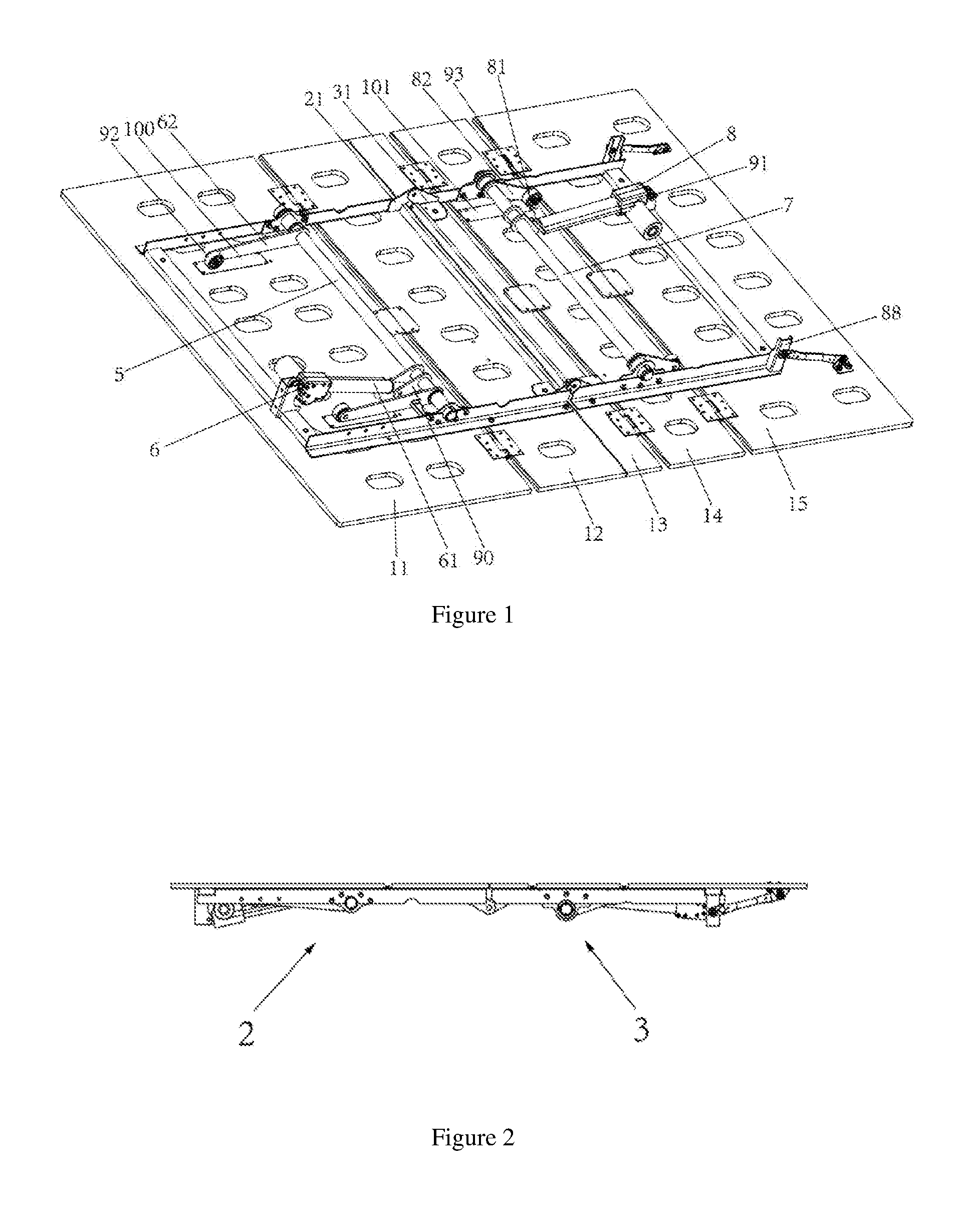
[0021] FIG. 1 schematically shows a perspective view of a structure of a foldable electric bed of the present disclosure in a horizontal position;
[0022] FIG. 2 shows a side view of the foldable electric bed of FIG. 1 in the horizontal position;
[0023] FIG. 3 schematically shows a view of the structure of the foldable electric bed of FIG. 1 in a half-folded position;
[0024] FIG. 4 schematically shows a side view of the structure of the foldable electric bed of FIG. 1 in the half-folded position;
[0025] FIG. 5 shows a view of the assembling of a male plate, a female plate, and a pin shaft in the foldable electric bed of the present disclosure; and
[0026] FIG. 6 is a bottom view of the foldable electric bed of the present disclosure in the horizontal position.
DETAILED DESCRIPTION
[0027] It shall be appreciated that the abovementioned drawings are not drawn to actual scale, and they are merely diagrams of a number of preferred features for illustrating principles of the present disclosure. The design features, such as size, directions, orientations, and shapes disclosed in the present disclosure depend on specific applications and service environments.
[0028] The present disclosure will be illustrated in detail below in conjunction with the embodiments and the accompanying drawings. In these drawings, same reference numbers indicate same or equivalent components of the present disclosure.
[0029] As shown in FIGS. 1 to 6, according to an embodiment of the present disclosure, a foldable electric bed 1 comprises a head bed frame 2 and a foot bed frame 3 which are substantially in a shape of a rectangular frame. The head bed frame 2 comprises two parallel longitudinal rims and two parallel transverse rims that are substantially in a same plane. The foot bed frame 3 also comprises two parallel longitudinal rims and two parallel transverse rims that are substantially in a same plane. The term "longitudinal" refers herein to a length direction of the electric bed, and the term "transverse" herein refers to a width direction of the electric bed.
[0030] The head bed frame 2 further comprises a male plate 21 that projects at an angle against a plane of the head bed frame 2. The foot bed frame 3 further comprises a female plate 31 that projects at an angle against a plane of the foot bed frame 3. Ends of the male plate 21 and the female plate 31 have pin holes that match each other, and are pin-connected to each other by a pin shaft 30. The male plate and the female plate are used in pairs, so that they can connect the head bed frame 2 and the foot bed frame 3 together.
[0031] In particular, the electric bed 1 is provided with at least two pairs of male plates 21 and female plates 31 that are connected to each other through pin shafts 30, and all the pin shafts 30 are arranged in a same straight line. For instance, FIG. 1 shows an example where two pairs of male plates 21 and female plates 31 are symmetrically arranged at two sides of a longitudinal symmetrical centerline of the electric bed 1.
[0032] The male plate 21 and the female plate 31 may be identical or similar elements. Besides, a vertical height of the pin hole of the male plate 21 away from the head bed frame 2 is equal to a vertical height of the pin hole of the female plate 31 away from the foot bed frame 3.
[0033] In addition, the male plate 21 and the female plate 31 are substantially in a shape of a triangle or a crescent.
[0034] Further, the pin shaft 30 is removable, so that it can be replaced after being abraded. Preferably, the pin shaft 30 is arranged along a direction perpendicular to the longitudinal symmetrical centerline of the electric bed 1, as shown in FIG. 5.
[0035] Furthermore, the head bed frame 2 further comprises: a second bed plank 12 that is fixed in the head bed frame 2, a first bed plank 11 that is hinged to the second bed plank 12, and a first pivotal rod 5 that is a part of a head drive assembly. The head drive assembly further comprises the following elements that go with the head bed frame 2: a first direct-drive motor 6, a first drive rod 61, and a first push rod 62. The direct-drive motor 6 is hinged to an end of the head bed frame 2 away from the male plate 21. The first drive rod 61 is hinged at one end thereof to the first pivotal rod 5, and is connected at the other end thereof to the first direct-drive motor 6. The first push rod 62 is fixedly connected at one end thereof to the first pivotal rod 5, and is flexibly connected at the other end thereof to the first bed plank 11.
[0036] By this way, the direct-drive motor 6 may be used to put the first drive rod 61 in motion, and further drive the first pivotal rod 5 to rotate by the action of the first drive rod 61. Because the two ends of the first push rod 62 are connected to the first pivotal rod 5 and the first bed plank 11 respectively, the first plank 11 can thus be driven by the direct-drive motor 6, by means of which the function of lifting and lowering the plank of the electric bed is realized.
[0037] Further, the foot bed frame 3 further comprises: a third bed plank 13 that is fixed in the head bed frame 3, a fourth bed plank 14 that is hinged to the third bed plank 13, a fifth bed plank 15 that is hinged to the fourth bed plank 14, and a second pivotal rod 7 that is a part of a foot drive assembly. The foot drive assembly further comprises the following elements that go with the foot bed frame 3: a second direct-drive motor 8, a second drive rod 81, and a second push rod 82. The second direct-drive motor 8 is hinged to the foot bed frame 3. The second drive rod 81 is hinged at one end thereof to the second pivotal rod 7, and is connected at the other end thereof to the second direct-drive motor 8. The second push rod 82 is fixedly connected at one end thereof to the second pivotal rod 7, and is flexibly connected at the other end thereof to the fourth bed plank 14.
[0038] The first pivotal rod 5 and the second pivotal rod 7 are not limited to be in a shape of a rectangular tube or a cylindrical tube, and may be provided at surfaces of rod bodies thereof with projecting lugs 90, 91, respectively. For example, the first drive rod 61 may be connected at one end thereof to the lug 90 of the first pivotal rod 5. In this way, the first drive rod 61 may drive the first pivotal rod 5 to rotate even without acting directly on the rod body of the first pivotal rod 5, and further drive the first push rod 62 to rotate by the action of the lug 90, thereby realizing the lifting and lowering of the first bed plank 11. The lug increases the moment arm and the moment of force, and can therefore effectively realize the folding of the electric bed.
[0039] Further, the first push rod 62 may be provided at the other end thereof with a wheel 92 which rests on the first bed plank 11. With the flexible contact between the wheel and the first bed flank 11, the abrasion to the bed plank each time the bed plank is lifted can be reduced through a rolling friction. Preferably, the first bed plank 11 may be provided at a back surface thereof with an anti-abrasion piece 100 on which the wheel may roll, so as to further reduce the abrasion and meanwhile reduce noise.
[0040] Similarly, the second push rod 82 may be provided at the other end thereof with a wheel 93 which rests on the fourth bed plank 14. With the flexible contact between the wheel and the fourth bed flank 14, the abrasion to the bed plank each time the bed plank is lifted can be reduced through a rolling friction. Preferably, the fourth bed plank 14 may be provided at a back surface thereof with an anti-abrasion piece 101 on which the wheel may roll, so as to further reduce the abrasion and meanwhile reduce noise.
[0041] Further, the direct-drive motor 6 and the second direct-drive motor 8 are disposed respectively at two sides of the longitudinal symmetrical centerline of the electric bed 1. By doing this, when the head bed frame 2 and the foot bed frame 3 are in a folded position, the direct-drive motor 6 and the second direct-drive motor 8 do not interfere with each other.
[0042] Furthermore, the head bed frame 2 and the foot bed frame 3 are provided with gaps at respective longitudinal rims thereof. The gaps are in a shape of, for example, a semicircle or a rectangle. The gaps on the longitudinal rims of the head bed frame 2 have a size slightly larger than a size of the second pivotal rod 7 located on the foot bed frame 3 and projecting from the plane of the foot bed frame 3. The gaps on the longitudinal rims of the foot bed frame 3 have a size slightly larger than a size of the first pivotal rod 5 located on the head bed frame 2 and projecting from the plane of the head bed frame 2.
[0043] After the head bed frame 2 and the foot bed frame 3 are pin-connected to each other by the pin shaft 30, one of the head bed frame 2 and the foot bed frame 3 may rotate relative to the other one thereof between a horizontal position and a folded position. In the horizontal position, the head bed frame 2 and the foot bed frame 3 are spread out flat adjacent to each other on a same level to form an electric bed for a user to lie. In the folded position, the head bed frame 2 and the foot bed frame 3 are folded together facing each other; the male plate 21 and the female plate 31 separate the head bed frame 2 and the foot bed frame 3 by a very short space where the head drive assembly of the electric bed 1 is enveloped by the head bed frame 2 and the foot bed frame 3; the first pivotal rod 5 projecting from the head bed frame 2 is disposed in the gaps of the foot bed frame 3, and the second pivotal rod 7 projecting from the foot bed frame 3 is disposed in the gaps of the head bed frame 2, which enables the folded electric bed to have a very small overall thickness, thus minimizing the package size of the electric bed and improving the transport efficiency thereof.
[0044] The abovementioned space may be adjusted by adjusting the vertical height of the pin hole away from the bed frame so as to suit different types of electric beds. For instance, when an increase of the space is needed, a male plate and a female plate having a pin hole with a longer vertical height away from the bed frame are used, or on the contrary, a male plate and a female plate having a pin hole with a shorter vertical height away from the bed frame are used.
[0045] In the example as shown in FIG. 1, two support legs 88 are fixed to two corner areas of the foot bed frame away from the head bed frame. In the folded position, the gaps of the head bed frame and the gaps of the foot bed frame deviate from each other by a distance.
[0046] In another embodiment of the present disclosure, the drive assemblies comprise slider motors longitudinally disposed respectively in the head bed frame 2 and the foot bed frame 3, and connecting rods that connect the slider motors and the bed planks. The slider motor is used to drive the connecting rod so as to drive the bed plank to rotate and fold.
[0047] Alternatively, the first bed plank and the second bed plank, the third bed plank and the fourth bed plank, as well as the fourth bed plank and the fifth bed plank, are connected to each other through three respective hinges. The hinges 110 at two sides are made of iron, and the hinges 111 in the middle are made of plastic, so that the electric bed can have a reduced weight.
[0048] The above embodiments serve only as examples and are not used to limit the scope of the present disclosure. Those skilled persons in the art may expect other embodiments capable of achieving same functions based on the above embodiments and within the protection scope of the present disclosure.
[0049] Those skilled persons in the art may master different embodiments, variations, and improvements. In particular, it shall be noted that unless apparent contradictions or incompatibility exist, the above features, variations, and/or specific embodiments of the present disclosure may be combined with one another. All these embodiments and variations as well as improvements shall fall within the protection scope of the present disclosure.
* * * * *
D00000
D00001
D00002
D00003
XML
uspto.report is an independent third-party trademark research tool that is not affiliated, endorsed, or sponsored by the United States Patent and Trademark Office (USPTO) or any other governmental organization. The information provided by uspto.report is based on publicly available data at the time of writing and is intended for informational purposes only.
While we strive to provide accurate and up-to-date information, we do not guarantee the accuracy, completeness, reliability, or suitability of the information displayed on this site. The use of this site is at your own risk. Any reliance you place on such information is therefore strictly at your own risk.
All official trademark data, including owner information, should be verified by visiting the official USPTO website at www.uspto.gov. This site is not intended to replace professional legal advice and should not be used as a substitute for consulting with a legal professional who is knowledgeable about trademark law.