Ultrasonic Touch Detection Through Display
KHAJEH; Ehsan ; et al.
U.S. patent application number 16/256942 was filed with the patent office on 2019-08-01 for ultrasonic touch detection through display. The applicant listed for this patent is Apple Inc.. Invention is credited to Ehsan KHAJEH, Brian Michael KING, George Ho Yin MAK, Aaron Scott TUCKER, Mohammad YEKE YAZDANDOOST, Marcus YIP.
| Application Number | 20190235656 16/256942 |
| Document ID | / |
| Family ID | 67392074 |
| Filed Date | 2019-08-01 |


| United States Patent Application | 20190235656 |
| Kind Code | A1 |
| KHAJEH; Ehsan ; et al. | August 1, 2019 |
ULTRASONIC TOUCH DETECTION THROUGH DISPLAY
Abstract
This relates to system architectures, apparatus and methods for acoustic touch detection (touch sensing) and exemplary applications of the system architectures, apparatus and methods. In some examples, the acoustic touch sensing techniques described herein can be used on a glass surface of a display or touch screen. In some examples, an acoustic touch sensing system can be configured to be insensitive to contact on the device surface by water, and thus acoustic touch sensing can be used for touch sensing in devices that are likely to become wet or fully submerged in water.
| Inventors: | KHAJEH; Ehsan; (San Jose, CA) ; TUCKER; Aaron Scott; (Cupertino, CA) ; KING; Brian Michael; (Saratoga, CA) ; MAK; George Ho Yin; (Santa Clara, CA) ; YIP; Marcus; (San Carlos, CA) ; YEKE YAZDANDOOST; Mohammad; (San Jose, CA) | ||||||||||
| Applicant: |
|
||||||||||
|---|---|---|---|---|---|---|---|---|---|---|---|
| Family ID: | 67392074 | ||||||||||
| Appl. No.: | 16/256942 | ||||||||||
| Filed: | January 24, 2019 |
Related U.S. Patent Documents
| Application Number | Filing Date | Patent Number | ||
|---|---|---|---|---|
| 62624046 | Jan 30, 2018 | |||
| Current U.S. Class: | 1/1 |
| Current CPC Class: | G06F 3/0412 20130101; G06F 2203/04106 20130101; G06F 3/043 20130101; G06F 3/0416 20130101 |
| International Class: | G06F 3/043 20060101 G06F003/043; G06F 3/041 20060101 G06F003/041 |
Claims
1. An apparatus comprising: a cover surface; a display panel coupled to the cover surface; a plurality of bar transducers coupled to the display panel, each bar transducer comprising: a plurality of electrodes coupled to the bar transducer and configured to divide the bar transducer into a plurality of touch sensing pixels; and control circuitry configured to: simultaneously stimulate a first plurality of electrodes coupled to a first bar transducer to produce a shear horizontal wave; and measure a plurality of electrical signals received at each pixel of a first plurality of touch sensing pixels corresponding to the first plurality of electrodes coupled to the first bar transducer.
2. The apparatus of claim 1, wherein the control circuitry is further configured to determine a position of an object in contact with the cover surface based on measured signal values at one or more of the plurality of touch sensing pixels.
3. The apparatus of claim 2, wherein determining the position of the object comprises: receiving a plurality of baseline measurement values for the first plurality of touch sensing pixels, each of the plurality of baseline measurement values corresponding to one touch sensing pixel of the plurality of touch sensing pixels; and comparing each of the measured signal values for the first plurality of touch sensing pixels respectively to the corresponding baseline measurement value of the plurality of baseline measurement values.
4. The apparatus of claim 2 wherein determining the position of the object comprises capturing time of flight information based on the transmitted shear horizontal wave at multiple pixels and determining the position of the object based on the captured time of flight information at the multiple pixels.
5. The apparatus of claim 1, wherein the plurality of bar transducers is configured to operate in a d.sub.24 mode.
6. The apparatus of claim 1, wherein the plurality of bar transducers is configured to operate in a d.sub.15 mode.
7. The apparatus of claim 1, wherein an adhesive layer disposed between the cover surface and the display panel provides an impedance match between the cover surface and the display panel at a frequency of the transmitted shear horizontal wave.
8. A method comprising: stimulating a first bar transducer to transmit a shear horizontal wave through a display stack-up comprising a display panel and a cover surface coupled to the display panel; and measuring a plurality of electrical signals received at each pixel of a first plurality of touch sensing pixels corresponding to a first plurality of electrodes coupled to the first bar transducer.
9. The method of claim 8, further comprising determining a position of an object in contact with the cover surface based on measured signal values at one or more of the plurality of touch sensing pixels.
10. The method of claim 9, wherein determining the position of the object comprises: receiving a plurality of baseline measurement values for the first plurality of touch sensing pixels, each of the plurality of baseline measurement values corresponding to one touch sensing pixel of the plurality of touch sensing pixels; and comparing each of the measured signal values for the first plurality of touch sensing pixels respectively to the corresponding baseline measurement value of the plurality of baseline measurement values.
11. The method of claim 9 wherein determining the position of the object comprises capturing time of flight information based on the transmitted shear horizontal wave at multiple pixels and determining the position of the object based on the captured time of flight information at the multiple pixels.
12. The method of claim 8, wherein the plurality of touch sensing pixels comprises a plurality of bar transducers configured to operate in a d.sub.15 mode.
13. The method of claim 8, wherein the plurality of touch sensing pixels comprises a plurality of bar transducers configured to operate in a d.sub.24 mode.
14. The method of claim 8, wherein an adhesive layer disposed between the cover surface and the display panel provides an impedance match between the cover surface and the display panel at a frequency of the transmitted shear horizontal wave.
15. A non-transitory computer readable storage medium having stored thereon a set of instructions that when executed by a processor causes the processor to perform a method comprising: stimulating a first bar transducer to transmit a shear horizontal wave through a display stack-up comprising a display panel and a cover surface coupled to the display panel; and measuring a plurality of electrical signals received at each pixel of a first plurality of touch sensing pixels corresponding to a first plurality of electrodes coupled to the first bar transducer.
16. The non-transitory computer readable storage medium of claim 15, the method further comprising determining a position of an object in contact with the cover surface based on measured signal values at one or more of the plurality of touch sensing pixels.
17. The non-transitory computer readable storage medium of claim 16, wherein determining the position of the object comprises: receiving a plurality of baseline measurement values for the first plurality of touch sensing pixels, each of the plurality of baseline measurement values corresponding to one touch sensing pixel of the plurality of touch sensing pixels; and comparing each of the measured signal values for the first plurality of touch sensing pixels respectively to the corresponding baseline measurement value of the plurality of baseline measurement values.
18. The non-transitory computer readable storage medium of claim 16 wherein determining the position of the object comprises capturing time of flight information based on the transmitted shear horizontal wave at multiple pixels and determining the position of the object based on the captured time of flight information at the multiple pixels.
19. The non-transitory computer readable storage medium of claim 15, wherein the plurality of touch sensing pixels comprises a plurality of bar transducers configured to operate in a d.sub.15 mode.
20. The non-transitory computer readable storage medium of claim 15, wherein the plurality of touch sensing pixels comprises a plurality of bar transducers configured to operate in a d.sub.24 mode.
21. The non-transitory computer readable storage medium of claim 15, wherein an adhesive layer disposed between the cover surface and the display panel provides an impedance match between the cover surface and the display panel at a frequency of the transmitted shear horizontal wave.
Description
CROSS-REFERENCE TO RELATED APPLICATIONS
[0001] This application claims benefit of U.S. Provisional Patent Application No. 62/624,046, filed Jan. 30, 2018, the entire disclosures of which is incorporated herein by reference for all purposes.
FIELD OF THE DISCLOSURE
[0002] This relates generally to touch sensing and, more particularly, to various methodologies and applications of acoustic touch detection.
BACKGROUND OF THE DISCLOSURE
[0003] Many types of input devices are presently available for performing operations in a computing system, such as buttons or keys, mice, trackballs, joysticks, touch sensor panels, touch screens and the like. Touch screens, in particular, have become extremely popular because of their ease and versatility of operation as well as their declining price. Touch screens can include a touch sensor panel, which can be a clear panel with a touch-sensitive surface, and a display device such as a liquid crystal display (LCD) that can be positioned partially or fully behind the panel so that the touch-sensitive surface can cover at least a portion of the viewable area of the display device. Touch screens can allow a user to perform various functions by touching the touch sensor panel using a finger, stylus or other object at a location often dictated by a user interface (UI) being displayed by the display device. In general, touch screens can recognize a touch and the position of the touch on the touch sensor panel, and the computing system can then interpret the touch in accordance with the display appearing at the time of the touch, and thereafter can perform one or more actions based on the touch. In the case of some touch sensing systems, a physical touch on the display is not needed to detect a touch. For example, in some capacitive-type touch sensing systems, fringing electrical fields used to detect touch can extend beyond the surface of the display, and approaching objects may be detected near the surface without actually touching the surface. Capacitive-type touch sensing system, however, can experience reduced performance due to electrically floating objects (e.g., water droplets) in contact with the touch-sensitive surface.
SUMMARY
[0004] This relates to system architectures, apparatus and methods for acoustic touch detection (touch sensing) and exemplary applications of the system architectures, apparatus and methods. Position of an object touching a surface can be determined using time of flight (TOF) bounding box techniques, acoustic image reconstruction techniques, acoustic tomography techniques, attenuation of reflections from an array of barriers, or a two-dimensional piezoelectric receiving array, for example. Acoustic touch sensing can utilize transducers, such as piezoelectric transducers, to transmit ultrasonic waves along a surface and/or through the thickness of an electronic device to the surface. As the ultrasonic wave propagates, one or more objects (e.g., fingers, styli) in contact with the surface can interact with the transmitted wave causing attenuation, redirection and/or reflection of at least a portion of the transmitted wave. Portions of the transmitted wave energy after interaction with the one or more Objects can be measured to determine the touch location(s) of the one or more objects on the surface of the device. For example, one or more transducers (e.g., acoustic transducers) coupled behind the display of a device can be configured to transmit an acoustic wave through the thickness of a device (e.g., through the display stack and/or glass surface) to the surface and can receive a portion of the wave reflected back when the acoustic wave encounters a finger or object touching the surface. The location of the object can be determined, for example, based on the amount of time elapsing between the transmission of the wave and the detection of the reflected wave (e.g., time-of-flight ranging) and/or changes in the amplitude of the reflected wave. Acoustic touch sensing can be used instead of, or in conjunction with, other touch sensing techniques, such as resistive and/or capacitive touch sensing. In some examples, the acoustic touch sensing techniques described herein can be integrated into a display. In some examples, the acoustic touch sensing techniques described herein can be used on a glass surface of a display or touch screen. In some examples, an acoustic touch sensing system can be configured to be insensitive to contact on the device surface by water, and thus acoustic touch sensing can be used for touch sensing in devices that are likely to become wet or fully submerged in water.
BRIEF DESCRIPTION OF THE DRAWINGS
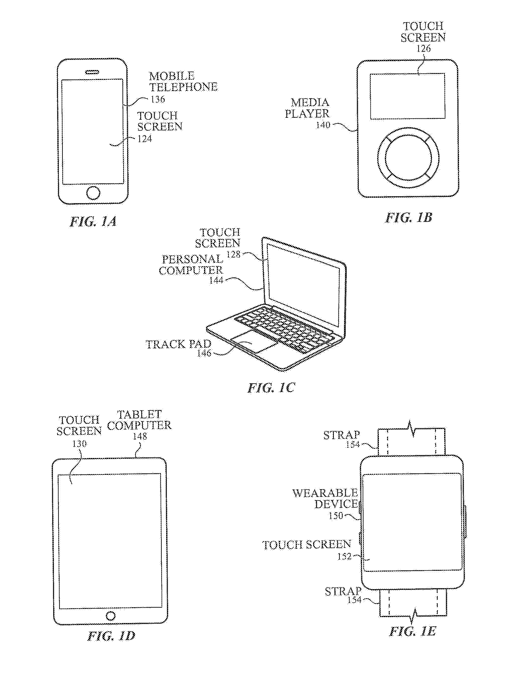
[0005] FIGS. 1A-1E illustrate exemplary electronic devices that can include an acoustic touch sensing system according to examples of the disclosure.
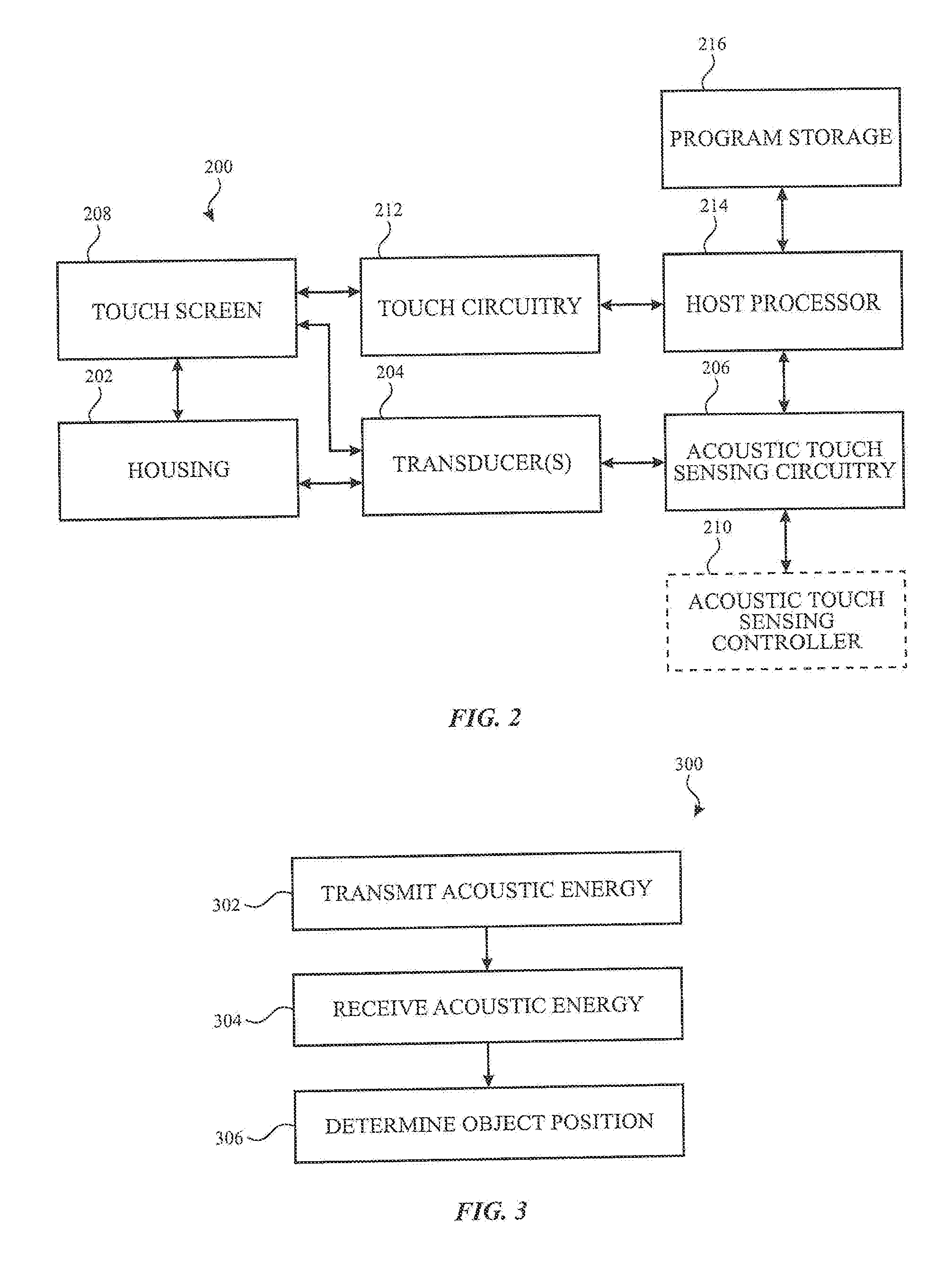
[0006] FIG. 2 illustrates an exemplary block diagram of an electronic device including an acoustic touch sensing system according to examples of the disclosure.
[0007] FIG. 3 illustrates an exemplary method for acoustic touch sensing to determine a position of an object in contact with a surface according to examples of the disclosure.
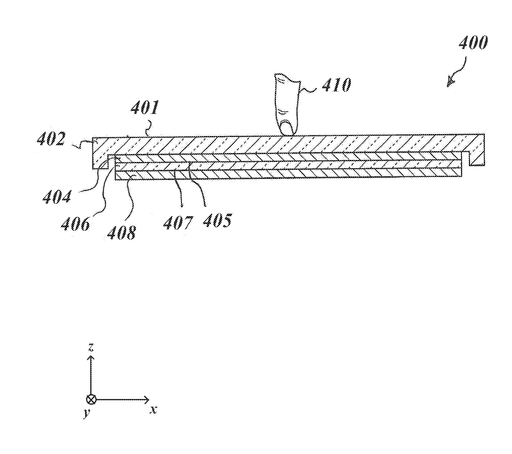
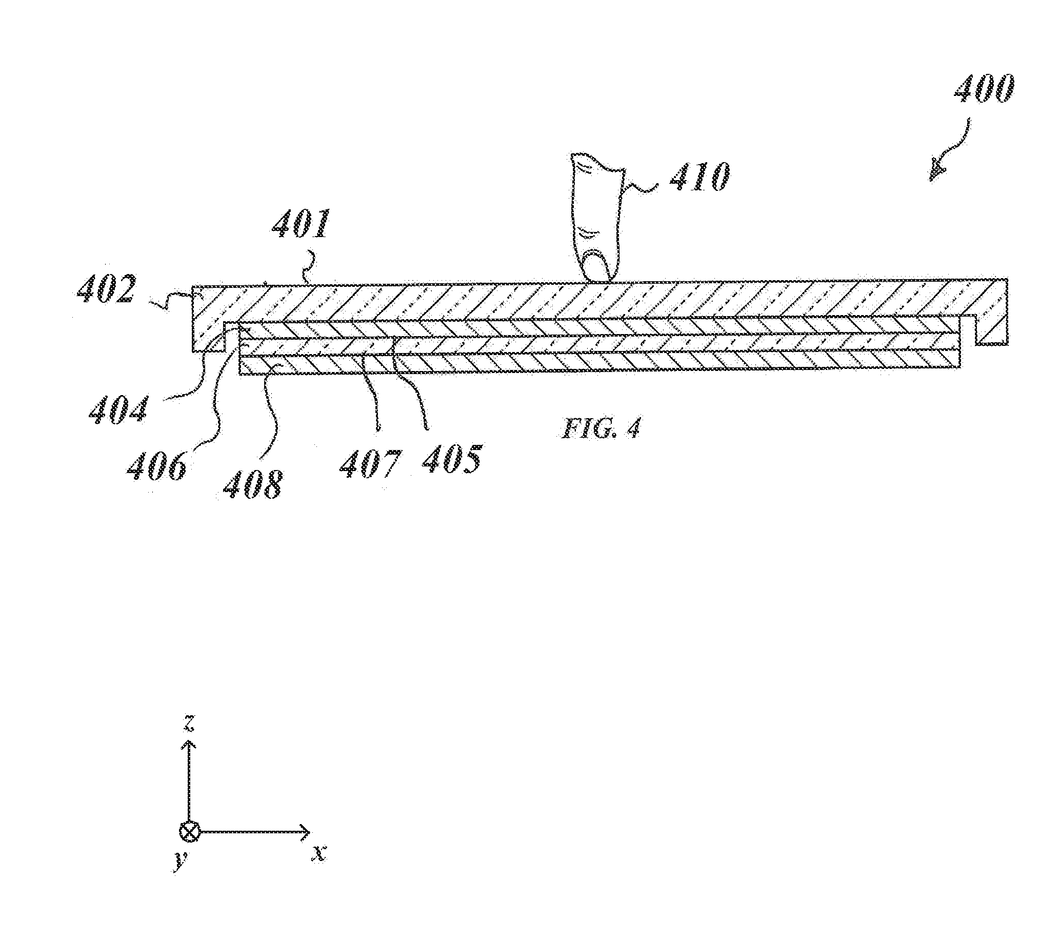
[0008] FIG. 4 illustrates an exemplary acoustic touch sensing system stack-up according to examples of the disclosure.
[0009] FIG. 5 illustrates an exemplary transducer according to examples of the disclosure.
[0010] FIG. 6 illustrates an exemplary transducer and electrode configuration for acoustic touch sensing according to examples of the disclosure.
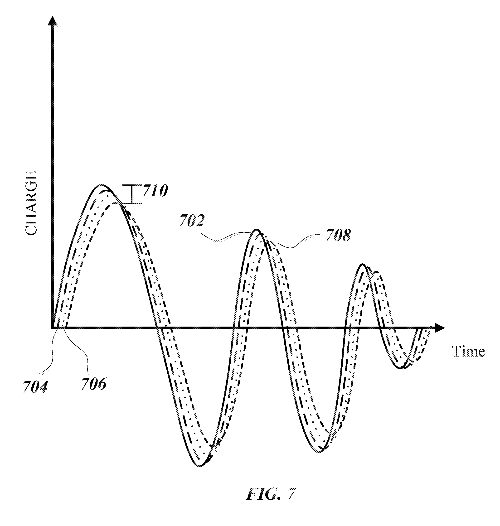
[0011] FIG. 7 illustrates an exemplary timing diagram for acoustic touch sensing according to examples of the disclosure.
DETAILED DESCRIPTION
[0012] In the following description of various examples, reference is made to the accompanying drawings which form a part hereof, and in which it is shown by way of illustration specific examples that can be practiced. It is to be understood that other examples can be used and structural changes can be made without departing from the scope of the various examples.
[0013] FIGS. 1A-1E illustrate examples of systems with touch screens that can include acoustic sensors for detecting contact between an object (e.g., a finger or stylus) and a surface of the system. FIG. 1A illustrates an exemplary mobile telephone 136 that includes a touch screen 124 and can include an acoustic touch sensing system according to examples of the disclosure. FIG. 1B illustrates an example digital media player 140 that includes a touch screen 126 and can include an acoustic touch sensing system according to examples of the disclosure. FIG. 1C illustrates an example personal computer 144 that includes a touch screen 128 and a track pad 146, and can include an acoustic touch sensing system according to examples of the disclosure. FIG. 1D illustrates an example tablet computing device 148 that includes a touch screen 130 and can include an acoustic touch sensing system according to examples of the disclosure. FIG. 1E illustrates an example wearable device 150 (e.g., a watch) that includes a touch screen 152 and can include an acoustic touch sensing system according to examples of the disclosure. Wearable device 150 can be coupled to a user via strap 154 or any other suitable fastener. It should be understood that the example devices illustrated in FIGS. 1A-1E are provided by way of example, and other types of devices can include an acoustic touch sensing system for detecting contact between an object and a surface of the device.
[0014] Acoustic sensors can be incorporated in the above described systems to add acoustic touch sensing capabilities to a surface of the system. For example, in some examples, a touch screen (e.g., capacitive, resistive, etc.) can be augmented with acoustic sensors to provide a touch sensing capability for use in wet environments or under conditions where the device may get wet (e.g., exercise, swimming, rain, washing hands). In some examples, an otherwise non-touch-sensitive display screen can be augmented with acoustic sensors to provide a touch sensing capability. In such examples, a touch screen can be implemented without the stack-up required for a capacitive touch screen. In some examples, the acoustic sensors can be used to provide touch sensing capability for a non-display surface. For example, the acoustic sensors can be used to provide touch sensing capabilities for a track pad 146, a button, a scroll wheel, part or all of the housing or any other surfaces of the device (e.g., on the front, rear or sides).
[0015] FIG. 2 illustrates an exemplary block diagram of an electronic device including an acoustic touch sensing system according to examples of the disclosure. In some examples, housing 202 of device 200 (which can correspond to devices 136, 140, 144, 148, and 150 above) can be coupled with one or more acoustic transducers 204. In some examples, transducers 204 can be piezoelectric transducers, which can be made to vibrate by the application of electrical signals when acting as a transmitter, and generate electrical signals based on detected vibrations when acting as a receiver. In some examples, the transducers 204 can be formed from a piezoelectric ceramic material (e.g., PZT or KNN) or a piezoelectric plastic material (e.g., PVDF). Similarly, transducers 204 can produce electrical energy as an output when vibrated. In some examples, the transducers 204 can be bonded to the housing 202 by a bonding agent (e.g., a thin layer of stiff epoxy). In some examples, the transducers 204 can be deposited on the surface through processes such as deposition, lithography, or the like. In some examples, the transducers 204 can be bonded to the surface using conductive or non-conductive bonding materials. When electrical energy is applied to the transducers 204 it can cause the transducers to vibrate, the surface material in contact with the transducers can also be caused to vibrate, and the vibrations of the molecules of the surface material can propagate as an acoustic wave through the surface material. In some examples, vibration of the transducers 204 can be used to produce ultrasonic acoustic waves at a selected frequency over a broad frequency range (e.g., 400 kHz-10 MHz) in the medium of the surface of the electronic device which can be metal, plastic, glass, wood, or the like. It should be understood that other frequencies outside of the exemplary range above can be used while remaining within the scope of the present disclosure.
[0016] In some examples, transducers 204 can also be partially or completely disposed under or behind a display 208 (e.g., an Organic Light Emitting Diodes (OLED) display) such that the transducers are not visible to a user. When electrical energy is applied to the transducers 204 it can cause the transducers to vibrate, the display materials in contact with the transducers can also be caused to vibrate, and the vibrations of the molecules of the display materials can propagate as an acoustic wave through them. In some examples, display 208 can be a touch screen (e.g., capacitive) and the transducers 204 can be partially or completely disposed on (or coupled to) a portion of the touch screen display 208. For example, the touch screen display 208 may comprise a glass panel (cover glass), and a display region of the touch screen may be surrounded by a non-display region (e.g., a black border region surrounding the periphery of the display region of touch screen). In some examples, transducers 204 can be disposed partially or completely in the black mask region of the touch screen display 208 glass panel (e.g., on the back side of the glass panel behind the black mask) such that the transducers are not visible (or are only partially visible) to a user.
[0017] Device 200 can further comprise acoustic touch sensing circuitry 206, which can include circuitry for driving electrical signals to stimulate vibration of the transducers 204 (e.g., transmit circuitry), as well as circuitry for sensing electrical signals output by the transducers (e.g., receive circuitry) when the transducer is stimulated by received acoustic energy. In some examples, timing operations for the acoustic touch sensing circuitry 206 can optionally be provided by a separate acoustic touch sensing controller 210 that can control timing of acoustic touch sensing circuitry 206 operations. In some examples, touch sensing controller 210 can be coupled between acoustic touch sensing circuitry 206 and host processor 214. In some examples, controller functions can be integrated with the acoustic touch sensing circuitry 206 (e.g., on a single integrated circuit). Output data from acoustic touch sensing circuitry 206 can be output to a host processor 214 for further processing to determine a location of an object contacting the device as will be described in more detail below. In some examples, the processing for determining location of a contacting object can be performed by the acoustic touch sensing circuitry 206, controller 210 or a separate sub-processor of device 200 (not shown).
[0018] In addition to acoustic touch sensing, the device can include additional touch circuitry 212 and optionally a touch controller (not shown) that can be coupled to the touch screen display 208. In examples including a touch controller, the touch controller can be disposed between the touch circuitry 212 and the host processor 214. The touch circuitry 212 can, for example, be capacitive or resistive touch sensing circuitry, and can be used to detect contact and/or hovering of objects (e.g., fingers, styli) in contact with and/or in proximity to the touch screen display 208, particularly in the display region of the touch screen. Thus, device 200 can include multiple types of sensing circuitry (e.g., touch circuitry 212 and acoustic touch sensing circuitry 206) for detecting objects (and their positions) in different regions of the device and/or for different purposes, as will be described in more detail below. Although described herein as including a touch screen, it should be understood that touch circuitry 212 can be omitted and touch screen display 208 can be replaced by an otherwise non-touch-sensitive display (e.g., but-for the acoustic touch sensors).
[0019] Host processor 214 can receive acoustic or other touch outputs (e.g., capacitive) and perform actions based on the touch outputs. Host processor 214 can also be connected to program storage 216 and touch screen display 208. Host processor 214 can, for example, communicate with touch screen display 208 to generate an image on touch screen display 208, such as an image of a UI, and can use touch sensing circuitry 212 and/or acoustic touch sensing circuitry 206 (and, in some examples, their respective controllers) to detect a touch on or near touch screen display 208, such as a touch input to the displayed UI. The touch input can be used by computer programs stored in program storage 216 to perform actions that can include, but are not limited to, moving an object such as a cursor or pointer, scrolling or panning, adjusting control settings, opening a file or document, viewing a menu, making a selection, executing instructions, operating a peripheral device connected to the host device, answering a telephone call, placing a telephone call, terminating a telephone call, changing the volume or audio settings, storing information related to telephone communications such as addresses, frequently dialed numbers, received calls, missed calls, logging onto a computer or a computer network, permitting authorized individuals access to restricted areas of the computer or computer network, loading a user profile associated with a user's preferred arrangement of the computer desktop, permitting access to web content, launching a particular program, encrypting or decoding a message, and/or the like. Host processor 214 can also perform additional functions that may not be related to touch processing.
[0020] Note that one or more of the functions described herein can be performed by firmware stored in memory and executed by the touch circuitry 212 and/or acoustic touch sensing circuitry 206 (or their respective controllers), or stored in program storage 216 and executed by host processor 214. The firmware can also be stored and/or transported within any non-transitory computer-readable storage medium for use by or in connection with an instruction execution system, apparatus, or device, such as a computer-based system, processor-containing system, or other system that can fetch the instructions from the instruction execution system, apparatus, or device and execute the instructions. In the context of this document, a "non-transitory computer-readable storage medium" can be any medium (excluding a signal) that can contain or store the program for use by or in connection with the instruction execution system, apparatus, or device. The non-transitory computer-readable storage medium can include, but is not limited to, an electronic, magnetic, optical, electromagnetic, infrared, or semiconductor system, apparatus or device, a portable computer diskette (magnetic), a random access memory (RAM) (magnetic), a read-only memory (ROM) (magnetic), an erasable programmable read-only memory (EPROM) (magnetic), a portable optical disc such a CD, CD-R, CD-RW, DVD, DVD-R, or DVD-RW, or flash memory such as compact flash cards, secured digital cards, USB memory devices, memory sticks, and the like.
[0021] The firmware can also be propagated within any transport medium for use by or in connection with an instruction execution system, apparatus, or device, such as a computer-based system, processor-containing system, or other system that can fetch the instructions from the instruction execution system, apparatus, or device and execute the instructions. In the context of this document, a "transport medium" can be any medium that can communicate, propagate or transport the program for use by or in connection with the instruction execution system, apparatus, or device. The transport readable medium can include, but is not limited to, an electronic, magnetic, optical, electromagnetic or infrared wired or wireless propagation medium.
[0022] It is to be understood that device 200 is not limited to the components and configuration of FIG. 2, but can include other or additional components in multiple configurations according to various examples. Additionally, the components of device 200 can be included within a single device or can be distributed between multiple devices. Additionally, it should be understood that the connections between the components are exemplary and different unidirectional or bidirectional connections that can be included between the components depending on the implementation, irrespective of the arrows shown in the configuration of FIG. 2.
[0023] FIG. 3 illustrates an exemplary method 300 for acoustic touch sensing of an object contact position according to examples of the disclosure. At 302, acoustic energy can be transmitted (e.g., by one or more transducers 204) through a stack-up that can include a display and/or any other layers (e.g., cover glass, bonding layer(s)) to a surface of a device in the form of an ultrasonic wave. In some examples, the wave can propagate as a compressive wave, a shear horizontal wave, a Rayleigh wave, a Lamb wave, a Love wave, a Stoneley wave, or a surface acoustic wave. Other propagation modes for the transmitted acoustic energy can also exist based on the properties of the display, surface material, and any intermediate layers, and the manner of energy transmission from the transducers to the surface of the device. In some examples, the surface can be formed from glass or sapphire crystal (e.g., display 208) or the surface can be formed from metal, plastic, or wood (e.g., housing 202). Transmitted energy can propagate through the display to the surface of the device until a discontinuity in the surface is reached, which can cause a portion of the energy to reflect. In some examples, a discontinuity can occur at edges of the surface material (e.g., when the ultrasonic wave propagates to the edge of the surface opposite the transducer). In some examples, a discontinuity can be an irregularity in the shape of the surface (e.g., a groove or pattern etched into the surface). In some examples, a discontinuity can be a reflective material coupled to the surface (e.g., deposited). In some examples, an object in contact with the surface (e.g., a user's finger) can also be a discontinuity. When the transmitted energy reaches one of the discontinuities described above, some of the energy can be reflected, and a portion of the reflected energy can be directed to the one or more transducers 204. In some examples, the propagation mode of acoustic energy can be selected such that water or other fluids in contact with the surface of the device (e.g., device 200) will not interact with the acoustic waves, and thus can be invisible to the acoustic sensing technique. In some examples, an exemplary the acoustic touch sensing method can be effective for detecting the presence of an object (e.g., a user's finger) even in the presence of water drops (or other low-viscosity fluids) on the surface of the device or even while the device is fully submerged.
[0024] At 304, returning acoustic energy can be received, and the acoustic energy can be converted to an electrical signal by one or more transducers 204. At 306, the acoustic sensing system can determine whether one or more objects is contacting the surface of the device, and can further detect the position of one or more objects based on the received acoustic energy. In some examples, a distance of the object from the transmission source (e.g., transducers 204) can be determined from a TOF between transmission and reception of reflected energy, and a propagation rate of the ultrasonic wave through the material. In some examples, TOF measurements from multiple transducers at different positions can be used to triangulate or trilaterate object position. In some examples, baseline reflected energy from one or more intentionally included discontinuities (e.g., barriers, ridges, grooves, etc.) can be compared to a measured value of reflected energy. The baseline reflected energy can be determined during a measurement when no object (e.g., finger) is in contact with the surface. In some examples, reflected energy can be measured at different positions relative to the surface (e.g., at touch pixels as will be described further below). A position of measured deviations of the reflected energy from the baseline can be correlated with a location of an object. Although method 300, as described above, generally refers to reflected waves received by the transducers that transmitted the waves, in some examples, the transmitter and receiver functions can be separated such that the transmission of acoustic energy at 302 and receiving acoustic energy at 304 may not occur at the same transducer. Exemplary device configurations and measurement timing examples that can be used to implement method 300 will be described in further detail below.
[0025] FIG. 4 illustrates an exemplary cross-sectional view of acoustic touch sensing system stack-up 400 including cover glass 402 (e.g., front crystal), display 406 (e.g., OLED), and transducer(s) 408. While the illustrated stack-up 400 in FIG. 4 is exemplary, it should be understood that in some examples, the stack-up 400 can include additional layers without departing from the scope of the present disclosure. In some examples, cover glass 402 can be mounted on a first side 405 of display 406 and transducer 408 can be mounted on a second side 407 of display 406 (e.g., under or behind display 406). In some examples, transducer 408 can be mounted between the cover glass and the transducer 408 can be configured to generate acoustic waves (e.g., shear horizontal waves) that propagate through the stack-up (e.g., through display 406, adhesive 404, and cover glass 402) to the surface 401 of cover glass 402 and to receive the reflected acoustic waves from the surface 401 of cover glass 402 and/or from object 410 (e.g., a finger or stylus). In some examples, an adhesive 404 (e.g., liquid optically clear adhesive (LOCA)) can be used to affix the display 406 to cover glass 402. In some examples, the impedance characteristic of the adhesive 404 material can have a significant impact on transmission of acoustic waves through the touch sensing system stack-up. For example, a hard epoxy can be used as the adhesive 404 in order to provide impedance matching at both the front crystal 402/adhesive interface and at the adhesive/display 406 interface. In some examples, a poor impedance match between layers can result in a reduction in the amplitude of the acoustic waves (e.g., shear horizontal wave) that are transmitted to the front surface of the cover glass 402, and increases the amplitude of the acoustic waves reflected back toward the transducer 408. It should be understood that although illustrated single transducers are illustrated as performing both transmit and receive functions (i.e., transceivers), in some examples, the transmit and receive functions can be performed by separate transducers (e.g., by two transducers in proximity to one another, rather than one transmit and receive transducer).
[0026] When an object 410 is touching the cover glass 402 (e.g., a touch condition), the object 410 can absorb and/or reflect a portion of the transmitted shear wave. Furthermore, the object 410 can change the impedance seen by the transducer relative to when there is no object in contact with the cover glass 402. Accordingly, several different sensing techniques can be used to detect the presence and location of an object. In a first exemplary sensing technique, TOF can be used to determine the presence of object 410 (e.g., a touch event on the surface 401 of the cover glass 402). The TOF measurement can be carried out by measuring the time between transmission of the shear horizontal wave and detection of returned energy from the shear horizontal wave. If the shear horizontal wave interacts with an object (e.g., finger 410) on the surface 401 of the cover glass 402, a portion of the incident energy can reflect and return to the transducer 408 and/or other nearby transducers (or pixels, as described further below). The amount of time (e.g., TOF) and the speed of propagation of the wave can be used to determine the distance of the object from the origin point of the transmitted wave. The TOF of the reflected wave when no object 410 is touching the cover glass 402 can be used as a baseline for comparing the time of flight of reflected energy from an object 410. In a second exemplary sensing technique, absorption of a portion of the transmitted energy by an object 410 can be used to determine the presence of an object. In some examples where the reflected energy can be received at multiple locations (e.g., pixels) simultaneously, the location of the touch event can then be determined by triangulating or trilaterating the received signals at the different locations. In some examples, a baseline amplitude (or energy) of reflected acoustic waves from the surface 401 of cover glass 402 can be determined for a no-touch condition. If a portion of the transmitted wave is absorbed by an object 410 in contact with the cover glass 402, the change in amplitude (or energy) in the reflected wave can be used to detect the presence of the object. In a third exemplary detection technique, a baseline impedance of the stack-up 400 can be determined for a no-touch condition, such that changes in impedance caused by an object 410 in contact with the cover glass 402 can be measured.
[0027] FIG. 5 illustrates an exemplary transducer 500 (e.g., corresponding to transducer 408 above) according to examples of the disclosure. As noted above, a shear horizontal wave may not interact with water present on the surface of a cover glass (e.g., 402 above). In some examples, waves of the lowest shear horizontal mode (SH0) can be produced by operating a piezoelectric transducer in either a d.sub.15 mode or a d.sub.24 mode. In the example illustrated in FIG. 5, the transducer can be operated in a d.sub.24 mode to produce a shear horizontal wave that propagates in the direction of the z-axis (e.g., through the display and cover glass). In addition to the shear horizontal wave, a Lamb wave can be produced by the shearing displacement that propagates along the x-axis direction (e.g., both to the left and right). The d.sub.24 mode of operation can be accomplished by stimulating electrodes places on sides 502 and 504 of transducer 500 and with poling direction 506 of the transducer along the x-axis direction (e.g., "3" axis of the crystal lattice structure). In order for the acoustic wave to travel through the full thickness of the display stack up to the surface of the front crystal and reflect back to the transducer, a low frequency acoustic wave (e.g., 1 MHz or lower) may be generated. In the d.sub.24 mode of operation, the frequency of the shear horizontal wave can be inversely proportional to on the distance between the electrodes 502 and 504 (e.g., distance "d"). Accordingly, in order to lower the frequency of the shear wave, the distance d must be increased. Such an adjustment of the distance d would not require a corresponding increase in the thickness t. Thus, in some examples, this configuration would allow transducer 500 to drive a signal at a desired frequency independent of thickness "t" of the transducer 500. In some examples, this thickness independence for operating frequency can allow for thickness selection of the transducer 500 based primarily on the required signal strength to obtain a desired signal to noise ratio (SNR) as well as a desired total thickness for the display stack-up (e.g., 400 above). Although FIG. 5 illustrates a transducer with single electrodes 502 and 504 on opposing sides, it should be understood that the transducer can be divided into individual pixels by providing separate electrodes on different sections of the transducer. In some examples, one of the electrodes 502/504 can remain continuous along the full length and serve as a common electrode, while the opposing electrode 504/502 can be pixelated. An exemplary pixelated electrode arrangement will be described in more detail in connection with FIG. 6 below.
[0028] In some alternative examples, a transducer operating in a d.sub.15 mode can also be used to produce shear horizontal waves that propagate in the z-axis direction. In some examples, the d.sub.15 mode can be achieved by moving the electrodes 502 and 504 to the top and bottom sides of the transducer 500 with the same poling direction 506. In such a configuration, a shear horizontal mode wave can be created to propagate in the z-axis direction similar to the d.sub.24 mode described above. Unlike the d.sub.24 mode, in the case of the d.sub.15 mode, the frequency of operation is inversely proportional to the thickness "t" of the transducer 500. Thus, in order to reduce the frequency of a transmitted wave, the thickness "t" can be increased. For an exemplary frequency of 1 MHz, the thickness of the transducer can be around about 1 mm and for an exemplary frequency of 0.5 MHz, the thickness of the transducer can be around about 2 mm. Thus, for low frequencies the thickness required to achieve the proper frequency can become prohibitively large. While thinner transducers are possible with the use of a higher frequency (e.g., 5 MHz), higher frequencies can experience greater attenuation resulting in a reduction of signal strength from reflected waves received at the transducer 500.
[0029] FIG. 6 illustrates a top view of an exemplary acoustic touch sensing system configuration 600 including cover glass 602 (e.g., corresponding to cover glass 402) (e.g., front crystal), display 606 (e.g., corresponding to display 406), and transducers 608 (e.g., corresponding to transducer 408). Configuration 600 also illustrates pixelated electrodes 604 and gaps 610 between the electrodes that can be used to form separate sensing pixels for the acoustic touch sensor. In the illustration, the display region 606 is shown without shading so that the transducers 608 as well as the pixelated electrodes 604 and gaps 610 can be more easily distinguished. In some examples, each of the pixelated electrodes 604 of a particular transducer 608 can be simultaneously driven (e.g., during a transmission) and accordingly the entire length of each transducer 608 produce a plane shear horizontal wave that propagates through the stack-up (e.g., stack-up 400 above) through the z-axis direction. In some examples, a subset of the pixelated electrodes 604 of a single transducer 608 can be simultaneously driven. As mentioned above, if the transistor is operated in the d.sub.24 mode, lamb waves may also be produced at the ends of the transducer bars, which may result in an increased sensitivity to the presence of water on the cover glass 602 in the proximity of the pixelated electrodes 604 located proximate to either end of the bar transducer 608. Accordingly, the elongated shape of transducers 608 can reduce the presence and effects of compressional waves (e.g., a component of a generated Lamb wave) toward the center of each transducer. As such, configuration 600 can reduce false positive measurements of touch due to water or other viscous fluids on the surface of a device (e.g., will not confuse water on the cover glass as a touch condition). In some examples, each of the bar transducers 608 can be driven serially to perform a row-by-row scan of touch on the cover glass 602. In some examples, bar transducers 608 can be driven in groups of two or more. In some examples, groups of bar transducers 608 that are simultaneously driven can be separated by one or more inactive rows to prevent interference between the acoustic waves created at each of the driven bar transducers. In some examples, the width of transducers can extend to the edges of display 604 and/or the edges of cover glass 602 (e.g., extend the full width of the display 604 and/or cover glass 602). In some examples, the display 604 can extend to the full area of cover glass 602, as the transducer-based touch sensing is operable on and/or near metal surfaces unlike some other touch sensing techniques such as capacitive touch sensing.
[0030] FIG. 7 illustrates an exemplary timing diagram for acoustic touch sensing according to examples of the disclosure. FIG. 7 illustrates a plurality of waveforms 702-708 that can represent a transducer charge output versus time. Signal 702 can correspond to the acoustic energy received at a pixel of the transducer (e.g., reflected back from the surface of the cover glass 402 and/or 602 above) without a touch condition (e.g., without an object on the surface of the cover glass). In some examples, signal 702 can correspond to the baseline amplitude of reflected acoustic waves described above with reference to FIG. 4. This baseline amplitude of reflected acoustic waves can also be indicative of the impedance seen by the transducer without any nearby touching object. In some examples, particularly where the transmitted acoustic wave from the transducer is a shear horizontal wave, water on the surface of the cover glass near the particular touch pixel (e.g., pixel 604 above) does not interact with the shear horizontal wave, and accordingly the baseline signal 702 is unaltered even in the presence of water. Waveform 708 can correspond to the acoustic energy at the transducer received from the wave reflected off of an object (e.g., corresponding to object 410) on or near the surface of the cover glass. In particular, the object touching the surface of the cover glass can absorb/and or reflect a portion of the acoustic wave transmitted from the transducer. As a result, the peak amplitude of the waveform 708 can be reduced since less of the energy is returned to the transducer. The difference 710 between the peak amplitude of the baseline waveform 702 and the waveform 708 can be used to detect a touch condition as described above with reference to FIG. 4. In addition, FIG. 7 illustrates a phase shift in the waveform 708 that can occur relative to the baseline waveform 702 as a result of interactions between the shear wave and the touching object that can further be used to detect a touch condition. In some examples, a combination of the amplitude change and phase change in the waveform 708 can be used as a measure of the impedance seen by the transistor for detecting the presence of an object. In some examples, a change in amplitude, phase, and/or impedance can be compared to a threshold change to distinguish between a touching condition and a non-touching condition.
[0031] Therefore, according to the above, some examples of the disclosure are directed to an apparatus comprising: a cover surface, a display panel coupled to the cover surface, a plurality of bar transducers coupled to the display panel, each bar transducer comprising: a plurality of electrodes coupled to the bar transducer and configured to divide the bar transducer into a plurality of touch sensing pixels, and control circuitry configured to: simultaneously stimulate a first plurality of electrodes coupled to a first bar transducer to produce a shear horizontal wave and measure a plurality of electrical signals received at each pixel of a first plurality of touch sensing pixels corresponding to the first plurality of electrodes coupled to the first bar transducer. Additionally or alternatively to one or more of the examples disclosed above, in some examples, the control circuitry is further configured to determine a position of an object in contact with the cover surface based on measured values at one or more of the plurality of touch sensing pixels. Additionally or alternatively to one or more of the examples disclosed above, in some examples, determining the position of the object comprises: receiving a baseline measurement value for each of the first plurality of touch sensing pixels; and comparing each of the measured values at the one or more of the plurality of touch sensing pixels respectively to the baseline measurement value. Additionally or alternatively to one or more of the examples disclosed above, in some examples, the plurality of bar transducers is configured to operate in a d.sub.24 mode. Additionally or alternatively to one or more of the examples disclosed above, in sonic examples, the plurality of bar transducers is configured to operate in a d.sub.15 mode. Additionally or alternatively to one or more of the examples disclosed above, in some examples, the position of the object comprises capturing time of flight information based on the transmitted shear horizontal wave at multiple pixels and determining the position of the object based on the captured time of flight information at the multiple pixels. Additionally or alternatively to one or more of the examples disclosed above, in some examples, an adhesive layer disposed between the cover surface and the display panel provides an impedance match for a shear horizontal wave at a frequency of the transmitted shear horizontal wave.
[0032] Some examples of the disclosure are directed to a method comprising: stimulating a first bar transducer to transmit a shear horizontal wave through a display stack-up comprising a display panel and a cover surface coupled to the display panel, and measuring a plurality of electrical signals received at each pixel of a first plurality of touch sensing pixels corresponding to a first plurality of electrodes coupled to the first bar transducer.
[0033] Some examples of the disclosure are directed to a non-transitory computer readable storage medium having stored thereon a set of instructions that when executed by a processor causes the processor to: stimulate a first bar transducer to transmit a shear horizontal wave through a display stack-up comprising a display panel and a cover surface coupled to the display panel, and measure a plurality of electrical signals received at each pixel of a first plurality of touch sensing pixels corresponding to a first plurality of electrodes coupled to the first bar transducer.
[0034] Although examples of this disclosure have been fully described with reference to the accompanying drawings, it is to be noted that various changes and modifications will become apparent to those skilled in the art. Such changes and modifications are to be understood as being included within the scope of examples of this disclosure as defined by the appended claims.
* * * * *
D00000
D00001
D00002
D00003
D00004
D00005
D00006
XML
uspto.report is an independent third-party trademark research tool that is not affiliated, endorsed, or sponsored by the United States Patent and Trademark Office (USPTO) or any other governmental organization. The information provided by uspto.report is based on publicly available data at the time of writing and is intended for informational purposes only.
While we strive to provide accurate and up-to-date information, we do not guarantee the accuracy, completeness, reliability, or suitability of the information displayed on this site. The use of this site is at your own risk. Any reliance you place on such information is therefore strictly at your own risk.
All official trademark data, including owner information, should be verified by visiting the official USPTO website at www.uspto.gov. This site is not intended to replace professional legal advice and should not be used as a substitute for consulting with a legal professional who is knowledgeable about trademark law.