Systems and Methods for Manufacturing Camera Modules Using Active Alignment of Lens Stack Arrays and Sensors
Duparre; Jacques ; et al.
U.S. patent application number 16/382099 was filed with the patent office on 2019-08-01 for systems and methods for manufacturing camera modules using active alignment of lens stack arrays and sensors. This patent application is currently assigned to FotoNation Limited. The applicant listed for this patent is FotoNation Limited. Invention is credited to Jacques Duparre, Dan Lelescu, Andrew Kenneth John McMahon.
| Application Number | 20190235138 16/382099 |
| Document ID | / |
| Family ID | 49777764 |
| Filed Date | 2019-08-01 |


| United States Patent Application | 20190235138 |
| Kind Code | A1 |
| Duparre; Jacques ; et al. | August 1, 2019 |
Systems and Methods for Manufacturing Camera Modules Using Active Alignment of Lens Stack Arrays and Sensors
Abstract
Systems and methods in accordance with embodiments of the invention actively align a lens stack array with an array of focal planes to construct an array camera module. In one embodiment, a method for actively aligning a lens stack array with a sensor that has a focal plane array includes: aligning the lens stack array relative to the sensor in an initial position; varying the spatial relationship between the lens stack array and the sensor; capturing images of a known target that has a region of interest using a plurality of active focal planes at different spatial relationships; scoring the images based on the extent to which the region of interest is focused in the images; selecting a spatial relationship between the lens stack array and the sensor based on a comparison of the scores; and forming an array camera subassembly based on the selected spatial relationship.
| Inventors: | Duparre; Jacques; (Jena, DE) ; McMahon; Andrew Kenneth John; (San Carlos, CA) ; Lelescu; Dan; (Morgan Hill, CA) | ||||||||||
| Applicant: |
|
||||||||||
|---|---|---|---|---|---|---|---|---|---|---|---|
| Assignee: | FotoNation Limited Galway IE |
||||||||||
| Family ID: | 49777764 | ||||||||||
| Appl. No.: | 16/382099 | ||||||||||
| Filed: | April 11, 2019 |
Related U.S. Patent Documents
| Application Number | Filing Date | Patent Number | ||
|---|---|---|---|---|
| 15707747 | Sep 18, 2017 | 10261219 | ||
| 16382099 | ||||
| 15004759 | Jan 22, 2016 | 9766380 | ||
| 15707747 | ||||
| 13782920 | Mar 1, 2013 | |||
| 15004759 | ||||
| 61666852 | Jun 30, 2012 | |||
| Current U.S. Class: | 1/1 |
| Current CPC Class: | G02B 3/0075 20130101; H04N 5/3415 20130101; G02B 7/005 20130101; G02B 3/0062 20130101; H04N 5/23212 20130101; H04N 17/002 20130101; H04N 5/2257 20130101; G02B 7/003 20130101; H04N 5/2254 20130101 |
| International Class: | G02B 3/00 20060101 G02B003/00; H04N 5/232 20060101 H04N005/232; H04N 5/225 20060101 H04N005/225; G02B 7/00 20060101 G02B007/00; H04N 5/341 20060101 H04N005/341; H04N 17/00 20060101 H04N017/00 |
Claims
1.-17. (canceled)
18. A method for disabling lens stacks within an array of lens stacks, the method comprising: providing a lens stack array having a plurality of focal planes in conjunction with a sensor, where each focal plane comprises a plurality of rows of pixels that also form a plurality of columns of pixels and each focal plane is associated with a lens stack of the array; determining a final spatial relationship arrangement between the lens stack array and the sensor for use in an array camera module; capturing at least one image of a first known target utilizing the plurality of focal planes at the final spatial relationship arrangement between the lens stack and array; for each focal plane of the plurality, scoring the at least one image captured, where the resulting score provides an indication to which at least one region of interest within the first known target is focused in the at least one image; when the resulting score of a focal plane does not meet a predetermined quality criterion, deactivating the associated lens stack.
19. The method of claim 18, wherein the predetermined quality criterion is based on a lens stack's ability to focus sharply.
20. The method of claim 18, wherein the predetermined quality criterion is based upon a modulation transfer function (MTF) score for the at least one image.
21. The method of claim 18, further comprising: when the number of deactivated lens stacks remains below a predetermined threshold, incorporating the lens stack array within a camera module.
22. The method of claim 18, wherein the determination of a final spatial arrangement between the lens stack array and the sensor is determined by: capturing images of a second known target using a plurality of active focal planes at different spatial relationships between the lens stack array and the sensor, where the lens stack array comprises a plurality of lens stacks, wherein the second known target has an on-axis and an off-axis region of interest; scoring the images captured by the plurality of active focal planes, where the resulting scores provide a direct comparison of the extent to which the on-axis and off-axis region of interest are each focused in the images; comparing the resulting scores of captured images, wherein the comparison of scores further comprises computing: a first best-fit plane that defines a spatial relationship between the lens stack array and the sensor based on each active focal plane's ability to focus on the on-axis region of interest according to a first predetermined criterion; a second best-fit plane that defines a spatial relationship between the lens stack array and the sensor based on each active focal plane's ability to focus on the off-axis region of interest according to a second predetermined criterion; and at least a third intervening plane between the first and second best-fit planes; and determining the final spatial relationship arrangement between the lens stack array and the sensor utilizing the comparison of the scores.
23. The method of claim 22, wherein the first known target and the second known target are the same known target.
24. The method of claim 22, wherein scoring the images captured by the plurality of active focal planes comprises computing modulation transfer function (MTF) scores for the images.
25. The method of claim 22, wherein the comparison of the scores of images captured by a plurality of the active focal planes is based upon: a comparison of the scores of the images captured by a plurality of the active focal planes at the selected spatial relationship to the scores of images captured by the same active focal planes at different spatial relationships; and the variation between the scores of the images captured by the active focal planes at the selected spatial relationship.
26. The method of claim 22, wherein the final spatial relationship arrangement minimizes the variance of the scores between the images of the plurality of active focal planes.
27. The method of claim 22, wherein: the images are scored such that a score is provided for each region of interest visible in each image, the score being indicative of the extent to which the respective region of interest is focused in the image; the comparison of scores comprises determining mathematical relationships for each of a plurality of active focal planes that characterize the relationships between: the scores of the extent to which the on-axis region of interest is focused in the images captured by the respective active focal plane and the spatial relationship between the lens stack array and the sensor; and the scores of the extent to which the off-axis region of interest is focused in the images captured by the respective active focal plane and the spatial relationship between the lens stack array and the sensor.
28. The method of claim 22, wherein the first predetermined criterion is based upon: at each spatial relationship defined by the computed planes, averaging the scores indicative of the extent to which the on-axis region of interest is focused, the scores being averaged across all active focal planes at the respective spatial relationship; and assessing the variance in the average scores between the spatial relationships.
29. The method of claim 22, wherein the second predetermined criterion is based upon: at each spatial relationship defined by the computed planes, averaging the scores indicative of the extent to which the off-axis region of interest is focused, the scores being averaged across all active focal planes at the respective spatial relationship; and assessing the variance in the average scores between the spatial relationships.
30. The method of claim 22 further comprising varying the spatial relationship between the lens stack array and the sensor.
31. The method of claim 30, wherein varying the spatial relationship between the lens stack array and the sensor involves sweeping the lens stack array relative to the sensor.
32. The method of claim 31, wherein the lens stack array is swept in a direction substantially normal to the surface of the sensor.
33. The method of claim 30, wherein varying the spatial relationship between the lens stack array and the sensor involves at least one of: tipping, tilting or rotating the lens stack array relative to the sensor.
34. The method of claim 22, wherein a spatial relationship between the lens stack array and the sensor is selected to be used when constructing an array camera module based upon the final spatial relationship arrangement.
35. The method of claim 18, wherein the resulting score provides an indication to which at least two regions of interest within the first known target are focused in the at least one image.
36. The method of claim 35, wherein the at least two regions of interest include an on-axis region of interest and an off-axis region of interest.
37. The method of claim 35, wherein the at least one image is scored such that a score is provided for each region of interest visible in each image, the resulting score being indicative of the extent to which each respective region of interest is focused in the image.
Description
CROSS-REFERENCE TO RELATED APPLICATIONS
[0001] The current application is a continuation of U.S. application Ser. No. 15/707,747, filed Sep. 18, 2017, which application is a continuation of U.S. application Ser. No. 15/004,759, filed Jan. 22, 2016, issued on Sep. 19, 2017 as U.S. Pat. No. 9,766,380 which patent is a continuation of U.S. application Ser. No. 13/782,920, filed Mar. 1, 2013, now abandoned, which application claims priority to U.S. Provisional Application No. 61/666,852, filed Jun. 30, 2012, the disclosures of which are incorporated herein by reference.
FIELD OF THE INVENTION
[0002] The present invention generally relates to actively aligning lens stack arrays with arrays of focal planes.
BACKGROUND
[0003] In response to the constraints placed upon a traditional digital camera based upon the camera obscura, a new class of cameras that can be referred to as array cameras has been proposed. Array cameras are characterized in that they include an imager array that has multiple arrays of pixels, where each pixel array is intended to define a focal plane, and each focal plane has a separate lens stack. Typically, each focal plane includes a plurality of rows of pixels that also forms a plurality of columns of pixels, and each focal plane is contained within a region of the imager that does not contain pixels from another focal plane. An image is typically formed on each focal plane by its respective lens stack. In many instances, the array camera is constructed using an imager array that incorporates multiple focal planes and an optic array of lens stacks.
SUMMARY OF THE INVENTION
[0004] Systems and methods in accordance with embodiments of the invention actively align a lens stack array with an array of focal planes to construct an array camera module. In one embodiment, a method for actively aligning a lens stack array with a sensor that includes a plurality of focal planes, where each focal plane includes a plurality of rows of pixels that also form a plurality of columns of pixels and each focal plane is contained within a region of the imager array that does not contain pixels from another focal plane, includes: aligning the lens stack array relative to the sensor in an initial position, where the lens stack array includes a plurality of lens stacks and the plurality of lens stacks forms separate optical channels for each focal plane in the sensor; varying the spatial relationship between the lens stack array and the sensor; capturing images of a known target using a plurality of active focal planes at different spatial relationships between the lens stack array and the sensor, where the known target includes at least one region of interest; scoring the images captured by the plurality of active focal planes, where the resulting scores provide a direct comparison of the extent to which at least one region of interest is focused in the images; selecting a spatial relationship between the lens stack array and the sensor based upon a comparison of the scores of images captured by a plurality of the active focal planes; and forming an array camera subassembly in which the lens stack array and the sensor are fixed in the selected spatial relationship.
[0005] In another embodiment, scoring the images captured by the plurality of active focal planes includes computing modulation transfer function (MTF) scores for the images.
[0006] In yet another embodiment, comparison of the scores of images captured by a plurality of the active focal planes is based upon: a comparison of the scores of the images captured by a plurality of the active focal planes at the selected spatial relationship to the scores of images captured by the same active focal planes at different spatial relationships; and the variation between the scores of the images captured by the active focal planes at the selected spatial relationship.
[0007] In still another embodiment, the comparison of scores includes omitting from consideration an image captured by an active focal plane, when the score of the image captured by the active focal plane fails to satisfy at least one predetermined criterion.
[0008] In a further embodiment, the at least one predetermined criterion includes the score of the image captured by the active focal plane being within a predetermined range.
[0009] In a still further embodiment, the method includes deactivating an active focal plane, when the image captured by the active focal plane is omitted from consideration.
[0010] In yet another embodiment, the comparison of scores includes determining a mathematical relationship for each of a plurality of active focal planes that characterizes the relationship between the scores for the images captured by the respective active focal planes and the spatial relationship between the lens stack array and the sensor.
[0011] In another embodiment, the comparison of scores further includes computing a best-fit plane using the determined mathematical relationships, where the best-fit plane, defines a desirable spatial relationship in accordance with predetermined criterion.
[0012] In yet another embodiment, the predetermined criterion includes maximizing scores while minimizing the variance of the scores.
[0013] In still another embodiment: the known target includes a central region of interest and at least one peripheral region of interest; the images are scored such that a score is provided for each region of interest visible in each image, the score being indicative of the extent to which the respective region of interest is focused in the image; the comparison of scores includes determining mathematical relationships for each of a plurality of active focal planes that characterize the relationships between the scores of the extent to which the central region of interest is focused in the images captured by the respective active focal plane and the spatial relationship between the lens stack array and the sensor; and the scores of the extent to which the at least one peripheral region of interest is focused in the images captured by the respective active focal plane and the spatial relationship between the lens stack array and the sensor.
[0014] In a further embodiment, the comparison of scores further includes computing, using the determined mathematical relationships: a first best-fit plane that defines a spatial relationship between the lens stack array and the sensor based on each active focal plane's ability to focus on a central region of interest according to predetermined criterion; a second best-fit plane that defines a spatial relationship between the lens stack array and the sensor based on each active focal plane's ability to focus on the at least one peripheral region of interest according to predetermined criterion; and a plurality of planes incrementally spaced that lie between the first and second best-fit planes.
[0015] In a still further embodiment, selecting a spatial relationship between the lens stack array and the sensor includes using at least one predetermined criterion to select one of: a spatial relationship defined by the first best-fit plane, a spatial relationship defined by the second best-fit plane, and a spatial relationship defined by one of the plurality of planes.
[0016] In a yet still further embodiment, the at least one predetermined criterion is based upon: at each spatial relationship defined by the computed planes, averaging the scores indicative of the extent to which the central region of interest is focused, the scores being averaged across all active focal planes at the respective spatial relationship; at each spatial relationship defined by the computed planes, averaging the scores indicative of the extent to which the at least one peripheral region of interest is focused, the scores being averaged across all active focal planes at the respective spatial relationship; and assessing the variation in the determined average scores between the spatial relationships.
[0017] In a further embodiment, aligning the lens stack array relative to the sensor in an initial position further includes: performing an initial sweep of the lens stack array relative to the sensor; capturing an initial set of images of a known target including a central region of interest, at varied spatial relationships along the initial sweep, using a plurality of active focal planes; determining focus scores for the central region of interest in a plurality of the captured images; determining an initial set of mathematical relationships for each of the plurality of active focal planes used to capture the initial set of images, where the mathematical relationships characterize the relationship between the focus scores and the spatial relationship between the lens stack array and the sensor; computing an initial best-fit plane using the initial set of mathematical relationships; and aligning the lens stack array with the computed initial best-fit plane.
[0018] In another embodiment, varying the spatial relationship between the lens stack array and the sensor involves sweeping the lens stack array relative to the sensor.
[0019] In still another embodiment, the lens stack array is swept in a direction substantially normal to the surface of the sensor.
[0020] In a further embodiment, scoring the images captured by the plurality of active focal planes includes: determining preliminary scores for the captured images in accordance with a first criterion; determining scores for a related set of captured images in accordance with a second criterion; and extrapolating the preliminary scores as a function of the spatial relationship between the lens stack array and the sensor based on the scores determined for the related set of captured images.
BRIEF DESCRIPTION OF THE DRAWINGS
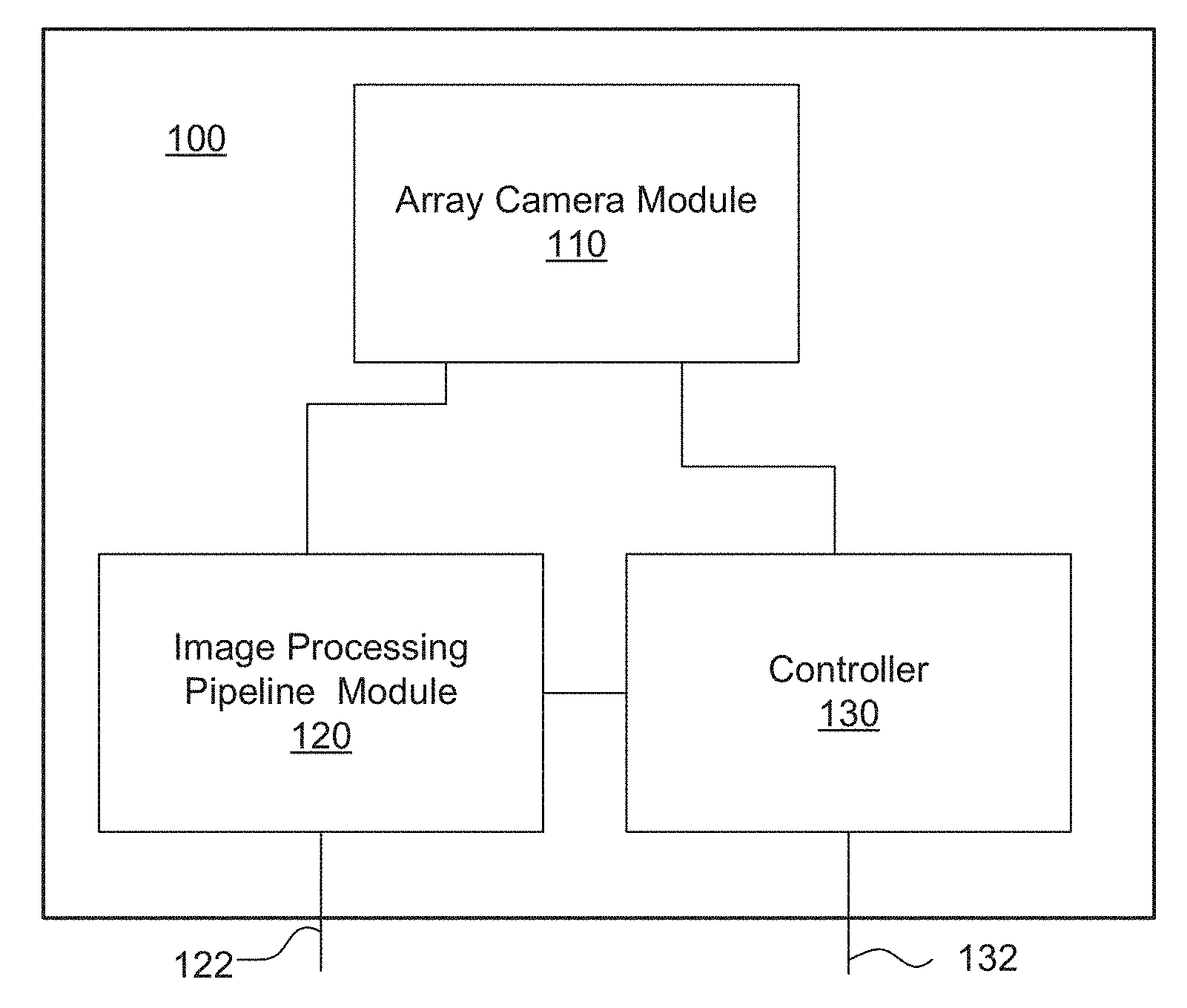
[0021] FIG. 1 conceptually illustrates an array camera.
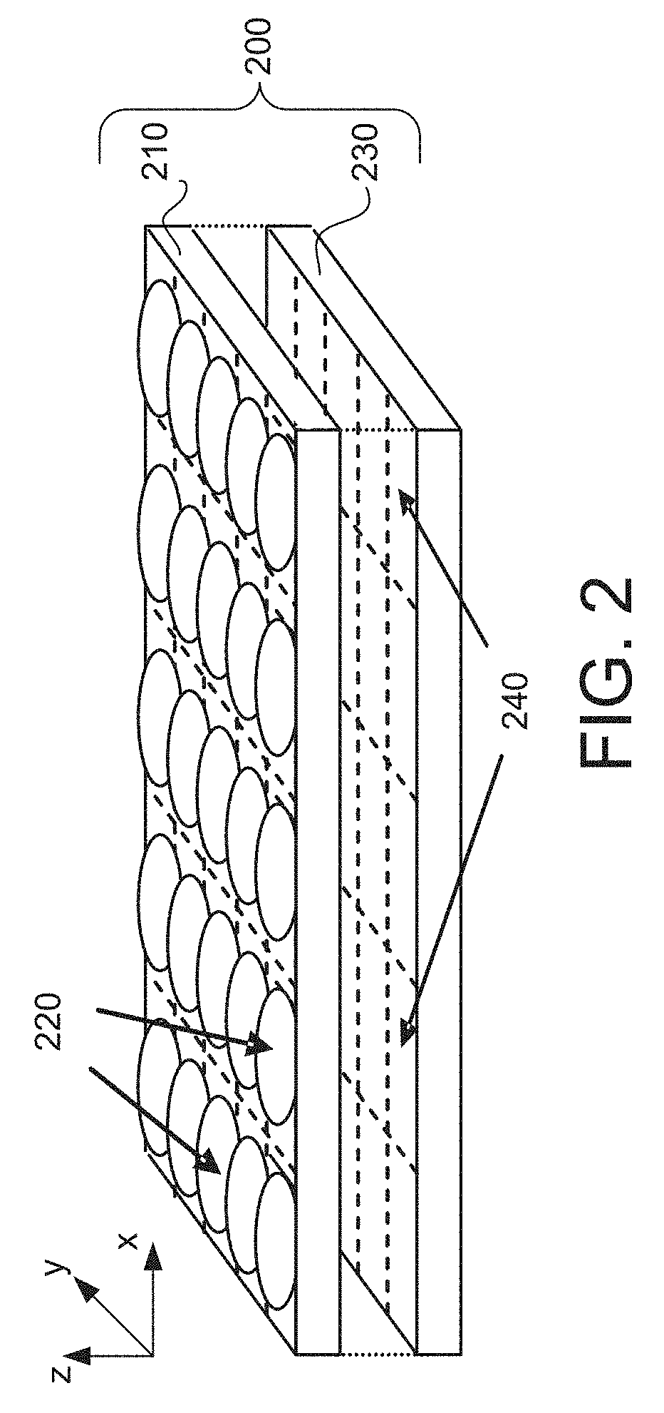
[0022] FIG. 2 illustrates an array camera module.
[0023] FIG. 3 illustrates an array camera module that employs a .pi. filter.
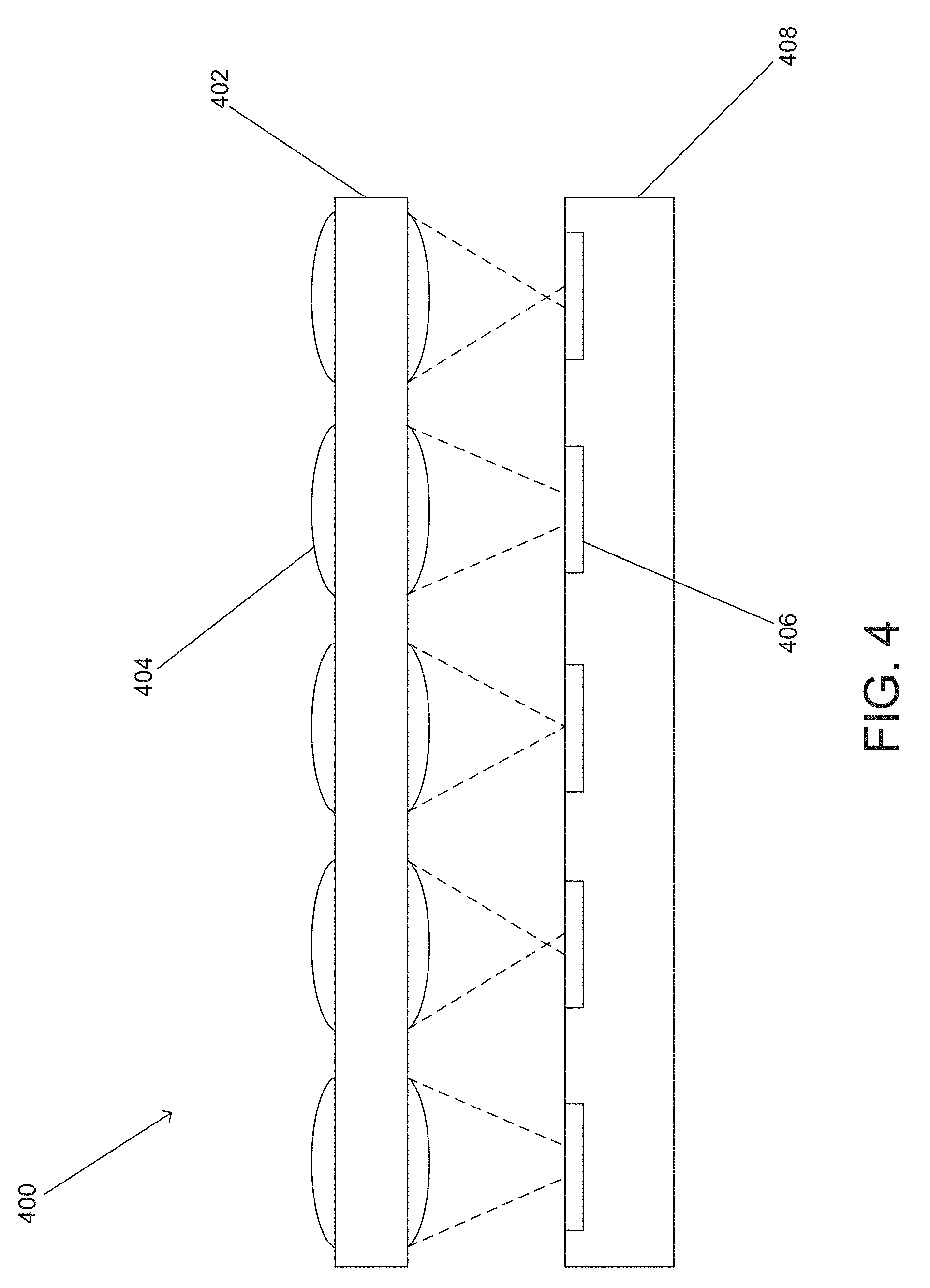
[0024] FIG. 4 conceptually illustrates variations in focal length that can occur during the manufacture of a camera module using a lens stack array and a sensor in accordance with embodiments of the invention.
[0025] FIG. 5 is a flowchart that illustrates a process for actively aligning a lens stack array and a sensor including an array of corresponding focal planes in accordance with an embodiment of the invention.
[0026] FIG. 6 schematically illustrates an initial configuration that may be used to actively align a lens stack array with a sensor in accordance with an embodiment of the invention.
[0027] FIG. 7 illustrates sweeping a lens stack array with respect to a sensor in accordance with an embodiment of the invention.
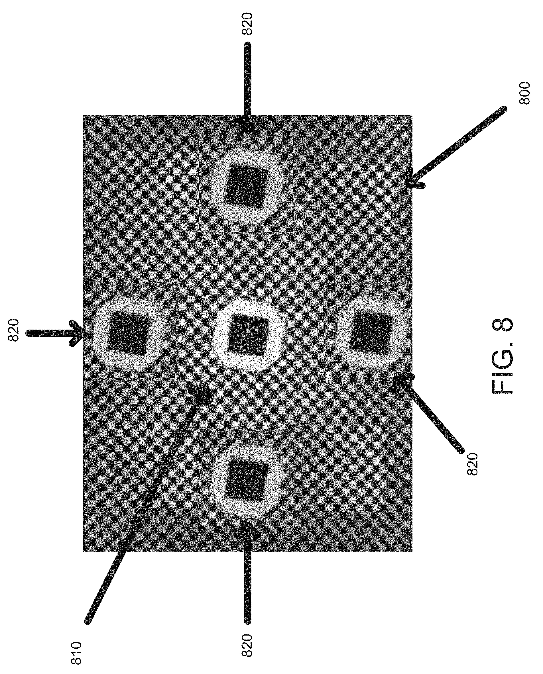
[0028] FIG. 8 illustrates a target that may be used during active alignment in accordance with many embodiments of the invention.
[0029] FIG. 9 is a flowchart that illustrates an active alignment process that uses an iterative computation process to yield an array camera module that is capable of capturing and recording images that have sufficient on-axis and off-axis performance in accordance with an embodiment of the invention.
DETAILED DESCRIPTION
[0030] Turning now to the drawings, systems and methods for actively aligning a lens stack array with an array of focal planes on a monolithic sensor in accordance with embodiments of the invention are illustrated. Processes for constructing array cameras using lens stack arrays are described in U.S. patent application Ser. No. 12/935,504, entitled "Capturing and Processing of Images Using Monolithic Camera Array with Heterogeneous Imagers", Venkataraman et al. The disclosure of U.S. patent application Ser. No. 12/935,504 is incorporated by reference herein in its entirety. The monolithic camera modules illustrated in U.S. patent application Ser. No. 12/935,504 can be constructed from a lens stack array and a sensor including a plurality of focal planes corresponding to the optical channels in the lens stack array. The combination of a lens stack and its corresponding focal plane can be understood to be a `camera module.` Ideally, the lens stack array of an array camera is constructed so that each optical channel has the same focal length. However, the large number of tolerances involved in the manufacture of a lens stack array can result in the different optical channels having varying focal lengths. The combination of all the manufacturing process variations typically results in a deviation of the actual ("first order") lens parameters--such as focal length--from the nominal prescription. As a result, each optical channel can have a different axial optimum image location. And consequently, since the sensor is monolithic, it typically cannot be placed a distance that corresponds with the focal length of each camera within an array camera module. Notably, these manufacturing tolerances may result in different focal lengths even as between lens stack arrays fabricated from the same manufacturing process. Thus, in many embodiments of the invention, a lens stack array is actively aligned with an array of focal planes to form an array camera module that is designed to address the detrimental impact that the variance in focal length within a lens stack array may have.
[0031] In the context of the manufacture of camera systems, the term active alignment typically refers to a process for aligning an optical system (e.g. a lens stack array) with an imaging system (e.g. comprising a monolithic sensor) to achieve a final desirable spatial arrangement by evaluating the efficacy of the configuration as a function of the spatial relationship between the optical system and the imaging system. Typically, this process is implemented by using the configuration to capture and record image data (typically of a known target) in real time as the optical system is moving relative to the imaging system. As the optical system is moved relative to the imaging system, the spatial relationship between the two changes, and the characteristics of the recorded image data also change correspondingly. This recorded image data may then be used to align the optical system relative to the imaging system in a desired manner. For example, active alignment can generally be used to determine a spatial relationship that results in a camera module that is capable of recording images that exceed a threshold image quality.
[0032] A lens stack array may be actively aligned with an array of focal planes in accordance with embodiments of the invention. Importantly, active alignment in this context can be far more intricate and nuanced than it is in the context of conventional, single-lens, cameras. Foremost, because a lens stack array is typically embodied in a single integral housing, the spatial orientation of an individual lens stack (with respect to its corresponding focal plane) cannot be separately varied from that of the other lens stacks--instead, varying the spatial orientation of one lens stack invariably changes the spatial orientation of the others. Consequently, it may not be possible for multiple cameras to be spatially located at their own respective most desirable positions. As a result, active alignment in the context of array cameras may involve computing a final arrangement that, although does not necessarily place each camera at its own optimal position, sufficiently orients the lens stacks of multiple cameras so that the array camera module as a whole achieves a desirable level of performance.
[0033] Additionally, the active alignment of a lens stack array with an array of focal planes typically involves the evaluation of the efficacy of multiple cameras--as opposed to a single camera--at respective varied spatial relationships. In many embodiments, the efficacy of a camera is determined by evaluating the camera's captured and recorded images of a known target at varied spatial relationships. For instance, the Modulation Transfer Function (MTF) score--a numerical score that is indicative of a recorded image's sharpness and thus also focus--may be determined for a given recorded image and used to evaluate a respective camera at a respective spatial orientation. Moreover, the recorded images may be evaluated at different Regions of Interest (ROIs), and in particular at different field heights. For example, an MTF score may be assigned to each ROI within a recorded image. Thus, the corresponding cameras may be evaluated as to each ROI, and this evaluation data may be used to conclude a desirable array camera module configuration.
[0034] In several embodiments, only a subset of all of the cameras in an array camera module is used during the evaluation process. The cameras that define this subset may be predetermined, or they may be computationally determined by considering an initial set of image data captured by some or all of the focal planes.
[0035] Furthermore, unlike in conventional, single-lens, cameras, the active alignment of an array camera module can involve strategically disabling cameras. For example, if the picture quality of a camera when the array camera module is in an estimated final arrangement is below a specified threshold quality, the camera may be disabled. Thus, in many embodiments of the invention, the active alignment process is initially used to estimate a final arrangement for an array camera module, identify cameras that should be disabled on the basis that they do not achieve a threshold quality and disabling them can improve the overall performance of the other cameras in the camera module, and then compute a final arrangement wherein the disabled cameras are excluded from the computation process. Note that this is possible because an array camera includes a plurality of cameras and is still operable if several of the cameras are deactivated. Namely, the array camera may be configured to rely on the remaining active cameras to function, and synthesize an image based on those remaining active cameras. By allowing the array camera software to deactivate certain cameras, higher manufacturing yields can be achieved that can reduce the cost of the completed camera module.
[0036] Array cameras and systems and methods for actively aligning lens stack arrays and sensors to form camera modules for use in array cameras in accordance with embodiments of the invention are discussed further below.
Array Camera Architectures
[0037] FIG. 1 illustrates an array camera architecture disclosed in U.S. application Ser. No. 12/935,504. The array camera 100 includes an array camera module 110, which is connected to an image processing pipeline module 120 and to a controller 130. The image processing pipeline module 120 is hardware, firmware, software, or a combination for processing the images received from the array camera module 110. The image processing pipeline module 120 is capable of processing multiple images captured by multiple focal planes in the camera module and can produce a synthesized higher resolution image. In a number of embodiments, the image processing pipeline module 120 provides the synthesized image data via an output 122.
[0038] The controller 130 is hardware, software, firmware, or a combination thereof for controlling various operational parameters of the array camera module 110. The controller 130 receives inputs 132 from a user or other external components and sends operation signals to control the array camera module 110. The controller can also send information to the image processing pipeline module 120 to assist processing of the images captured by the focal planes in the array camera module 110.
[0039] Although a specific array camera architecture is illustrated in FIG. 1, camera modules constructed using active alignment processes in accordance with embodiments of the invention can be utilized in any of a variety of array camera architectures. Camera modules that can be utilized in array cameras and processes for manufacturing camera modules utilizing active alignment processes in accordance with embodiments of the invention are discussed further below.
Array Camera Modules
[0040] FIG. 2 illustrates an exploded view of an array camera module formed by combining a lens stack array with a monolithic sensor that includes a corresponding array of focal planes as disclosed in U.S. application Ser. No. 12/935,504. The array camera module 200 includes a lens stack array 210 and a sensor 230 that includes an array of focal planes 240. The lens stack array 210 includes an array of lens stacks 220. Each lens stack creates an optical channel that resolves an image on the focal planes 240 on the sensor. Each of the lens stacks may be of a different type. For example, the optical channels may be used to capture images at different portions of the spectrum and the lens stack in each optical channel may be specifically optimized for the portion of the spectrum imaged by the focal plane associated with the optical channel. More specifically, an array camera module may be patterned with ".pi. filter groups." The term .pi. filter groups refers to a pattern of color filters applied to the lens stack array of a camera module and processes for patterning array cameras with .pi. filter groups are described in U.S. Patent Application Ser. No. 61/641,164, entitled "Camera Modules Patterned with .pi. Filter Groups", Venkataraman et al. The disclosure of U.S. Patent Application Ser. No. 61/641,164 is incorporated by reference herein in its entirety. FIG. 3 illustrates a single .pi. filter group, wherein 5 lenses are configured to receive green light, 2 lenses are configured to receive red light, and 2 lenses are configured to receive blue light. The lens stacks may further have one or multiple separate optical elements axially arranged with respect to each other.
[0041] A lens stack array may employ wafer level optics (WLO) technology. WLO is a technology that encompasses a number of processes, including, for example, molding of lens arrays on glass wafers, stacking of those wafers (including wafers having lenses replicated on either side of the substrate) with appropriate spacers, followed by packaging of the optics directly with the imager into a monolithic integrated module.
[0042] The WLO procedure may involve, among other procedures, using a diamond-turned mold to create each plastic lens element on a glass substrate. More specifically, the process chain in WLO generally includes producing a diamond turned lens master (both on an individual and array level), then producing a negative mould for replication of that master (also called a stamp or tool), and then finally forming a polymer replica on a glass substrate, which has been structured with appropriate supporting optical elements, such as, for example, apertures (transparent openings in light blocking material layers), and filters.
[0043] Although the construction of lens stack arrays using specific WLO processes is discussed above, any of a variety of techniques can be used to construct lens stack arrays, for instance those involving precision glass molding, polymer injection molding or wafer level polymer monolithic lens processes. Issues related to variation in back focal length of the lens stacks within lens stack arrays are discussed below.
Back Focal Plane Alignment
[0044] An array camera module is typically intended to be constructed in such a way that each focal plane (i.e. an array of pixels configured to capture an image formed on the focal plane by a corresponding lens stack) is positioned at the focal distance of each lens stack that forms an optical channel. However, manufacturing variations can result in the lens stack in each optical channel varying from its prescription, and in many instances, these variations can result in each lens stack within a lens stack array having a different focal length. For example, parameters that may vary amongst individual lens stacks in a lens stack array because of manufacturing variations include, but are not limited to: the radius of curvature in individual lenses, the conic, higher order aspheric coefficient, refractive index, thickness of the base layer, and/or overall lens height. As one of ordinary skill in the art would appreciate, any number of lens prescriptions may be used to characterize the lens fabrication process, and the respective tolerances may involve departures from these prescriptions in any number of ways, each of which may impact the back focal length. Due to the monolithic nature of the sensor, the spatial relationship of the focal planes (with respect to the lens stacks) cannot be individually customized to accommodate this variability.
[0045] Moreover, in many instances, it is the case that a single manufacturing process is used to fabricate a plurality of lens stack arrays. Consequently, in addition to the aforementioned reasons, the back focal lengths may further vary between lens stacks from different lens stack arrays fabricated from the same process. For instance, variability (within tolerance) in the thickness of the lens substrates and spacers employed in the lens stack, especially those toward the sensor cover glass, may further contribute to the variability in the back focal length. Additionally, variability in the (1) thickness of the sensor cover glass, (2) the bond line thickness between the lens spacer and the sensor cover glass, and (3) any air gaps between the sensor and the cover glass, may further exacerbate the variability in the back focal lengths. Thus, even with constant (nominal) process parameters during the lens stack array fabrication and the lens to sensor attachment process, sample to sample variation may result in defocused camera modules.
[0046] The variations in focal length that can occur in a conventional lens stack array are conceptually illustrated in FIG. 4. The array camera module 400 includes a lens stack array 402 in which lens stacks 404 focus light on the focal planes 406 of sensor 408. As is illustrated, variance between the actually fabricated lens stack and its original prescription can result in the lens stack having a focal length that varies slightly from its prescription and consequently an image distance that does not correspond with the distance between the lens stack array and the sensor. Accordingly, the images formed on the focal planes of the sensor can be out of focus. In addition, other manufacturing tolerances associated with the assembly of the array camera module including (but not limited to) variations in spacer thickness and alignment of the lens stack array relative to the sensor can impact all of the optical channels.
Active Alignment Processes
[0047] In many embodiments, processes for actively aligning a lens stack array with a sensor to construct an array camera module involve reading image data captured by multiple focal planes on the sensor as the lens stack array is moved relative to the sensor. The image data can be utilized to evaluate the resulting image quality at different spatial relationships between the sensor and the lens stack array and the spatial relationship that provides a predetermined threshold level of image quality can be utilized to construct the camera module. A process that actively aligns a lens stack array with a sensor by generally aligning the two, varying their spatial relationship, evaluating the resulting configuration during the variation, and configuring the array camera module using the evaluation data in accordance with an embodiment of the invention is illustrated in FIG. 5.
[0048] A lens stack array is generally aligned (510) with a corresponding sensor that has multiple focal planes. The combination is aligned so that each camera within the configuration is capable of capturing and recording images. The spatial relationship of the lens stack array with respect to the sensor is varied (520). In several embodiments, the variation is achieved by sweeping the lens stack array with respect to the sensor. Sweeping can be understood to mean moving one component (i.e. either the lens stack array or the sensor) in relation to the other over time. Sweeping may be in one degree of freedom or it can be across many degrees of freedom. As can readily be appreciated, the array nature of the camera module means that variations in the x, y, and z-directions, and tip/tilt and rotation of the lens stack array with respect to the sensor can all have significant impact on the imaged data captured by the focal planes on the sensor. Note that in many array cameras, focus and consequently sharpness of the cameras is primarily affected by the z-direction and the tip/tilt of the lens stack array with respect to the sensor, with the tip/tilt principally affecting the performance of the corner cameras. Conversely, in a conventional camera that comprises only a single lens stack, the image quality of the camera is primarily driven by the optical system's `z-position` with respect to the sensor. In many embodiments, the path of the sweep is predetermined.
[0049] The quality of the captured image data is evaluated (530) at the varied spatial relationships. For example, in several embodiments of the invention, the configuration is intermittently evaluated during a sweep of the lens stack array with respect to the sensor. In many embodiments, the configuration is evaluated by evaluating multiple cameras' captured and recorded images of a known target at the varied spatial relationships. In several embodiments, only a subset of the configuration's cameras is used for evaluation purposes. An MTF score may be determined for each recorded image and used to evaluate a respective camera at a respective spatial orientation. The recorded images may also be evaluated at its different ROIs. For example, an MTF score may be assigned to each ROI within a recorded image.
[0050] The array camera module is configured (540) using the information obtained during evaluation. In some embodiments, the configuration involves concluding a spatial relationship between the lens stack array and the sensor that results in the corresponding array camera module being able to capture and record images that exceed a threshold quality. The configuration may also involve disabling cameras that do not surpass a threshold quality. Again, because array camera modules include a plurality of cameras, they can still function even when several of the cameras are disabled. The advantage of being able to disable a camera is that the average performance of the array including the camera may be much lower than the average performance of the remaining cameras when the disabled camera is excluded from consideration in determining the appropriate alignment of the lens stack array and sensor.
[0051] Although a process, and its variants, have been described that actively align a lens stack array with a corresponding array of focal planes, any of a number of different processes may be used to actively align a lens stack array with an array of focal planes in accordance with embodiments of the invention. An initial configuration for an active alignment process in accordance with embodiments of the invention is discussed below.
Initial Configuration for Aligning a Lens Stack Array with an Array of Focal Planes
[0052] Active alignment processes may begin from any number of initial configurations in accordance with embodiments of the invention. An initial configuration for an active alignment process where a device that is capable of orienting a lens stack array is connected to a lens stack array of a corresponding array camera module, a processor is connected to the corresponding sensor, and a target is positioned and illuminated so that the array camera module can capture and record it in accordance with an embodiment of the invention is illustrated in FIG. 6. The array camera module 610 includes a lens stack array 620 and a sensor 630 that has corresponding focal planes. The lens stack array and the sensor are generally aligned so that they are capable of capturing and recording images of the target 640. A device that is capable of spatially orienting the lens stack array 640 is connected to the lens stack array 620, and a processor 660 is connected to the sensor. Thus, the processor 660 is capable of capturing and recording images from the sensor 630, while the orientation of the lens stack array 620 is being varied, and the active alignment process can thereby be implemented. The combination of the device for spatially orienting the lens stack array 650 and the processor 660 can be understood to be an active alignment machine 670.
[0053] In many embodiments, the initial configuration involves generally aligning the lens stack array 620 and the sensor 630 so as to ensure that the lens stack array 620 and the sensor 630 are in sufficient translational and rotational alignment such that each lens stack is generally aligned with its corresponding focal plane. Translational motion here refers to motion of a system (i.e. the lens stack array 620 or the sensor 630) in a direction parallel to its respective surface. Rotation here refers to rotation of a system about the Z-axis (i.e. the axis defining the distance between the sensor and the lens stack array) relative to the other. General alignment may be achieved by, for example, monitoring a central feature on a test chart, and moving either the lens stack array or the sensor in translation (with respect to the other system) such that the central feature is centrally located within the central camera modules; this would indicate that the systems are in sufficient translational alignment. Either system may then be rotated with respect to the other so that the midpoints of each lens stack array and its corresponding focal plane define a line that runs generally parallel to the Z-axis. During this rotational adjustment, the systems may also be readjusted to preserve (or enhance) adequate translational alignment. In this way, each lens stack array may be generally aligned with its corresponding focal plane.
[0054] Although many embodiments of the invention employ the initial configuration illustrated in FIG. 6, many other embodiments employ other initial configurations appropriate to the requirements of specific applications. In accordance with embodiments of the invention, any initial configuration may be implemented that allows the spatial relationship between the lens stack array and the sensor to be varied, and further allows the corresponding array camera module to be evaluated, manipulated, and configured based on an evaluation of it. The varying of spatial relationships between the lens stack array and the sensor in accordance with embodiments of the invention is discussed below.
Varying the Spatial Relationship of the Lens Stack Array with Respect to the Sensor
[0055] The spatial relationship between a lens stack array and a corresponding sensor may be varied in any number of ways. For example, an active alignment process where a lens stack array is swept in a direction substantially normal to the sensor's planar surface in accordance with embodiments of the invention is illustrated in FIG. 7. An array camera module 700 includes a lens stack array 710 and a corresponding sensor 720 with an array of focal planes, and the active alignment process sweeps the lens stack array 710 in a predetermined direction 730 substantially normal to the sensor's surface (the z-direction). Note that sweeping the lens stack array in this fashion systematically varies the focus of each camera--typically cameras will be swept in focus and then out of focus. The array camera module may be evaluated on the varied spatial relationships along this sweep. Active alignment processes in accordance with embodiments of the invention can also include tipping, tilting, and/or rotating the lens stack array with respect to the sensor. In many embodiments, only the distance between the lens stack array and the sensor is varied in a sweep referred to as a "through focus sweep" and all relevant calculations to determine the optimum alignment (including centering as well as focus and tip/tilt) are made from images captured during the through focus sweep using the respective curve fittings and center of gravity calculations, respectively. As can be appreciated, a through focus sweep of a skewed lens stack array already provides information about the optimum tip/tilt of the lens stack array relative to the sensor by the appropriate plane fitting calculations of the peak focus positions or equalized MTF, respectively. These calculations are discussed further below.
[0056] In several embodiments, the manner in which the spatial relationship varies is computationally determined. For example, the manner in which the spatial relationship varies may be determined computationally based upon an initial evaluation of the array camera module. Additionally, the manner in which the spatial relationship varies may change during an active alignment process. For instance, after the lens stack array has been swept in a direction substantially normal to the sensor's planar surface, a processor may compute a different sweeping path that may facilitate a better configuration of the array camera module.
[0057] Although several examples have been described related to how the spatial relationship between the lens stack array and the sensor may be varied, the spatial relationship may also be varied in any number of other ways in accordance with embodiments of the invention. The evaluation of the array camera module at the varied spatial relationships is discussed below.
Evaluating the Array Camera Module
[0058] In numerous embodiments, evaluating the array camera module during the active alignment process involves having multiple cameras capture and record images of a known target, and evaluating these images. The images may be evaluated by assessing their focus, for example. The assessment of the focus may be performed in any number of ways in accordance with embodiments of the invention. For example, in many embodiments, an MTF score may be determined for a given recorded image. Generally speaking, an MTF score is an advantageous metric insofar as MTF scores amongst different cameras can be directly compared with one another. In some embodiments, a recorded image may be given a `focus score` which can similarly be used to evaluate the recorded image. For example, a focus score may be determined by convolving a kernel over contrasting features in an image, where the resulting value is related to the camera's ability to focus. Unlike the MTF score, a focus score may not necessarily be directly comparable to such scores from different cameras; instead a focus score may be more useful in evaluating a single camera.
[0059] The selection of which scoring metric to use may be determined, in part, by the speed in which the scores can be calculated. For instance, if it takes longer to compute an MTF score than to compute a focus score, the focus score may be used in the evaluation. The selection of which scoring metric to use may also be determined, in part, by the accuracy and precision of the score. For instance, if the MTF score is a more precise means for evaluating image quality, then it may be used to evaluate the camera images. Moreover, the active alignment process may utilize several methods of evaluating a recorded image, and these methods may not necessarily be concurrent. For example, an evaluation based on focus scoring may be initially used, whereas an evaluation based on an MTF score may later be used. Additionally, the active alignment process may involve relating the different scoring metrics. For example, focus scoring may be used to evaluate the set of images recorded by an array camera, and MTF scoring may be used to evaluate a representative subset of those images. The MTF scores for the subset may then be normalized to the respective focus scores. And this determined relationship may be used to determine MTF scores for the remaining images.
[0060] Additionally, different regions of recorded images may be evaluated, thereby providing information on a camera's quality as to specific regions. For example, in certain embodiments, images are recorded of a known target that has multiple "Regions of Interest" (ROIs), and the cameras' recorded images of the known target are evaluated with respect to each region of interest. FIG. 8 illustrates a known target used in accordance with many embodiments of the invention. The known target 800 includes a central feature 810 that highlights a central ROI, also known as an "on-axis" ROI. The known target further includes features 820 that highlight "off-axis" ROIs. The target in FIG. 8 is advantageous in so far as the edges of the features are oriented in such a way that the tangential and sagittal components of the MTF score, and thus also the astigmatism, can be directly derived and compared to prior lens test data. Thus, many embodiments utilize the known target illustrated in FIG. 8 by evaluating the quality of each camera with respect to each of the five ROIs.
[0061] The target illustrated in FIG. 8 may also be used in determining a focus score. Specifically, the determination of a focus score in conjunction with this target may involve convolving a kernel over areas of the image with contrasting features for each region of interest (e.g. the checkerboard patterns 840 or the dark slanted square against the light background 850), wherein the resulting value is proportional to the contrast between the features. For example, the following convolution kernel may be employed: [0062] |-1, -1, -1, -1, -1| [0063] |-1, -1, -1, -1, -1| [0064] |-1, -1, 24, -1, -1| [0065] |-1, -1, -1, -1, -1| [0066] |-1, -1, -1, -1, -1|
[0067] This convolution kernel will yield values that are proportional to a camera's ability to resolve contrast. Note that the value will either be positive or negative depending on whether the region being evaluated is transitioning from light to dark or dark to light. However, whether a region of interest is transitioning from light to dark or vice versa is irrelevant to a camera's ability to focus; therefore the absolute value of these values should be obtained. Then, a focus score for each ROI may be obtained by averaging these absolute values for each ROI.
[0068] Although, FIG. 8 illustrates a particular known target that may be used in accordance with embodiments of the invention, many other embodiments utilize other known targets appropriate to the requirements of specific applications. For instance, the off-axis ROIs may be placed in the corners of the target--this allows the performance of the camera to be tested at larger field heights. In the illustrated embodiment, the ROIs have the advantage that the edges of the features are oriented in such a way that the tangential and sagittal components of the MTF and thus also the astigmatism can be directly derived and compared to prior lens test data. Moreover, although specific examples of how a focus score may be generated are provided, any of a variety of techniques can be used to generate a focus score. More generally, the evaluation techniques herein described are merely illustrative. Any techniques for evaluating the efficacy of an array camera module may be incorporated in accordance with embodiments of the invention. Using the evaluation data to configure the array camera module is discussed below.
Configuring the Array Camera Module
[0069] Evaluation data may be used to configure the array camera module in a number of respects. In many embodiments the array camera module is configured to minimize the detrimental impact caused by variance of focal length within a lens stack array. As described above, variance within a lens stack array may be caused by manufacturing process variations including (but not limited to) those that affect the following parameters: the radius of curvature in individual lenses, the conic, higher order aspheric coefficient, refractive index, thickness of the base layer, and/or overall lens height. Additionally, as described above, the following manufacturing variations related to the fabrication of multiple lens stack arrays and camera modules may further exacerbate the variability in back focal lengths: the thickness of the lens substrates and spacers employed in the stack, especially those toward the sensor cover glass, the thickness of the sensor cover glass used, bond line thickness between the lens spacer and the sensor cover glass, and any air gap between the sensor and the sensor cover glass. Thus, many embodiments evaluate the quality of each camera as a function of its spatial relationship to the sensor; thereafter, the information is used to orient the lens stack array with respect to the sensor so that any deterioration in the quality of the array camera due to the variance in focal length within the lens stack array is lessened.
[0070] Several embodiments generate mathematical equations that approximately characterize data related to camera quality as a function of spatial relationship, and use the derived equations to compute a desired spatial relationship that lessens the detrimental impact of variance in focal length. For example, some embodiments generate polynomial equations that approximately model the focal scoring data. Note that because of the nature of optics, each lens will typically have a peak focal value, and therefore polynomial equations are well suited to characterize the data. In many embodiments, the polynomial equations are generated by determining coefficients for predetermined generic polynomial equations (i.e. those with undetermined coefficients), such that the resulting equation approximately characterizes the data relating the camera quality to the spatial relationship. Many embodiments then use these derived equations to compute a best fit plane that characterizes a spatial relationship that reduces the detrimental impact of variance in focal length.
[0071] Notably, the best-fit planes may be computed in any number of ways. For instance, the best-fit plane may be computed to be a plane that includes an approximation of the peak values of the polynomial equations that characterize focal scoring data as a function of the spatial relationship. But, as described above, focal scoring data may not necessarily be directly comparable across different cameras. Therefore, best-fit planes may also be computed by generating equivalent MTF scores, and determining a plane that maximizes the mean MTF score while minimizing its variance. Specifically, the best-fit planes may be computed to determine a plane wherein the MTF scores amongst the different lens stacks are equalized within some specified tolerance. Moreover, any number of balancing algorithms may be employed to effectuate this computation as appropriate to the requirements of a specific application. The determination of these planes may then be used to facilitate the configuration of the array camera module.
[0072] In several embodiments, the configuration process involves orienting the lens stack array with respect to the sensor to form an array camera module that is capable of achieving pictures that have desired characteristics. In some embodiments, the lens stack array is oriented with respect to the sensor so as to achieve an array camera module that is capable of recording images, wherein the quality of the on-axis aspects of the recorded image exceeds a specified threshold criterion. In several embodiments, the lens stack array is actively aligned with respect to the sensor to achieve an array camera module that is capable of recording images, wherein the quality of the off-axis aspects of the recorded image exceeds a specified threshold criterion. Note also that in various embodiments, the configuration process may involve disabling cameras that are above a certain threshold quality so as to avoid biasing the best fit plane determination. In numerous embodiments, the lens stack array is actively aligned with respect to the sensor to achieve an array camera module that is capable of recording images, wherein the quality of both on-axis and off-axis regions of interest exceed respective specified threshold qualities.
[0073] In many embodiments, the configuration process involves disabling cameras that perform above or below a certain defined threshold quality. Again, because an array camera module has many cameras, it is possible for it to maintain functionality even when some of its cameras are non-functional. In several embodiments, cameras are disabled when their quality, as determined by their ability to focus sharply when in a given spatial orientation, is above or below a threshold value. For example, some embodiments determine whether a camera should be disabled by evaluating an MTF score of its respective recorded images. In many embodiments, if the number of disabled cameras exceeds a specified value, then the array camera module is designated unacceptable. In several embodiments, different threshold values can be specified for different types of cameras within the array camera module. For example, in a number of embodiments that employ .pi. filter groups, different threshold values can be specified for the green cameras, the red cameras, and the blue cameras.
[0074] In various embodiments, information obtained during the evaluation aspect of the active alignment process is used to configure the functionality of the each camera. For example, if it is determined that a particular camera has a focal length that makes it better suited to record images of objects that are at a further distance, the array camera module can be configured to rely more heavily on that camera when synthesizing recorded images of objects at further distances.
[0075] The above descriptions regarding configuring an array camera module in accordance with embodiments of the invention is not meant to be exhaustive. Indeed, array camera modules can be configured in any number of ways based on evaluations of the configuration in accordance with embodiments of the invention. Active alignment processes that configure array camera modules so that they are capable of capturing and recording images that have desirable image properties are discussed below.
Active Alignment Processes that Yield Array Camera Modules Capable of Recording Images that have Desirable Characteristics
[0076] Active alignment processes in accordance with embodiments of the invention can use a variety of metrics to evaluate the image data that is captured during the active alignment process. In several embodiments, the active alignment process can optimize image quality in specific regions of the captured images, can optimize image quality in multiple regions of interest and/or can utilize a variety of metrics including (but not limited to) focus scoring and MTF scoring. An active alignment process that uses an iterative computation process to yield an array camera module that is capable of capturing and recording images that have sufficient on-axis and off-axis performance in accordance with an embodiment of the invention is illustrated in FIG. 9.
[0077] The process is initially configured (902) so that a lens stack array and a corresponding sensor are mounted to an active alignment machine in a manner similar to that seen in FIG. 6, so that they are generally operable as an array camera. This may include generally aligning the lens stack array with its corresponding sensor, which itself may include verifying that the lens stack array and the sensor are in sufficient rotational alignment such that each lens stack is generally aligned with its corresponding focal plane, as described above. A known target with an on-axis ROI and off-axis ROIs (similar to that depicted in FIG. 8) is positioned and illuminated so that the array camera module may capture and record its image. The initial configuration may also include deactivating specific cameras in a predetermined fashion so that they do not record images during the alignment process.
[0078] The lens stack array is swept (904) in a direction normal to the sensor's planar surface, in a manner similar to that seen in FIG. 7, and may be swept for a predetermined distance. During the sweep, the active cameras intermittently capture and record (906) images of the known target. The processor evaluates (908) the recorded images and assigns a `focus score` for each region of interest in each recorded image for each camera. Polynomial equations are derived (910) for each region of interest captured by each camera that best characterizes the focus score as a function of the camera's distance from the sensor. In some embodiments, the polynomial equations are derived by calculating coefficients for a given a predetermined generic polynomial equation (i.e. a polynomial equation with undetermined coefficients). The polynomial equations will typically have a peak value.
[0079] An "on-axis best fit plane" is derived (912) using the peak values of the polynomial equations. The on-axis best fit plane, is characterized in that it maximizes the peak values corresponding to the active cameras and/or minimizes the variance in the peak values.
[0080] The lens stack array is then aligned (914) with the computed best fit on-axis plane. Each active camera captures and records (916) an image of the known target. Each recorded image is then evaluated (918) by determining an MTF score for each ROI. Cameras that do not meet a threshold MTF score are disabled (920). For example, any cameras that do not have an MTF score within 20% of the median on-axis MTF score may be disabled, and subsequently excluded from further alignment position calculations. This threshold may of course be configurable. In other embodiments, other criteria are utilized to determine which cameras should be disabled. Moreover, if a specified number of cameras are disabled, the array camera is deemed unacceptable.
[0081] Assuming the camera is not deemed unacceptable, the previously acquired focus scoring data is scaled (922) using the peak focus score and MTF scores. For example, the MTF Score may be scaled in accordance with the following formula:
Scaled Focus Score.sub.z=(Focus Score.sub.z/Peak Focus Score)*MTF Score
[0082] where the z subscript reflects the score at a particular z-position.
[0083] The focus scoring data (absolute values) are exposure/signal-level dependent. Thus different cameras (e.g. blue, green, red cameras) will have different absolute focus score peak values due to their different signal levels. However, MTF is a metric that is invariant to signal level. Thus, MTF enables the curves for focus score to be normalized such that the curve derived from focus score can also be used to compare each camera's peak performance and not only the position at which peak performance occurs. In other embodiments, any of a variety of metrics appropriate to a specific application can be utilized in determining camera peak performance.
[0084] As before, polynomial curves may then be derived (924) that characterize the scaled focus scores. Thus, each active camera will be characterized by polynomial equations that characterize the camera's ability to resolve each respective region of interest. Given these new polynomial equations, a best-fit on axis plane and a best-fit off axis plane are derived (926); in this instance, the best-fit planes are characterized in that they approximately maximize the mean MTF scores while minimizing their variance. A configurable number of planes that are evenly spaced between the two best-fit planes (on-axis and off-axis) are computed (928). Scaled focus scores for each camera at their respective corresponding positions along each of those planes are calculated (930). A best-fit plane determined (932) wherein any deviation toward the best-fit off axis plane causes a gain in the off-axis scaled focus score and a loss in the on-axis scaled score, wherein the ratio of the off-axis score gain to the on-axis score loss falls below a configurable threshold. The lens stack array is then re-aligned (934) with this computed plane.
[0085] The efficacy of the process is verified (936). This may be accomplished by, for example, having each active camera record an image of the known target, determining an MTF score for each ROI within that image, and ensuring that each MTF score surpasses some threshold calculation.
[0086] The processes described may be iterated (938) until a desired configuration is achieved.
[0087] Although a particular process, and its variants, is discussed above, any number of processes may be used to achieve an array camera module that is capable of capturing and recording images that have adequate on-axis and off-axis performance in accordance with embodiments of the invention. Moreover, although the discussed process regards adequately balancing on-axis and off-axis performance of an array camera module, active alignment processes can be tailored to achieve any number of desirable picture characteristics in accordance with embodiments of the invention.
[0088] Although the present invention has been described in certain specific aspects, many additional modifications and variations would be apparent to those skilled in the art. It is therefore to be understood that the present invention may be practiced otherwise than specifically described. Thus, embodiments of the present invention should be considered in all respects as illustrative and not restrictive.
* * * * *
D00000
D00001
D00002
D00003
D00004
D00005
D00006
D00007
D00008
D00009
XML
uspto.report is an independent third-party trademark research tool that is not affiliated, endorsed, or sponsored by the United States Patent and Trademark Office (USPTO) or any other governmental organization. The information provided by uspto.report is based on publicly available data at the time of writing and is intended for informational purposes only.
While we strive to provide accurate and up-to-date information, we do not guarantee the accuracy, completeness, reliability, or suitability of the information displayed on this site. The use of this site is at your own risk. Any reliance you place on such information is therefore strictly at your own risk.
All official trademark data, including owner information, should be verified by visiting the official USPTO website at www.uspto.gov. This site is not intended to replace professional legal advice and should not be used as a substitute for consulting with a legal professional who is knowledgeable about trademark law.