Storage And Transportation Tray With Cooling Means
Spengler; Jan-Peter ; et al.
U.S. patent application number 15/513917 was filed with the patent office on 2019-08-01 for storage and transportation tray with cooling means. The applicant listed for this patent is SANOFI-AVENTIS DEUTSCHLAND GMBH. Invention is credited to Jasmin Groeschke, Sven Hilke, Jan Huesch, Hanno Juhnke, Katrin Kinkel, Jan Moritz Maas, Matthias Scharf, Michael Schrack, Jan-Peter Spengler, Claudio Trankalis.
| Application Number | 20190234681 15/513917 |
| Document ID | / |
| Family ID | 51661926 |
| Filed Date | 2019-08-01 |


| United States Patent Application | 20190234681 |
| Kind Code | A1 |
| Spengler; Jan-Peter ; et al. | August 1, 2019 |
STORAGE AND TRANSPORTATION TRAY WITH COOLING MEANS
Abstract
Embodiments may relate to a storage and transportation tray for a manifold of cartridges filled with a liquid medicament. The tray comprises a planar bottom and at least one side wall at an outer edge of the bottom to form a storage volume with the bottom. The storage volume will accommodate the manifold of cartridges. The storage volume is accessible through an access opening formed by an upper edge of the at least one side wall. At least one cooling member or several cooling members may be thermally coupled with at least one of bottom; side wall and access opening. to keep the cartridges located in the storage volume refrigerated.
| Inventors: | Spengler; Jan-Peter; (Frankfurt am Main, DE) ; Scharf; Matthias; (Frankfurt am Main, DE) ; Groeschke; Jasmin; (Frankfurt am Main, DE) ; Trankalis; Claudio; (Frankfurt am Main, DE) ; Juhnke; Hanno; (Frankfurt am Main, DE) ; Kinkel; Katrin; (Frankfurt am Main, DE) ; Hilke; Sven; (Frankfurt am Main, DE) ; Maas; Jan Moritz; (Frankfurt am Main, DE) ; Schrack; Michael; (Frankfurt am Main, DE) ; Huesch; Jan; (Pliezhausen, DE) | ||||||||||
| Applicant: |
|
||||||||||
|---|---|---|---|---|---|---|---|---|---|---|---|
| Family ID: | 51661926 | ||||||||||
| Appl. No.: | 15/513917 | ||||||||||
| Filed: | September 29, 2015 | ||||||||||
| PCT Filed: | September 29, 2015 | ||||||||||
| PCT NO: | PCT/EP2015/072313 | ||||||||||
| 371 Date: | March 23, 2017 |
| Current U.S. Class: | 1/1 |
| Current CPC Class: | F25D 3/08 20130101; F25D 3/06 20130101; F25D 25/005 20130101 |
| International Class: | F25D 25/00 20060101 F25D025/00; F25D 3/08 20060101 F25D003/08 |
Foreign Application Data
| Date | Code | Application Number |
|---|---|---|
| Oct 2, 2014 | EP | 14187502.1 |
Claims
1-14. (canceled)
15. A storage and transportation tray for a manifold of cartridges filled with a liquid medicament, the storage and transportation tray comprising: a planar bottom and at least one side wall at an outer edge of the bottom to form a storage volume with the bottom to accommodate the manifold of cartridges, wherein the storage volume is accessible through an access opening formed by an upper edge of the at least one side wall, at least one cooling member thermally coupled with at least one of the bottom, the side wall and the access opening to keep the cartridges located in the storage volume refrigerated, wherein at least one of the at least one side wall and the bottom comprises a fastening structure to releasably engage with a corresponding fastening structure of a cooling member filled with a coolant medium.
16. The storage and transportation tray according to claim 15, wherein at least one of the cooling members forms at least one of the at least one side wall and the bottom and comprises a hollow shell filled with a coolant medium.
17. The storage and transportation tray according to claim 15, wherein the cooling member comprises a planar cooling pad to cover the access opening and further comprises at least one cooling lamella extending into the storage volume to thermally couple with at least some of the manifold of cartridges.
18. The storage and transportation tray according to claim 15, wherein the cooling member comprises a cooling line extending along or inside of at least one of the bottom and the at least one side wall.
19. The storage and transportation tray according to claim 18, wherein the cooling line is in flow communication with a feed line extending into at least one of the bottom and the side wall and is further in flow communication with a discharge line extending out of at least one of the bottom and the side wall.
20. The storage and transportation tray according to claim 15, wherein the cooling member comprises a refrigerating machine arranged inside at least one of the bottom, the at least one side wall and the storage volume and which is further coupled with a temperature sensor and a controller to keep the temperature inside the storage volume at a predefined level.
21. The storage and transportation tray according to claim 15, wherein an upper edge of the side wall comprises a first stacking structure and wherein a lower edge of the side wall comprises a second stacking structure mating with the first stacking structure to form a stack of trays.
22. A system comprising: an arrangement of at least two storage and transportation trays, each of the at least two storage and transportation trays comprising a planar bottom and at least one side wall at an outer edge of the bottom to form a storage volume with the bottom to accommodate the manifold of cartridges, wherein the storage volume is accessible through an access opening formed by an upper edge of the at least one side wall, at least one cooling member thermally coupled with at least one of the bottom, the at least one side wall and the access opening to keep the cartridges located in the storage volume refrigerated, wherein the at least one cooling member is arranged at least one of below, above and around the arrangement of storage and transport trays.
23. The system according to claim 22, wherein the at least one cooling member is arranged between adjacently arranged storage and transportation trays.
24. The system according to claim 22, wherein the cooling member is connectable with a cooling supply.
25. The storage and transportation tray according to claim 15, wherein at least one of the at least one side wall and the bottom comprises a fastening structure to releasably engage with a corresponding fastening structure of a cooling member filled with a coolant medium.
26. The storage and transportation tray according to claim 15, wherein the cooling member comprises a refrigerating machine and is further coupled with a temperature sensor and a controller to keep the temperature inside the storage volume at a predefined level.
27. The storage and transportation tray according to claim 15 wherein the cooling member comprises a planar cooling pad to cover the access opening and further comprises at least one cooling lamella extending into the storage volume to thermally couple with at least some of the manifold of cartridges.
28. A cooling system to refrigerate an arrangement of storage and transportation trays, the cooling system comprising: a carriage to carry a support for an arrangement of trays; and at least one cooling member to thermally couple with at least one of the support and the arrangement of trays.
29. The cooling system according to claim 28, wherein the cooling member forms an enclosure to receive the carriage with an arrangement of trays located on the carriage.
30. The cooling system according to claim 28, wherein the cooling member comprises a cooling layer arranged between the support and the carriage or between the support and a lowermost tray, wherein the cooling layer is connectable with a cooling supply.
31. The cooling system according to claim 30, wherein the cooling layer is configured to receive a coolant from the cooling supply that is embedded in the cooling system or is provided on site.
32. The cooling system according to claim 28, wherein the cooling member comprises a liftable and lowerable cooling bell to accommodate the arrangement of trays.
33. The cooling system of claim 28, wherein the cooling system is engagable to at least one of a side wall, access opening, and bottom of a tray of the arrangement of trays.
34. The cooling system of claim 28, wherein the cooling system includes: a refrigeration machine; a temperature sensor; and a controller configured to control a cooling strength of the refrigeration machine based on input from the temperature sensor.
Description
CROSS-REFERENCE TO RELATED APPLICATIONS
[0001] This application is a U.S. national stage application under 35 USC .sctn. 371 of International Application No. PCT/EP2015/072313, filed on Sep. 29, 2015, which claims priority to European Patent Application No. 14187502.1 filed on Oct. 2, 2014, the entire contents of which are incorporated herein by reference.
TECHNICAL FIELD
[0002] The present disclosure relates to the field of storage and transportation trays for a manifold of cartridges filled with a liquid medicament. Additional aspects further relate to an arrangement of at least two storage and transportation trays and further to a cooling system to refrigerate an arrangement of at least two storage and transportation trays as they are commonly used for mass manufacturing of drug delivery devices equipped with such cartridges.
BACKGROUND
[0003] Drug delivery devices for setting and dispensing a single or multiple doses of a liquid medicament are as such well-known in the art. Generally, such devices have substantially a similar purpose as that of an ordinary syringe.
[0004] Drug delivery devices, in particular pen-type injectors have to meet a number of user-specific requirements. For instance, with patient's suffering chronic diseases, such like diabetes, the patient may be physically infirm and may also have impaired vision. Suitable drug delivery devices especially intended for home medication therefore need to be robust in construction and should be easy to use. Furthermore, manipulation and general handling of the device and its components should be intelligible and easy understandable. Moreover, a dose setting as well as a dose dispensing procedure must be easy to operate and has to be unambiguous.
[0005] Typically, such devices comprise a housing or a particular cartridge holder, adapted to receive a cartridge at least partially filled with the medicament to be dispensed. The device further comprises a drive mechanism, usually having a displaceable piston rod which is adapted to operably engage with a piston of the cartridge. By means of the drive mechanism and its piston rod, the piston of the cartridge is displaceable in a distal or dispensing direction and may therefore expel a predefined amount of the medicament via a piercing assembly, which is to be releasably coupled with a distal end section of the housing of the drug delivery device.
[0006] The medicament to be dispensed by the drug delivery device is provided and contained in a multi-dose cartridge. Such cartridges typically comprise a vitreous barrel sealed in distal direction by means of a pierceable seal and being further sealed in proximal direction by the piston. With reusable drug delivery devices an empty cartridge is replaceable by a new one. In contrast to that, drug delivery devices of disposable type are to be entirely discarded when the medicament in the cartridge has been completely dispensed or used-up.
[0007] Disposable drug delivery devices, such like pen injectors are initially equipped with a cartridge filled with a liquid medicament. Typically, the medicament and hence the cartridge requires cooling or refrigerating during storage. Assembling of disposable drug delivery devices and in particular assembling of the cartridge inside the delivery device is fully automated and is implemented in a mass manufacturing process. Manufacturing of a large number of delivery devices within a comparatively short time interval requires a constant supply of a large amount of such cartridges. In the production and assembly environment, the final assembly of the cartridge into the drug delivery device takes place at room temperature. For not affecting the medicament and in order to provide a high quality standard the time interval for which such cartridges are exposed to room temperature should be as short as possible. These demands impose rather sophisticated restrictions and constrictions regarding the supply of cartridges in the mass manufacturing process.
[0008] Typically, cartridges filled with a medicament and to be assembled into a drug delivery device are stored and transported in storage and transportation trays, in which the cartridges are densely packed. Every storage and transportation tray therefore represents a batch of cartridges that has to be supplied in the manufacturing process and hence to an assembly line.
[0009] The batch-wise processing of cartridges may have a further negative influence on the temperature stability of the medicament contained therein during the mass manufacturing process. Cartridges taken last from such a storage and transportation tray might be exposed to room temperature for a longer time than those cartridges that are processed first from such storage and transportation trays.
SUMMARY
[0010] A first aspect the invention relates to a storage and transportation tray for a manifold of cartridges that are filled with a liquid medicament. The storage and transportation tray comprises a planar bottom and at least one sidewall arranged at an outer edge of the bottom to form a storage volume with the bottom. The storage volume is adapted and designed to accommodate the manifold of cartridges, typically in a densely-packed configuration, wherein adjacently located cartridges directly touch in order to exploit the storage volume in a most effective way. The side walls and the bottom form a void space that equals the storage volume which is densely packable by the manifold of cartridges.
[0011] The storage and transportation tray typically comprises numerous sidewalls, e.g. four sidewalls that are arranged in a rectangular fashion so as to form a box-shaped storage and transportation tray. The storage and transportation tray may be of cubic shape. Alternatively, it is conceivable, that the tray only comprises a single sidewall, entirely surrounding the outer circumference or the outer edge of the bottom. A single sidewall may constitute a storage and transportation tray of e.g. cylindrical or oval cross-section.
[0012] In general, the storage volume formed by at least the planar bottom and the sidewall is accessible from the top through an access opening formed by an upper edge of the at least one sidewall. Typically, the sidewall extends substantially perpendicular to the planar bottom. A lower edge of the sidewall is typically connected to the outer edge of the bottom so that the upper edge of the at least one sidewall forms a kind of a free end or free edge, thereby defining the access opening. In typical embodiments the storage and transportation tray is lidless; hence the access opening is not covered by a lid but its storage volume readily accessible from above.
[0013] The storage and transportation tray further comprises at least one cooling member that is thermally coupled with at least one of bottom, sidewall and access opening to keep the cartridges located inside the storage volume refrigerated. The storage and transportation try may also comprise or may be equipped with several cooling members. By providing the storage and transportation tray with at least one cooling member, the critical time interval during which the tray equipped with cartridges can be kept at room temperature can be prolonged. The cooling member may help to keep the cartridges cool and refrigerated even when the storage and transportation tray is exposed to an elevated temperature, such like room temperature. The cooling member can be implemented in many different ways. It may be implemented as a passive cooling member to store thermal, hence cooling energy, e.g. in a refrigerated environment and to absorb thermal energy, e.g. in form of heat, from a heated environment or at room temperature in order to prevent a premature heating of the cartridges and the medicament above a critical temperature, at which the medicament could be affected.
[0014] By means of the at least one cooling member the storage and transportation tray can be kept for a comparatively long time at room temperature, e.g. during assembly of drug delivery devices without running into danger that the medicament stored therein could be affected due to thermal treatment. In this way, a batch of cartridges can be stored and kept for a much longer time interval in the vicinity of an assembly line without running into danger, that the medicament is warmed up to or above a critical temperature.
[0015] In addition, at least one of the bottom and the at least one sidewall comprises a fastening structure to releasably engage or to detachably engage with a corresponding fastening structure of a cooling member, wherein said cooling member is filled with a coolant medium. The cooling member may be provided as a separate thermal pack that can be attached and assembled to the tray. In the same way the thermal pack could be released and disassembled from the tray.
[0016] The separate thermal pack or cooling member can be kept in a refrigerated environment in order to store thermal energy, in particular to store cooling energy. The fastening structures of cooling member and tray mutually mate in such a way, that a rather easy and intuitive assembly and disassembly thereof is provided. Typically, the mutually engaging fastening structures of cooling member and tray may positively or frictionally engage. For this purpose, the mutually corresponding fastening structures may comprise male and female fastening elements, such like protrusions and recesses.
[0017] It may of particular benefit, when the tray's fastening structure is arranged at an outside-facing sidewall portion or at an outside-facing portion of the planar bottom. In this way, the releasable attachment of the cooling member to the tray does not influence and does not decrease the effective storage volume of the storage and transportation tray. The tray's fastening structure may also be arranged at an inside-facing side of the sidewall portion or of the bottom. Then, a thermal coupling between the cooling member or members and the cartridges located in the storage volume of the tray can be improved.
[0018] Moreover, since the cooling member is detachable from the tray it can be cooled down to a much larger degree than the cartridges filled with the liquid medicament. While the cartridges may have to be kept at a temperature of e.g. around 5.degree. C. the cooling member or a manifold of cooling members can be kept at much lower temperatures before they are attached to the tray via the mutually mating fastening structures. In this way, a cooling efficiency of the cooling member can be further enhanced.
[0019] The at least one cooling member that comprises a fastening structure may be of passive or of active type. When implemented as an active cooling member, the cooling member is configured to generate a cooling effect and to lower temperature in its close vicinity. It is then configured to convert electrical or chemical energy into a cooling effect. When implemented as an active cooling member, it may comprise for instance a Peltier element to provide a cooling via the thermoelectric effect. It may also comprise a refrigerating machine that is operable to remove heat from a liquid via a vapor-compression cycle or via an absorption refrigeration cycle.
[0020] According to another embodiment the cooling member or at least one of the cooling members, forms at least one of the at least one sidewall and the bottom and comprises a hollow shell filled with a coolant medium. With this embodiment, at least parts of the tray itself may act as a cooling member. The coolant medium typically comprises a comparatively large heat capacity. The coolant medium contained inside the hollow structure of sidewall and/or bottom may be subject to a cooling when the storage and transportation tray equipped with cartridges is kept in a refrigerated environment before it is provided to the assembly line.
[0021] By having the coolant medium at least inside a sidewall or inside the bottom of the storage and transportation tray, the cartridges arranged inside the storage volume of the tray can be kept at a refrigerated temperature even when the storage and transportation tray should be exposed to room temperature. In this way, the critical time interval during which the cartridges and the medicament are kept out of a refrigerator can be effectively prolonged. In effect, a larger amount of storage and transportation trays can be temporally stored and provided to a manufacturing line at an elevated temperature compared to the critical temperature. In this way, the logistic and material flow for a mass production process can be simplified and optimized without affecting or even by improving a required quality- and/or safety standard.
[0022] According to another embodiment the cooling member or at least one of the cooling members comprises a planar cooling pad to cover the access opening. The cooling member then further comprises at least one cooling lamella extending into the storage volume to thermally couple with at least some of the manifold of cartridges. Typically, the cooling lamella or a series of cooling lamellas are integrally formed or attached to the planar cooling pad. The cooling lamella may extend substantially perpendicular to the plane of the cooling pad. Typically, the cooling lamella extends from a downward-facing surface portion of the cooling pad in order to get in direct mechanical and thermal contact with at least some of the cartridges stored in the storage volume. The cooling pad as well as the cooling lamellas may also be filled with a coolant medium. By means of the cooling pad the access opening of the storage and transportation tray can be effectively closed so as to insulate the storage volume against the environment and to prevent or to counteract ingress of heat or thermal energy into the storage volume via the access opening.
[0023] The cooling lamellas may comprise a structure matching with a densely-packed or predefined configuration of the cartridges when stored and arranged inside the storage and transportation tray. The cooling lamellas may extend from above and in between adjacently-located cartridges.
[0024] The lamellas and/or the cooling pad are typically flexible in order to snuggle to individual cartridges and in order to improve cooling efficiency. The cooling pad as well as the cooling lamellas may comprise a flexible pouch or bag filled with a coolant medium. The coolant medium typically comprises a comparatively large thermal heat capacity or cooling capacity. It is even conceivable, that the coolant medium in general comprises a cold storage medium that is adapted to release cooling energy due to a phase transition. It is in particular conceivable, that the coolant medium undergoes a phase transition, such like a melting and withdraws heat of fusion or latent heat from the environment, thereby providing an effective cooling effect to the surrounding.
[0025] According to another embodiment the cooling member or at least one of the cooling members comprises a cooling line or a cooling tube extending along or inside of at least one of the bottom and the at least one sidewall. The cooling member may comprise a cooling coil extending in a meander-like geometry across or through the bottom and/or the at least one sidewall of the storage and transportation tray. The cooling member may be supplied with a coolant, e.g. via a coolant supply that does not belong to the storage and transportation tray but which is provided in the vicinity of the manufacturing line. With such an embodiment, the storage and transportation tray does not have to be equipped with a coolant medium but can be selectively supplied with a coolant medium on request and as required.
[0026] According to a further embodiment the cooling line is in flow communication with a feed line extending into at least one of the bottom and the sidewall and wherein the cooling line is further in flow communication with a discharge line extending out of at least one of the bottom and the sidewall. Typically, feed line and/or discharge line are connectable to a coolant medium supply. It is particularly conceivable, that the production side is equipped with a coolant supply, such like a cool water port. Then, the cooling line could be connected to the coolant supply via the feed line and a respective coolant, such like cooling water could flow through the cooling line in order to keep at least one of the sidewall and the bottom of the storage and transportation tray at a predefined temperature or in order to prevent an inadmissible heating thereof.
[0027] Typically, the feed line and/or the discharge line comprise standardized couplings or standardized connectors so that the environment of the storage and transportation tray and hence the manufacturing environment is not contaminated with the coolant. A standardized coupling or connector is also beneficial in order to connect and disconnect the mobile storage and transportation tray to an immobile cooling supply installed with the assembly or manufacturing line. It is also conceivable that the connectors of the feed line and the discharge line are mutually connectable. In this way the cooling lines of several adjacently arranged tray can be connected in series or parallel, so that a connection of a series of storage and transportation trays can be easily coupled and connected with an external coolant supply.
[0028] According to another embodiment the cooling member or at least one of the cooling members comprises a refrigerating machine arranged inside at least one of the bottom, the at least one sidewall and the storage volume. The cooling member is further equipped with a temperature sensor and a control, both connected and coupled with the refrigerating machine in order to keep the temperature inside the storage volume at a predefined level. Temperature sensor, control and refrigerating machine may be arranged in a control loop in order to provide a well-defined amount of cooling energy just on demand. The refrigerating machine may be based on various refrigerating principles. It may be based on the Joule-Thomson effect. Like conventional fridges or air conditioning apparatuses it may comprise a coolant circulation by way of which a compressor, a condenser, an expansion valve and an evaporator are coupled.
[0029] Alternatively, it is conceivable, that the refrigerating machine is based on the Peltier effect. Hence, simply by supplying electrical energy to the refrigerating machine, a respective cooling effect could be generated inside the storage and transportation tray.
[0030] Typically, a heat generating portion of the refrigerating machine is thermally coupled to the exterior of the storage and transportation tray while a refrigerating portion of the refrigerating machine is thermally coupled to the storage volume.
[0031] With these embodiments it may be of further benefit, when the access opening is closed by a lid and that the sidewalls, the lid as well as the bottom comprise an insulating material, such like polystyrene or comparable heat insulating materials in order to keep the electrical power consumption of the refrigerating machine at a moderate level.
[0032] According to another embodiment the storage and transportation tray comprises a first stacking structure and a second stacking structure that mutually mate to form a stack of trays, wherein a first tray is arranged on top of a second tray. Typically, an upper edge of the sidewall of the storage and transportation tray comprises the first stacking structure and a lower edge of the sidewall and/or an outer edge of the bottom comprises a second stacking structure. First and second stacking structures mutually mate in order to allow stacking of a multiplicity of equally-shaped storage and transportation trays on top of each other. First and second stacking structures may positively engage. The first stacking structure may comprise male stacking elements while the second stacking structure comprises female stacking elements that are adapted to receive the male stacking elements of the first stacking structure. It is even conceivable, that both first and second stacking structures each comprise male and female stacking elements. By means of mutually mating or mutually corresponding stacking structures, stacking of trays may require a predefined orientation of trays to be stacked on top of each other.
[0033] Another aspect relates to an arrangement of at least two storage and transportation trays as described above. The transportation trays may be arranged next to each other, e.g. on a support surface to form the arrangement of trays. Alternatively, or additionally, the at least two storage and transportation trays may be stacked on top of each other to form the arrangement of storage and transportation trays. With an arrangement of multiple storage and transportation trays the at least one cooling member can be arranged below, above and/or around the arrangement of storage and transport trays. In this way, the cooling member may be adapted and equipped not only to refrigerate and to cool a single but a multiplicity of trays arranged in an arrangement and/or in a stack of trays. In this way, dissipation of cooling energy could be decreased. The overall handling of a large number of cartridges and even of a comparatively large number of trays could be facilitated without running into danger that the medicament is heated or warmed up to a critical temperature during assembly into a drug delivery device.
[0034] According to a further embodiment the at least one cooling member or at least one of the cooling members is arranged between adjacently-arranged storage and transportation trays. In general, any one of the above described cooling members could be arranged between adjacently-located storage and transportation trays. The cooling member could be arranged vertically, between columns or stacks of storage and transportation trays. Alternatively, or additionally the cooling member could also be oriented horizontally, hence between rows of trays so that the cooling member is located between groups of horizontally and adjacently-located trays of a stack of trays.
[0035] With this embodiment, a single storage and transportation tray does not have to be particularly modified. Simply by arranging one or several cooling members between adjacently-arranged storage and transportation trays, the entire stack or the entire arrangement of transportation trays can be effectively cooled and refrigerated.
[0036] According to another embodiment, the cooling member is connectable with a cooling supply. Depending on the specific implementation of the cooling member, the cooling member may either be provided with electrical energy or with a coolant in order to provide an effective cooling of adjacently-located storage and transportation trays.
[0037] Another aspect also relates to a cooling system to refrigerate an arrangement of at least two storage and transportation trays. The cooling system is particularly configured to refrigerate an arrangement of at least two storage and transportation trays as described above. Typically, the transportation trays comprise a planar bottom and at least one sidewall at an outer edge of the bottom to form a storage volume with the bottom, wherein said storage volume is adapted to accommodate the manifold of cartridges. The storage volume is accessible through an access opening formed by an upper edge of the at least one sidewall.
[0038] The cooling system further comprises at least one cooling member to thermally couple with at least one of the support and the arrangement of trays. The cooling system is in particular adapted to provide cooling of an entire stack or of an entire arrangement of a multiplicity of storage and transportation trays. The cooling system is particularly designed to provide cooling and refrigerating of a whole batch of storage and transportation trays, each of which being equipped with a manifold of cartridges filled with a liquid medicament.
[0039] The carriage is a mobile carrier by way of which the arrangement of trays located thereon can be transported in the production environment. The carriage typically comprises a carrier structure in order to carry the support on which the arrangement of trays is stacked or located. The support may comprise a transport pallet and is typically releasably attached and supported by the carriage. The carriage itself comprises wheels or the like in order to provide a smooth transportation of the arrangement of trays, e.g. from a refrigerated environment to the production and assembly line.
[0040] Since the cooling member of the cooling system is adapted to thermally couple with the support and/or with the entire arrangement of trays it provides a very efficient tool for simultaneous cooling and refrigerating of a large number of trays and cartridges located therein. By means of such a particularly large scaled cooling member, individual trays do not have to be separately equipped with a cooling member.
[0041] In this context, the cooling member of the cooling system may be regarded as a global cooling member while cooling members that are individually thermally coupled with at least one of bottom, sidewall and access opening of the storage and transportation tray may be regarded as local cooling members.
[0042] According to a further embodiment the cooling member forms an enclosure to receive the carriage together with an arrangement of trays located thereon. In particular, the cooling member may comprise a kind of a cooling port, hence a surrounding structure comprising sidewalls and a roof portion in between and under which the carriage together with the arrangement of trays is arrangeable. The cooling system could be implemented as an immobile cooling device positioned near the assembly line. It may provide a compartment into which the carriage together with the arrangement of trays could be positioned so that the trays and the cartridges located therein are kept refrigerated as long as possible prior to their final assembly with or in the drug delivery device.
[0043] The cooling member may be further accommodated to receive even more than only one carriage with trays stacked thereon. The cooling member, hence the cooling device typically comprises an access port and/or an exit port through which the carriage with an arrangement of trays thereon can enter a cooling zone provided by the cooling member. Typically, the access and/or exit ports are equipped with at least one or several insulating curtains in order to prevent and to limit dissipation of cooling energy into the environment.
[0044] According to another embodiment the cooling member comprises a cooling layer which is arranged between the support and the carriage or which is arranged between the support and a lowermost tray of the arrangement of trays. The cooling layer is connectable with a cooling supply. The cooling supply may be provided immobile at the manufacturing line and may provide a coolant to flow through the cooling layer. By arranging the cooling layer across the entire support surface of the support and/or of the carriage a cooling and refrigerating of the support and/or of the lowermost tray can be provided. It is of particular benefit, when the arrangement of trays is covered by an insulating sheet providing a cooling atmosphere or cooling environment inside the insulating sheet. In this way also the other storage and transportation trays of the arrangement of trays can be effectively cooled and refrigerated. The cooling supply may be embodied as a cool water supply or as a supply of a coolant featuring a comparatively high thermal heat or cooling capacity. The cooling supply may be installed on the floor of the production environment or assembly line.
[0045] According to another embodiment the cooling member comprises a liftable and lowerable cooling bell to accommodate the arrangement of trays. The cooling bell may either be supplied with a coolant medium or may actively generate a cooling effect. The cooling bell may for instance thermally coupled to an air conditioning system of a building. The cooling bell serves to enclose the entirety of the arrangement of trays. Hence, the cooling bell either comprises a dome-shape structure or a kind of a cubic or rectangular structure to enclose the arrangement of trays. On demand, the cooling bell is liftable into a raised or lifted position so as to provide access to the arrangement of trays. Then, a single or multiple trays can be removed from the arrangement of trays and can be provided and supplied to the manufacturing or assembly line. Thereafter, the cooling bell may be lowered again in order to keep the residual trays in a refrigerated environment.
[0046] The term "drug" or "medicament", as used herein, means a pharmaceutical formulation containing at least one pharmaceutically active compound,
wherein in one embodiment the pharmaceutically active compound has a molecular weight up to 1500 Da and/or is a peptide, a protein, a polysaccharide, a vaccine, a DNA, a RNA, an enzyme, an antibody or a fragment thereof, a hormone or an oligonucleotide, or a mixture of the above-mentioned pharmaceutically active compound, wherein in a further embodiment the pharmaceutically active compound is useful for the treatment and/or prophylaxis of diabetes mellitus or complications associated with diabetes mellitus such as diabetic retinopathy, thromboembolism disorders such as deep vein or pulmonary thromboembolism, acute coronary syndrome (ACS), angina, myocardial infarction, cancer, macular degeneration, inflammation, hay fever, atherosclerosis and/or rheumatoid arthritis, wherein in a further embodiment the pharmaceutically active compound comprises at least one peptide for the treatment and/or prophylaxis of diabetes mellitus or complications associated with diabetes mellitus such as diabetic retinopathy, wherein in a further embodiment the pharmaceutically active compound comprises at least one human insulin or a human insulin analogue or derivative, glucagon-like peptide (GLP-1) or an analogue or derivative thereof, or exendin-3 or exendin-4 or an analogue or derivative of exendin-3 or exendin-4.
[0047] Insulin analogues are for example Gly(A21), Arg(B31), Arg(B32) human insulin; Lys(B3), Glu(B29) human insulin; Lys(B28), Pro(B29) human insulin; Asp(B28) human insulin; human insulin, wherein proline in position B28 is replaced by Asp, Lys, Leu, Val or Ala and wherein in position B29 Lys may be replaced by Pro; Ala(B26) human insulin; Des(B28-B30) human insulin; Des(B27) human insulin and Des(B30) human insulin.
[0048] Insulin derivates are for example B29-N-myristoyl-des(B30) human insulin; B29-N-palmitoyl-des(B30) human insulin; B29-N-myristoyl human insulin; B29-N-palmitoyl human insulin; B28-N-myristoyl LysB28ProB29 human insulin; B28-N-palmitoyl-LysB28ProB29 human insulin; B30-N-myristoyl-ThrB29LysB30 human insulin; B30-N-palmitoyl-ThrB29LysB30 human insulin; B29-N--(N-palmitoyl-Y-glutamyl)-des(B30) human insulin; B29-N--(N-lithocholyl-Y-glutamyl)-des(B30) human insulin; B29-N-(.omega.-carboxyheptadecanoyl)-des(B30) human insulin and B29-N-(.omega.-carboxyheptadecanoyl) human insulin.
[0049] Exendin-4 for example means Exendin-4(1-39), a peptide of the sequence H-His-Gly-Glu-Gly-Thr-Phe-Thr-Ser-Asp-Leu-Ser-Lys-Gln-Met-Glu-Gl- u-Glu-Ala-Val-Arg-Leu-Phe-11e-Glu-Trp-Leu-Lys-Asn-Gly-Gly-Pro-Ser-Ser-Gly-- Ala-Pro-Pro-Pro-Ser-NH2.
[0050] Exendin-4 derivatives are for example selected from the following list of compounds:
H-(Lys)4-des Pro36, des Pro37 Exendin-4(1-39)-NH2,
H-(Lys)5-des Pro36, des Pro37 Exendin-4(1-39)-NH2,
des Pro36 Exendin-4(1-39),
des Pro36 [Asp28] Exendin-4(1-39),
des Pro36 [IsoAsp28] Exendin-4(1-39),
des Pro36 [Met(O)14, Asp28] Exendin-4(1-39),
des Pro36 [Met(O)14, IsoAsp28] Exendin-4(1-39),
des Pro36 [Trp(O2)25, Asp28] Exendin-4(1-39),
des Pro36 [Trp(O2)25, IsoAsp28] Exendin-4(1-39),
des Pro36 [Met(O)14 Trp(O2)25, Asp28] Exendin-4(1-39),
des Pro36 [Met(O)14 Trp(O2)25, IsoAsp28] Exendin-4(1-39); or
[0051] des Pro36 [Asp28] Exendin-4(1-39), [0052] des Pro36 [IsoAsp28] Exendin-4(1-39), [0053] des Pro36 [Met(O)14, Asp28] Exendin-4(1-39), [0054] des Pro36 [Met(O)14, IsoAsp28] Exendin-4(1-39), [0055] des Pro36 [Trp(O2)25, Asp28] Exendin-4(1-39), [0056] des Pro36 [Trp(O2)25, IsoAsp28] Exendin-4(1-39), [0057] des Pro36 [Met(O)14 Trp(O2)25, Asp28] Exendin-4(1-39), [0058] des Pro36 [Met(O)14 Trp(O2)25, IsoAsp28] Exendin-4(1-39), [0059] wherein the group -Lys6-NH2 may be bound to the C-terminus of the Exendin-4 derivative; [0060] or an Exendin-4 derivative of the sequence [0061] des Pro36 Exendin-4(1-39)-Lys6-NH2 (AVE0010), [0062] H-(Lys)6-des Pro36 [Asp28] Exendin-4(1-39)-Lys6-NH2, [0063] des Asp28 Pro36, Pro37, Pro38Exendin-4(1-39)-NH2, [0064] H-(Lys)6-des Pro36, Pro38 [Asp28] Exendin-4(1-39)-NH2, [0065] H-Asn-(Glu)5des Pro36, Pro37, Pro38 [Asp28] Exendin-4(1-39)-NH2, [0066] des Pro36, Pro37, Pro38 [Asp28] Exendin-4(1-39)-(Lys)6-NH2, [0067] H-(Lys)6-des Pro36, Pro37, Pro38 [Asp28] Exendin-4(1-39)-(Lys)6-NH2, [0068] H-Asn-(Glu)5-des Pro36, Pro37, Pro38 [Asp28] Exendin-4(1-39)-(Lys)6-NH2, [0069] H-(Lys)6-des Pro36 [Trp(O2)25, Asp28] Exendin-4(1-39)-Lys6-NH2, [0070] H-des Asp28 Pro36, Pro37, Pro38 [Trp(O2)25] Exendin-4(1-39)-NH2, [0071] H-(Lys)6-des Pro36, Pro37, Pro38 [Trp(O2)25, Asp28] Exendin-4(1-39)-NH2, [0072] H-Asn-(Glu)5-des Pro36, Pro37, Pro38 [Trp(O2)25, Asp28] Exendin-4(1-39)-NH2, [0073] des Pro36, Pro37, Pro38 [Trp(O2)25, Asp28] Exendin-4(1-39)-(Lys)6-NH2, [0074] H-(Lys)6-des Pro36, Pro37, Pro38 [Trp(O2)25, Asp28] Exendin-4(1-39)-(Lys)6-NH2, [0075] H-Asn-(Glu)5-des Pro36, Pro37, Pro38 [Trp(O2)25, Asp28] Exendin-4(1-39)-(Lys)6-NH2, [0076] H-(Lys)6-des Pro36 [Met(O)14, Asp28] Exendin-4(1-39)-Lys6-NH2, [0077] des Met(O)14 Asp28 Pro36, Pro37, Pro38 Exendin-4(1-39)-NH2, [0078] H-(Lys)6-des Pro36, Pro37, Pro38 [Met(O)14, Asp28] Exendin-4(1-39)-NH2, [0079] H-Asn-(Glu)5-des Pro36, Pro37, Pro38 [Met(O)14, Asp28] Exendin-4(1-39)-NH2, [0080] des Pro36, Pro37, Pro38 [Met(O)14, Asp28] Exendin-4(1-39)-(Lys)6-NH2, [0081] H-(Lys)6-des Pro36, Pro37, Pro38 [Met(O)14, Asp28] Exendin-4(1-39)-(Lys)6-NH2, [0082] H-Asn-(Glu)5 des Pro36, Pro37, Pro38 [Met(O)14, Asp28] Exendin-4(1-39)-(Lys)6-NH2, [0083] H-Lys6-des Pro36 [Met(O)14, Trp(O2)25, Asp28] Exendin-4(1-39)-Lys6-NH2, [0084] H-des Asp28 Pro36, Pro37, Pro38 [Met(O)14, Trp(O2)25] Exendin-4(1-39)-NH2, [0085] H-(Lys)6-des Pro36, Pro37, Pro38 [Met(O)14, Asp28] Exendin-4(1-39)-NH2, [0086] H-Asn-(Glu)5-des Pro36, Pro37, Pro38 [Met(O)14, Trp(O2)25, Asp28] Exendin-4(1-39)-NH2, [0087] des Pro36, Pro37, Pro38 [Met(O)14, Trp(O2)25, Asp28] Exendin-4(1-39)-(Lys)6-NH2, [0088] H-(Lys)6-des Pro36, Pro37, Pro38 [Met(O)14, Trp(O2)25, Asp28] Exendin-4(S1-39)-(Lys)6-NH2, [0089] H-Asn-(Glu)5-des Pro36, Pro37, Pro38 [Met(O)14, Trp(O2)25, Asp28] Exendin-4(1-39)-(Lys)6-NH2; [0090] or a pharmaceutically acceptable salt or solvate of any one of the afore-mentioned Exendin-4 derivative.
[0091] Hormones are for example hypophysis hormones or hypothalamus hormones or regulatory active peptides and their antagonists as listed in Rote Liste, ed. 2008, Chapter 50, such as Gonadotropine (Follitropin, Lutropin, Choriongonadotropin, Menotropin), Somatropine (Somatropin), Desmopressin, Terlipressin, Gonadorelin, Triptorelin, Leuprorelin, Buserelin, Nafarelin, Goserelin.
[0092] A polysaccharide is for example a glucosaminoglycane, a hyaluronic acid, a heparin, a low molecular weight heparin or an ultra-low molecular weight heparin or a derivative thereof, or a sulphated, e.g. a poly-sulphated form of the above-mentioned polysaccharides, and/or a pharmaceutically acceptable salt thereof. An example of a pharmaceutically acceptable salt of a poly-sulphated low molecular weight heparin is enoxaparin sodium.
[0093] Antibodies are globular plasma proteins (.about.150 kDa) that are also known as immunoglobulins which share a basic structure. As they have sugar chains added to amino acid residues, they are glycoproteins. The basic functional unit of each antibody is an immunoglobulin (Ig) monomer (containing only one Ig unit); secreted antibodies can also be dimeric with two Ig units as with IgA, tetrameric with four Ig units like teleost fish IgM, or pentameric with five Ig units, like mammalian IgM.
[0094] The Ig monomer is a "Y"-shaped molecule that consists of four polypeptide chains; two identical heavy chains and two identical light chains connected by disulfide bonds between cysteine residues. Each heavy chain is about 440 amino acids long; each light chain is about 220 amino acids long. Heavy and light chains each contain intrachain disulfide bonds which stabilize their folding. Each chain is composed of structural domains called Ig domains. These domains contain about 70-110 amino acids and are classified into different categories (for example, variable or V, and constant or C) according to their size and function. They have a characteristic immunoglobulin fold in which two 1 sheets create a "sandwich" shape, held together by interactions between conserved cysteines and other charged amino acids.
[0095] There are five types of mammalian Ig heavy chain denoted by .alpha., .delta., .epsilon., .gamma., and .mu.. The type of heavy chain present defines the isotype of antibody; these chains are found in IgA, IgD, IgE, IgG, and IgM antibodies, respectively.
[0096] Distinct heavy chains differ in size and composition; .alpha. and .gamma. contain approximately 450 amino acids and .delta. approximately 500 amino acids, while .mu. and .epsilon. have approximately 550 amino acids. Each heavy chain has two regions, the constant region (CH) and the variable region (VH). In one species, the constant region is essentially identical in all antibodies of the same isotype, but differs in antibodies of different isotypes. Heavy chains .gamma., .alpha. and .delta. have a constant region composed of three tandem Ig domains, and a hinge region for added flexibility; heavy chains .mu. and .epsilon. have a constant region composed of four immunoglobulin domains. The variable region of the heavy chain differs in antibodies produced by different B cells, but is the same for all antibodies produced by a single B cell or B cell clone. The variable region of each heavy chain is approximately 110 amino acids long and is composed of a single Ig domain.
[0097] In mammals, there are two types of immunoglobulin light chain denoted by .lamda. and .kappa.. A light chain has two successive domains: one constant domain (CL) and one variable domain (VL). The approximate length of a light chain is 211 to 217 amino acids. Each antibody contains two light chains that are always identical; only one type of light chain, .kappa. or .lamda., is present per antibody in mammals.
[0098] Although the general structure of all antibodies is very similar, the unique property of a given antibody is determined by the variable (V) regions, as detailed above. More specifically, variable loops, three on the light (VL) and three on the heavy (VH) chain, are responsible for binding to the antigen, i.e. for its antigen specificity. These loops are referred to as the Complementarity Determining Regions (CDRs). Because CDRs from both VH and VL domains contribute to the antigen-binding site, it is the combination of the heavy and the light chains, and not either alone, that determines the final antigen specificity.
[0099] An "antibody fragment" contains at least one antigen binding fragment as defined above, and exhibits essentially the same function and specificity as the complete antibody of which the fragment is derived from. Limited proteolytic digestion with papain cleaves the Ig prototype into three fragments. Two identical amino terminal fragments, each containing one entire L chain and about half an H chain, are the antigen binding fragments (Fab). The third fragment, similar in size but containing the carboxyl terminal half of both heavy chains with their interchain disulfide bond, is the crystalizable fragment (Fc). The Fc contains carbohydrates, complement-binding, and FcR-binding sites. Limited pepsin digestion yields a single F(ab').sub.2 fragment containing both Fab pieces and the hinge region, including the H--H interchain disulfide bond. F(ab').sub.2 is divalent for antigen binding. The disulfide bond of F(ab').sub.2 may be cleaved in order to obtain Fab'. Moreover, the variable regions of the heavy and light chains can be fused together to form a single chain variable fragment (scFv).
[0100] Pharmaceutically acceptable salts are for example acid addition salts and basic salts. Acid addition salts are e.g. HCl or HBr salts. Basic salts are e.g. salts having a cation selected from alkali or alkaline, e.g. Na+, or K+, or Ca2+, or an ammonium ion N+(R1)(R2)(R3)(R4), wherein R1 to R4 independently of each other mean: hydrogen, an optionally substituted C1-C6-alkyl group, an optionally substituted C2-C6-alkenyl group, an optionally substituted C6-C10-aryl group, or an optionally substituted C6-C10-heteroaryl group. Further examples of pharmaceutically acceptable salts are described in "Remington's Pharmaceutical Sciences" 17. ed. Alfonso R. Gennaro (Ed.), Mark Publishing Company, Easton, Pa., U.S.A., 1985 and in Encyclopaedia of Pharmaceutical Technology.
[0101] Pharmaceutically acceptable solvates are for example hydrates.
[0102] Some embodiments may provide an improved storage and transportation tray for a manifold of cartridges filled with a liquid medicament by way of which a risk of a critical exposure to room temperature can be decreased. As a result of the improved storage and transportation tray, the time interval during which the tray may be exposed to room temperature should be extended compared to conventional storage and transportation tray solutions. Consequently, certain aspects may facilitate the handling of cartridges in a mass manufacturing process and to simplify the product flow in such processes while fulfilling the demands in respect of cooling or refrigerating of the cartridges.
[0103] Further, it is to be noted, that any reference numerals used in the appended claims are not to be construed as limiting the scope of the invention.
BRIEF DESCRIPTION OF THE DRAWINGS
[0104] In the following, various embodiments will be described in detail by making reference to the drawings, in which:
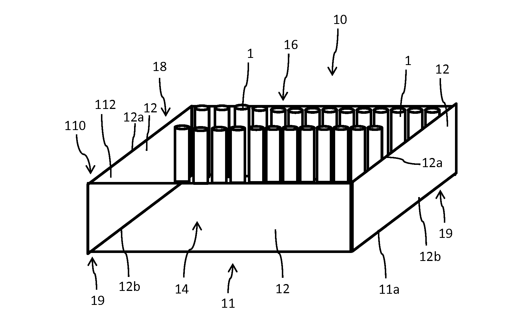
[0105] FIG. 1 schematically shows a storage and transportation tray for a manifold of cartridges,
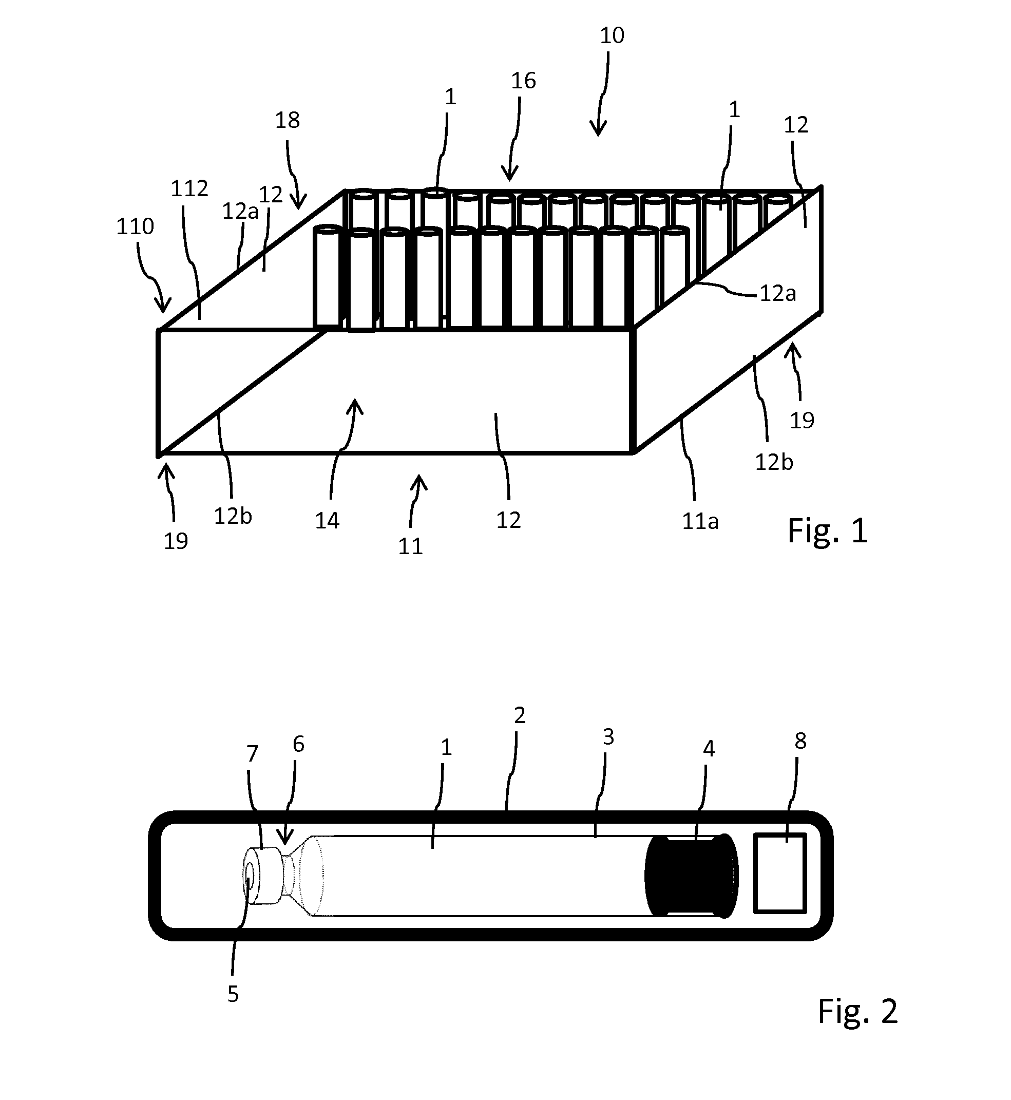
[0106] FIG. 2 schematically illustrates a cartridge assembled in a drug delivery device, such like an injection-pen,
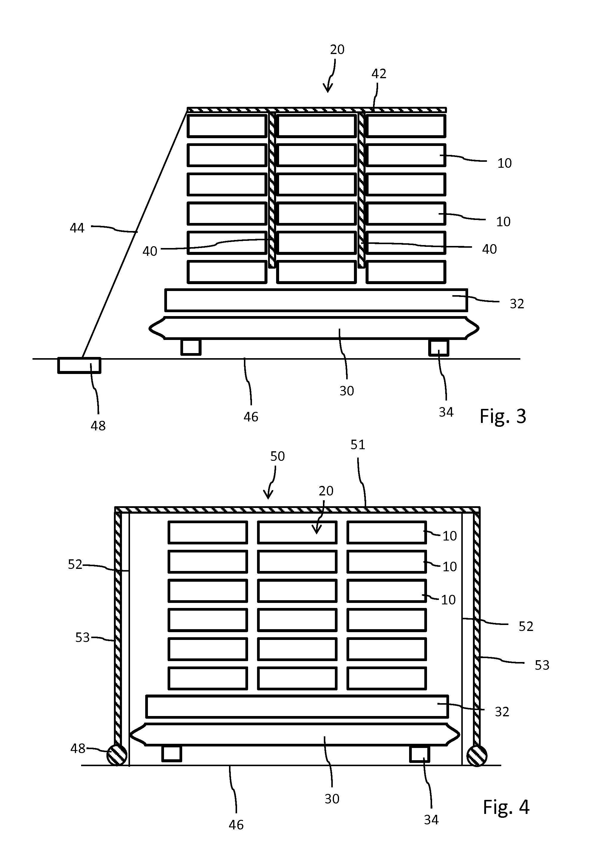
[0107] FIG. 3 shows an arrangement of trays equipped and thermally coupled with a cooling member,
[0108] FIG. 4 schematically shows a cooling system with a cooling member at least partially enclosing the arrangement of trays,
[0109] FIG. 5 shows a different embodiment of the cooling system with a cooling layer arranged between a support and a carriage,
[0110] FIG. 6 shows a further embodiment of the cooling system, wherein the cooling member comprises a liftable cooling bell,
[0111] FIG. 7 schematically shows a storage and transportation tray with a cooling line extending along or inside the sidewalls of the storage and transportation tray,
[0112] FIG. 8 is illustrative of a storage and transportation tray comprising a refrigerating machine,
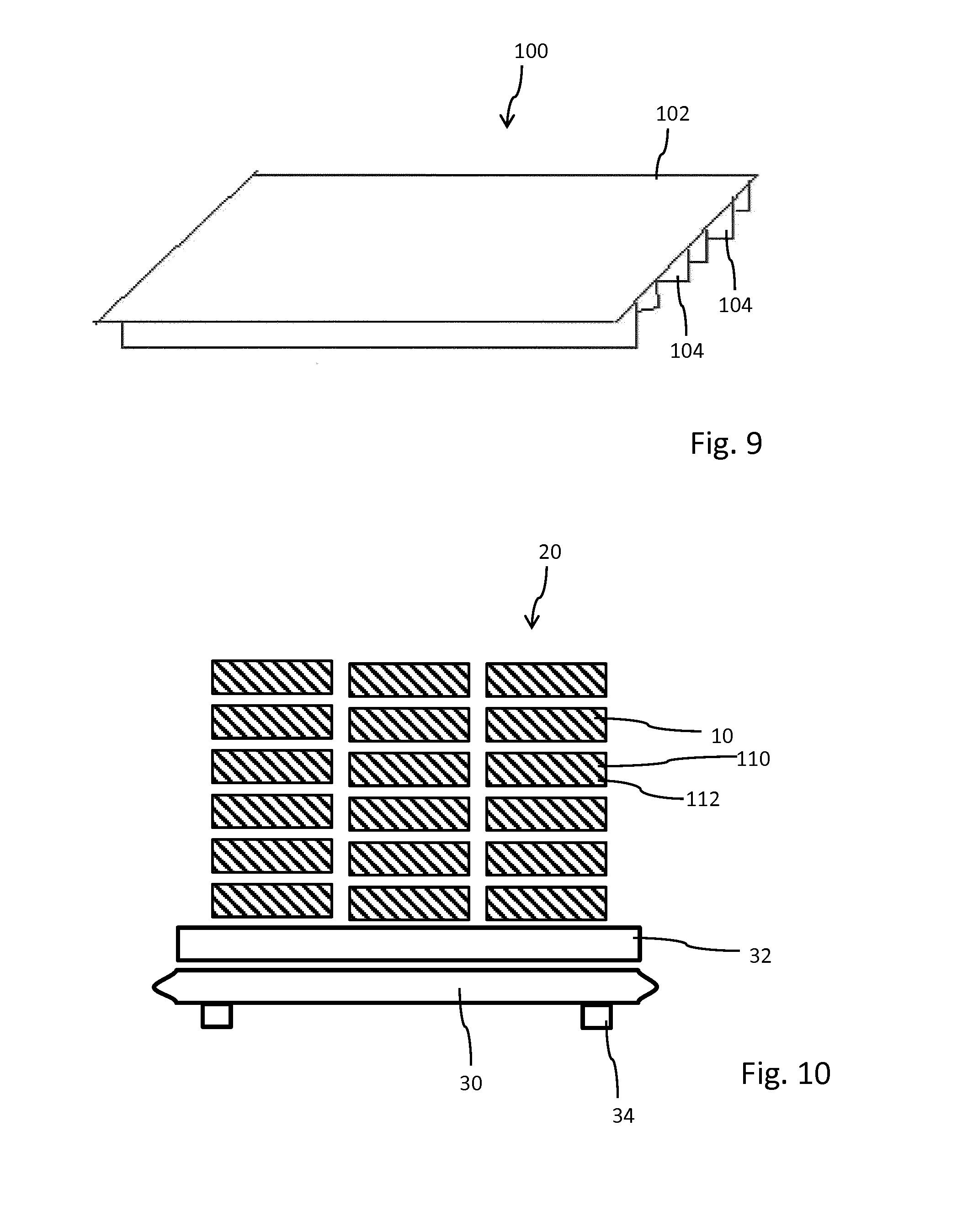
[0113] FIG. 9 schematically shows a planar cooling pad with several cooling lamellas to cover the access opening of the storage and transportation tray,
[0114] FIG. 10 shows a stack or an arrangement of storage and transportation trays, each of which comprising a cooling member,
[0115] FIG. 11 schematically illustrates a storage and transportation tray with a fastening structure to releasably connect with a cooling member filled with a coolant medium and
[0116] FIG. 12 schematically depicts the storage and transportation tray according to FIG. 11 with the cooling member attached to an outside-facing portion of its sidewall.
DETAILED DESCRIPTION
[0117] FIG. 2 shows a rather schematic representation of a drug delivery device 2 equipped with a cartridge 1 that is filled with a medicament. The cartridge 1 typically comprises a vitreous barrel 3, which in proximal direction, hence to the right in FIG. 2, is sealed by a plunger or piston 4 of elastomeric material. Its opposite distal end is sealed by a pierceable septum 5 which is kept in position at a socket or neck portion 6 if the barrel 3 by means of a crimp cap 7. The drug delivery device 2 typically comprises a housing 2 to accommodate the cartridge 1 and to accommodate a drive mechanism 8 by way of which the piston 4 is displaceable in distal direction, hence towards the distal septum 5 for expelling of a dose of the medicament from the interior of the barrel 3. The septum 5 is typically pierced by a double-tipped injection needle which is releasably attachable to the drug delivery device 2.
[0118] The drug delivery device 2 is typically of disposable type. After consumption of the medicament and/or after emptying of the cartridge 1 the entire device 2 is intended to be discarded. With disposable drug delivery devices 2, the cartridge 1 has to be assembled inside the drug delivery device 2 during the process of assembly of the drug delivery device 2. Since assembly and manufacturing of such drug delivery devices 2 is automated to a large degree in a mass manufacturing process a rather large amount of cartridges 1 has to be provided to a respective assembly line. In order to supply the production line with a batch of cartridges 1 storage and transportation trays 10, as illustrated in FIG. 1 are used.
[0119] The tray 10 comprises a planar bottom 11 and four sidewalls 12 or respective sidewall sections. The sidewalls 12 are attached or integrally formed with the planar bottom 10 at the outer edge 11a of the bottom 11. Typically, a lower edge 12b of the sidewall 12 is located adjacent or is connected with the outer edge 11a of the planar bottom 11. Hence, with a rectangular or quadratic-shaped planar bottom 11 and with four sidewalls 12 of equal height, a box-shaped storage and transportation tray 10 is provided. The storage and transportation tray 10 is typically lidless and comprises an access opening 16 that is confined by the upper edges 12a of the sidewalls 12. The sidewalls 12 and the planar bottom 11 form a storage volume 14 in which a manifold of identical cartridges 1 can be accommodated and arranged in a densely-packed configuration. Typically, the cylindrically-shaped cartridges are arranged upright on the bottom 11. They might be arranged to form a densely packed hexagonal structure so as to maximize the transport capacity of the storage and transportation trays 10.
[0120] As it is further illustrated in FIG. 1, the storage tray 10 comprises a first stacking structure 18 on top or at the upper edge 12a of the sidewalls 12 and further has a second stacking structure 19 at a lower edge 12b of the sidewall 12 or at the outer edge 11a of the bottom 11. First and second stacking structures 18, 19 mutually correspond and cooperate to form a stack of storage trays 10 arranged on top of each other. For instance, one of the stacking structures 18, 19 may comprise male stacking elements, such like pins while the other of the stacking structures 18, 19 comprises female stacking elements, such like depressions or recesses to accommodate and to engage with the male stacking elements.
[0121] As it is further indicated in FIG. 1, the tray 10 comprises at least one cooling member 110, which is integrated into at least one of the sidewalls 12. Here, at least one of the sidewall 12 comprises a hollow shell 112 filled with a coolant medium. In other embodiments as shown in FIGS. 3 to 9 and in FIGS. 11 to 12 the cooling members 40, 42, 50, 60, 70, 80, 90, 100 are implemented in a different way but the trays 10 comprise the general structure of sidewalls 12 and bottom 11 as it is described in detail with respect to FIG. 1.
[0122] In the various embodiments according to FIGS. 3-12 the storage and transportation tray 10 as shown in FIG. 1 is equipped with at least one cooling member 40, 42, 50, 60, 70, 80, 90, 100, 110, 120 in order to refrigerate and/or to keep the cartridges 1 located inside the storage volume 14 below a predefined temperature level when located near or at the assembly line at room temperature.
[0123] As it is indicated in FIG. 10 a stack and an arrangement of storage and transportation trays 10, each of which accommodating a manifold of cartridges 1, each and every storage and transportation tray 10 is provided with a separate and individual cooling member 110. As indicated in FIG. 10 at least a sidewall 12 of the storage and transportation trays 10 comprises a hollow shell 112 filled with a coolant medium. In this way, the sidewall 12 of each tray 10 comprises and provides a cooling reservoir that helps to keep the storage volume 14 and the cartridges 1 located therein below a predefined critical temperature in regard to the medicament. The coolant medium contained in the hollow shell 112 of the at least one of sidewall 12 and bottom 11 may be kept together with the cartridges 1 in a cooling or refrigerated environment. When taken out of the refrigerator the cooling capacity of the coolant medium allows to extend a critical time interval until the critical temperature has been reached when the storage and transportation tray is kept at room temperature and/or in a non-refrigerated environment.
[0124] In FIGS. 11 and 12 another embodiment is shown, wherein the cooling member 120 comprises a fastening structure 116 to mate with a corresponding fastening structure 118 of the sidewall 12 of the storage and transportation tray. The cooling member 120 may comprise a kind of a cool pack 121 that is e.g. filled with a coolant medium, that may even be cooled below the refrigerated temperature of the cartridges. By means of the mutually corresponding fastening structures 116, 118, the cooling member 120 can be separately cooled to a different and lower temperature level compared to the cartridges 1. When the storage and transportation tray is removed from a refrigerator, the cooling members 120 can be manually or automatically attached to the sidewall 12 in order to provide a cooling effect to the cartridges 1 located therein. The mutually corresponding fastening structures 116, 118 may provide mutual clamping and/or a positive and releasable engagement between the cooling member 120 and a sidewall 12 or a bottom 11 of the storage and transportation tray 10. Typically, the sidewall's 12 and/or the bottom's 11 fastening structure 118 is located at an outside-facing portion thereof in order to maximize the storage capacity of the storage and transportation tray 10.
[0125] In FIG. 12, an assembly configuration is illustrated, wherein the cooling member 120 is actually attached to the outside-facing portion of a sidewall 12 of the storage and transportation tray 10.
[0126] The fastening structures 116 of the storage and transportation tray 10 may also be arranged at an inside facing portion of the at least one side wall 12 or of the planar bottom 11. Then, the cooling member 120 or several cooling members 120 may be arranged inside the storage volume 14 of the storage and transportation tray 10, thereby improving a rather direct thermal coupling between the cartridges 1 located therein and the at least one cooling member 120. For increasing the total cooling capacity of the storage and transportation tray 10 it is even conceivable that cooling members 120 are attached to an outside facing side and to an inside facing side of at least one of the side wall 12 or planar bottom 11.
[0127] The mutually fastening structures 116, 118 of the storage and transportation tray and the at least one cooling member 120 may comprise mutually corresponding or mutually engaging protrusions and recesses to enable an intuitive and detachable fastening of the at least one cooling member 120 to the storage and transportation tray 10.
[0128] Even though not explicitly shown in FIGS. 1, 7 and 8 the storage and transportation trays 10 according to FIGS. 1, 7 and 8 may be all equipped with fastening structures 116 for a detachable fastening with at least one cooling member 120.
[0129] In FIG. 7 another embodiment of the storage and transportation tray 10 is illustrated. There, the cooling member 80 comprises a cooling line 81 extending in a coil or meander-like fashion through or across the planar sidewalls 12. The cooling line 81, which may comprise a cooling tube is in flow communication with a feed line 82 as well as with a discharge line 84 extending into and out of the sidewalls 12. By way of the feed line 82, a refrigerated coolant may enter the cooling line 81 thereby effectively cooling or refrigerating the sidewalls 12 of the storage tray 10. By means of the discharge line 84, the coolant medium may leave the cooling line 81 in a controlled way so as to establish a closed circulation of a coolant flowing through the sidewalls 12 of the storage tray 10.
[0130] The feed line 82 is connectable to a cooling supply, e.g. by standardized connectors while the discharge line 84 is connectable to a drain. Depending on the type of coolant medium flowing through the cooling line 81 the discharge line 84 and the feed line 82 may be connected or in flow communication outside the storage and transportation tray 10 in order to form a closed circulation, wherein further coolant flower through the discharge line 84 is cooled by some kind of heat exchanger before the respective coolant re-enters the feed line 82 and hence the cooling line 81 extending through and/or across the sidewalls 12. For instance, the feed line 82 can be connected and coupled with a cool water supply.
[0131] In a further embodiment as shown in FIG. 8, the storage and transportation tray 10 comprises a cooling member 90 featuring a refrigerating machine 91. The refrigerating machine 91 may comprise a Joule-Thomson machine or may be based on the Joule-Thomson effect, like conventional fridges or air conditioning devices. In addition, the cooling member 90 comprises a temperature sensor 92 as well as a controller 94, connected with both, the temperature sensor 92 and the refrigerating machine 91. By means of the controller 94, a closed loop can be established by way of which a rather constant temperature level can be realized inside the storage and transportation tray 10. In this embodiment and in order to reduce dissipation of cooling energy the access opening 16 can be covered by a removable lid 22. The removable lid 22 as well as the sidewalls 12 and the bottom 11 comprise or consist of an insulating material 26 in order to keep the degree of dissipation of cooling energy at a rather moderate and low level.
[0132] Furthermore, the lid 22 is supported by the upper edges 12a of the sidewalls 12. In order to even improve cooling efficiency, the interface between lid 22 and upper edges 12a of the sidewalls 12 may be provided with a seal 24. With such an active cooling or refrigerating means the time interval during which the tray 10 can be stored and kept at room temperature can be extended almost infinitesimally.
[0133] Further, the local cooling members 80, 90 as shown in FIGS. 7 and 8 can be mutually coupled when several storage and transportation trays 10 are arranged in a stack. For instance, having several identical storage and transportation trays 10 according to FIG. 7 arranged on a stack, the feed line 82 of a lowermost tray 10 may be connected with a discharge line 84 of a tray located there above, and so on. By way of a mutual interconnection of the various local cooling members 80 of a multiplicity of storage and transportation trays 10 only a single or a few feed lines 82 and discharge lines 84 will have to be connected with an external supply of a coolant medium, when the arrangement 20 of storage and transportation trays 10 is positioned near the assembly line.
[0134] Moreover, also the cooling members 90, hence the refrigerating machines 91 of multiple storage and transportation trays 10 can be mutually coupled and connected in order to save energy and in order to facilitate a supply of the multiplicity of storage and transportation trays 10 with a coolant or with cooling energy, e.g. by means of a central cooling supply, either providing a coolant medium or providing electrical energy.
[0135] In FIG. 9 another embodiment of a cooling member 100 is schematically shown. There, the cooling member 100 comprises a planar-shaped cooling pad 102 that may be flexibly deformable. From a bottom or from a lower side thereof extend various cooling lamellas 104. The cooling member 100 is adapted and designed to cover and to obstruct the access opening 16 of the storage and transportation tray 10. The cooling pad 102 may be flexible and the lamellas 104 are adapted to thermally couple with a series of cartridges 1 located inside the storage and transportation tray 10. Like the hollow shell 112 of the sidewall 12 the cooling pad 102 may be also filled with a coolant medium, such like cooling water or other coolant media that exhibit a comparatively large heat storage capacity. Like the cool packs 121 also the cooling pad 102 could be stored or pre-cooled at a much lower temperature compared to the predefined cooling temperature of the medicament.
[0136] The shape and design of the cooling lamellas 104 is selected and prepared such that they at least partially snuggle around individual cartridges of a densely-packed configuration of cartridges 1 of a storage and transportation tray 10.
[0137] While the embodiments of various cooling members 80, 90, 100, 110, 120 according to FIGS. 7-12 represent local cooling members, that are individually attachable or implementable with a single storage and transportation tray 10, the further embodiments as shown in FIGS. 3-6 relate to global cooling members 40, 42, 50, 60, 70 by way of which a multiplicity, hence at least two storage and transportation trays 10 can be cooled and refrigerated.
[0138] In FIGS. 3-6 various arrangements 20 of storage and transportation trays 10 are illustrated. As shown in FIG. 3, the arrangement 20 of a multiplicity of storage and transportation trays 10 comprises three stacks, each of which comprising five storage and transportation trays 10 stacked on one another, and wherein the three stacks are arranged next to each other on a common support 32, such like a pallet. The support 32 together with the arrangement 20 of storage and transportation trays 10 thereon is located on a carriage 30 having wheels 34 by way of which the carriage 30 is mobile for transporting the arrangement 20 of trays 10 from a refrigerated environment to the assembly line, which is typically located in a room temperature environment.
[0139] In the embodiment according to FIG. 3, there are provided various cooling members 40 extending between the three stacks of storage and transportation trays 10. The cooling members 40 extend substantially vertical between a left stack and a middle stack as well as between the middle stack and a right-handed stack. There is provided a further cooling member 42 extending across the three stacks of storage and transportation trays 10. This additional cooling member 42 is located on top of the uppermost row of storage and transportation trays 10. By way of the upper and horizontally arranged cooling member 42, dissipation of cooling energy towards the top can be reduced. The horizontally extending cooling member 42 and the various vertically oriented cooling members 40 might be mutually attached and/or thermally coupled. It is even conceivable that cooling members 40 and 42 are integrally formed.
[0140] As further indicated in FIG. 3, at least one of the cooling members 40, 42 is connected with a cooling supply 44, which may comprise a cooling tube or cooling line. The cooling supply 44 is further connectable to a cooling port 48 located in or at a floor 46 of the production or assembly environment. The cooling supply 44 and the cooling port 48 comprise mutually corresponding connectors so that the cooling members 40, 42 can be supplied with a coolant medium from the cooling port 48 once the carriage 30 with the storage trays 10 located thereon reached a predefined position at the assembly line.
[0141] In the further embodiment according to FIG. 4, the cooling member 50 at least partially encloses the arrangement 20 of storage and transportation trays 10. The cooling member 50 comprises a roof portion 51 and at least two sidewall portions 53 that are connectable with a cooling port 48 in order to supply the cooling member 50 with a coolant medium or with energy in order to generate a cooling effect.
[0142] The cooling member 50 is shown from a front view. The front and/or the back of the cooling member 50 may be covered with an insulating sheet, typically by an insulating curtain 52 as indicated in FIG. 4. In this way, dissipation of cooling energy into the environment can be reduced. At the same time, the flexible curtain 52 provides access to the interior or the enclosing formed by the cooling member 50.
[0143] The cooling member 50 may either be implemented as an immobile device or as a mobile device. Hence, the lowermost and bottom portions of the sidewall portions 53 of the cooling member 50 may be equipped with wheels or the like transportation means in order to enable a displacement of the cooling member 50 over the arrangement 20 of storage trays 10. The lower ends of the sidewall portions 53 may be also thermally coupled with a cooling port 48 by way of which a coolant medium could circulate through the hollow shaped cooling member 50.
[0144] In FIG. 5 a different embodiment of a cooling system is shown, wherein the cooling member 60 comprises a cooling layer 61 that is arranged between the carriage 30 and the support 32. In addition, an insulating sheet 66 is provided by way of which the entire space above the carriage 30 can be encapsulated. In this way, the cooling layer 61 and hence the cooling member 60 is located in a common encapsulated atmosphere with all storage trays 10. A cooling effect provided by the cooling layer 61 may then distribute across and through the arrangement 20 of storage and transportation trays 10, e.g. via thermal convection. The insulating sheet 66 is detachably attached to the carriage 30 in order to provide access to the storage and transportation trays 10. The cooling layer 61 is further connected and in flow communication with a cooling supply 64, which can be embedded or provided in or at the floor 46 of the assembly site.
[0145] In FIG. 6, another embodiment of a cooling system is shown, wherein the cooling member 70 comprises a liftable and lowerable cooling bell 71. The bell 70 is designed to accommodate the entire arrangement 20 of trays 10 together with the carriage 30 and the support 32. The cooling bell 71 is thermally coupled with a cooling supply 74 so that a roof portion 73 and a sidewall portion 75 thereof are kept at a predefined refrigerating temperature. The cooling supply 74 may either be implemented as a supply for a coolant medium, it may comprise an air conditioning for a building or it may be thermally coupled therewith. Alternatively, it may comprise a refrigerating machine as described above, which is either based on the Joule-Thomson effect or Peltier effect.
[0146] In addition, a lifting and lowering mechanism 77 is provided by way of which the cooling member 70, hence the cooling bell 71 can be raised into a lifted position in which individual storage and transportation trays 10 can be removed from the arrangement 20 or from the stacks of trays 10.
LIST OF REFERENCE NUMBERS
[0147] 1 cartridge [0148] 2 drug delivery device [0149] 3 barrel [0150] 4 piston [0151] 5 septum [0152] 6 neck portion [0153] 7 cap [0154] 8 drive mechanism [0155] 10 storage and transportation tray [0156] 11 bottom [0157] 11a edge [0158] 12 sidewall [0159] 12a edge [0160] 12b edge [0161] 14 storage volume [0162] 16 access opening [0163] 18 stacking structure [0164] 19 stacking structure [0165] 20 arrangement of trays [0166] 22 lid [0167] 24 seal [0168] 26 insulating material [0169] 30 carriage [0170] 32 support [0171] 34 wheel [0172] 40 cooling member [0173] 42 cooling member [0174] 44 cooling supply [0175] 46 floor [0176] 48 cooling port [0177] 50 cooling member [0178] 51 roof portion [0179] 52 curtain [0180] 53 sidewall portion [0181] 60 cooling member [0182] 61 cooling layer [0183] 64 cooling supply [0184] 66 insulating sheet [0185] 70 cooling member [0186] 71 cooling bell [0187] 73 roof portion [0188] 74 cooling supply [0189] 75 sidewall [0190] 77 lifting mechanism [0191] 80 cooling member [0192] 81 cooling line [0193] 82 feed line [0194] 84 discharge line [0195] 90 cooling member [0196] 91 refrigerating machine [0197] 92 temperature sensor [0198] 94 controller [0199] 100 cooling member [0200] 102 cooling pad [0201] 104 lamella [0202] 110 cooling member [0203] 112 hollow shell [0204] 116 fastening structure [0205] 118 fastening structure [0206] 120 cooling member [0207] 121 cool pack
* * * * *
D00000
D00001
D00002
D00003
D00004
D00005
D00006
XML
uspto.report is an independent third-party trademark research tool that is not affiliated, endorsed, or sponsored by the United States Patent and Trademark Office (USPTO) or any other governmental organization. The information provided by uspto.report is based on publicly available data at the time of writing and is intended for informational purposes only.
While we strive to provide accurate and up-to-date information, we do not guarantee the accuracy, completeness, reliability, or suitability of the information displayed on this site. The use of this site is at your own risk. Any reliance you place on such information is therefore strictly at your own risk.
All official trademark data, including owner information, should be verified by visiting the official USPTO website at www.uspto.gov. This site is not intended to replace professional legal advice and should not be used as a substitute for consulting with a legal professional who is knowledgeable about trademark law.