Bearing Element
HOELZL; Johannes Sebastian
U.S. patent application number 16/334390 was filed with the patent office on 2019-08-01 for bearing element. This patent application is currently assigned to Miba Gleitlager Austria GmbH. The applicant listed for this patent is Miba Gleitlager Austria GmbH. Invention is credited to Johannes Sebastian HOELZL.
| Application Number | 20190234457 16/334390 |
| Document ID | / |
| Family ID | 60654568 |
| Filed Date | 2019-08-01 |


| United States Patent Application | 20190234457 |
| Kind Code | A1 |
| HOELZL; Johannes Sebastian | August 1, 2019 |
BEARING ELEMENT
Abstract
A bearing element has at least one inner ring element and at least one outer ring element, wherein, between the inner ring element and the outer ring element, a sliding bearing system is disposed that is formed by at least two sliding bearings. The sliding bearings have a sliding face, which cooperates with a running face of the opposite ring element. In the new condition of the sliding bearing, the sliding face of the sliding bearing, viewed in cross section, has at least one first sub-portion and one second sub-portion, wherein a tangent constructed on the first sub-portion is disposed at a first angle relative to the central longitudinal axis and a tangent constructed on the second sub-portion is disposed at a second angle relative to the central longitudinal axis, wherein the first angle has a magnitude different from that of the second angle.
| Inventors: | HOELZL; Johannes Sebastian; (Berg im Attergau, AT) | ||||||||||
| Applicant: |
|
||||||||||
|---|---|---|---|---|---|---|---|---|---|---|---|
| Assignee: | Miba Gleitlager Austria
GmbH Laakirchen AT |
||||||||||
| Family ID: | 60654568 | ||||||||||
| Appl. No.: | 16/334390 | ||||||||||
| Filed: | October 19, 2017 | ||||||||||
| PCT Filed: | October 19, 2017 | ||||||||||
| PCT NO: | PCT/AT2017/060273 | ||||||||||
| 371 Date: | March 19, 2019 |
| Current U.S. Class: | 1/1 |
| Current CPC Class: | F03D 80/70 20160501; F16C 17/10 20130101; F16C 2300/14 20130101; F16C 2360/31 20130101; F05B 2240/53 20130101 |
| International Class: | F16C 17/10 20060101 F16C017/10 |
Foreign Application Data
| Date | Code | Application Number |
|---|---|---|
| Oct 21, 2016 | AT | A 50969/2016 |
Claims
1. A bearing element (7), especially rotor-hub bearing system, for the bearing system of a structural part to be loaded with a radial force (8) and/or an axial force (9) and a tilting torque (10), having at least one inner ring element (11) and at least one outer ring element (14), which in the unloaded condition are disposed coaxially with one another with respect to a central longitudinal axis (22), wherein, between the inner ring element (11) and the outer ring element (14), a sliding bearing system (17) is disposed that is formed by at least two sliding bearings (19) disposed at an axial spacing (18) relative to one another, wherein the sliding bearings (19) are coupled on a receiving side (23) with one of the ring elements (11, 14) and a sliding face (24), which cooperates with a running face (25) of the opposite ring element (11, 14), is formed opposite the receiving side (23), wherein, in the new condition of the sliding bearing (19), the sliding face (24) of the sliding bearing (19), viewed in cross section, has at least one first sub-portion (30) and one second sub-portion (31), wherein a tangent (32) constructed on the first sub-portion (30) is disposed at a first angle (33) relative to the central longitudinal axis (22) and a tangent (34) constructed on the second sub-portion (31) is disposed at a second angle (35) relative to the central longitudinal axis (22), wherein the first angle (33) has a magnitude different from that of the second angle (35).
2. The bearing element according to claim 1, wherein a tangent (28), which is constructed on the running face (25) of the ring element (11, 14) cooperating with the sliding bearing (19), is disposed at a third angle (29) relative to the central longitudinal axis (22), wherein, in the unloaded condition, the third angle (29) of the running face (25) has the same magnitude as the first angle (33) of the first sub-portion (30) of the sliding face (24).
3. The bearing element according to claim 1, wherein the sliding bearing (19) is coupled with the outer ring element (14) and the sliding face (24) is formed on the inner side (20) of the sliding bearing (19) and the running face (25) is formed on the outer side (13) of the inner ring element (11).
4. The bearing element according to claim 1, wherein at least one of the sliding bearings (19) is formed by sliding-bearing pads disposed in distributed manner in circumferential direction.
5. The bearing element according to claim 1, wherein, in a sliding bearing (19) having a sliding face (24) disposed on the inner side (20), the first angle (33) of the tangent (32) constructed on the first sub-portion (30) is smaller relative to the central longitudinal axis (22) than the second angle (35) of the tangent (34) constructed on the second sub-portion (31) relative to the central longitudinal axis (22), and wherein, in a sliding bearing (19) having a sliding face (24) disposed on the outer side (21), the first angle (33) of the tangent (32) constructed on the first sub-portion (30) is larger relative to the central longitudinal axis (22) than the second angle (35) of the tangent (34) constructed on the second sub-portion (31) relative to the central longitudinal axis (22).
6. The bearing element according to claim 1, wherein, in a bearing element (7) loaded by a radial force (8) or an axial force (9), the running face (25) of the ring element (11, 14) bears on the first sub-portion (30) of the sliding face (24) of the sliding bearing (19), especially along a first contact line (36), and the ring element (11, 14) and the sliding bearing (19) can be twisted relative to one another around the central longitudinal axis (22), and wherein, in a bearing element (7) loaded by a tilting torque (10), the running face (25) of the ring element (11, 14) bears on the second sub-portion (31) of the sliding face (24) of the sliding bearing (19), especially along a second contact line (37), and the ring element (11, 14) and the sliding bearing (19) can be twisted relative to one another around the central longitudinal axis (22).
7. The bearing element according to claim 1, wherein the tangent (34) of the second sub-portion (31) is constructed in such a way or has such an angle (35) that, in the unloaded condition of the bearing element (7), the tangent (28) of the running face (25) is turned around the center of the bearing element (7) in a manner coinciding with the tangent (34) of the second sub-portion (31).
8. The bearing element according to claim 1, wherein the first sub-portion (30) and the second sub-portion (31), viewed in cross section, are formed by straight lines, which are joined to one another by a transition radius (42).
9. The bearing element according to claim 1, wherein an opening angle (41) between the tangent (32) constructed on the first sub-portion (30) and the tangent (34) constructed on the second sub-portion (31) amounts to between 175.degree. and 179.99.degree., especially between 178.degree. and 179.99.degree., preferably between 179.degree. and 179.99.degree..
10. A wind turbine (1) having a rotor hub (5) and a gondola (2), wherein the rotor hub (5) is mounted on the gondola (2) by means of a bearing element (7), wherein the bearing element (7) is designed according to claim 1.
Description
[0001] The invention relates to a bearing element for the bearing system of a structural part.
[0002] From AT 509 625 B1, a bearing element is known for the bearing system of the rotor hub of a wind turbine. The bearing element comprises an outer ring, an inner ring and several sliding-bearing pads, which are disposed between the outer ring and the inner ring. The bearing element is designed for a radial or an axial force load and is able to absorb a superposed tilting torque to only limited extent.
[0003] The task of the present invention was to overcome the disadvantages of the prior art and to provide a bearing element by means of which a structural part loaded with a radial force, an axial force and a tilting torque can be mounted.
[0004] This task is accomplished by a device according to the claims.
[0005] According to the invention, a bearing element, especially a rotor-hub bearing system, is designed for the bearing system of a structural part to be loaded with a radial force, an axial force and a tilting torque. The bearing element comprises at least one inner ring element and at least one outer ring element, which in the unloaded condition are disposed coaxially with one another with respect to a central longitudinal axis, wherein, between the inner ring element and the outer ring element, a sliding-bearing system is disposed that is formed by at least two sliding bearings disposed at an axial spacing relative to one another. The sliding bearings are coupled on a receiving side with one of the ring elements and a sliding face, which cooperates with a running face of the opposite ring element, is formed opposite the receiving side. In the new condition of the sliding bearing, the sliding face of the sliding bearing, viewed in cross section, has at least one first sub-portion and one second sub-portion, wherein a tangent constructed on the first sub-portion is disposed at a first angle relative to the central longitudinal axis and a tangent constructed on the second sub-portion is disposed at a second angle relative to the central longitudinal axis, wherein the first angle has a magnitude different from that of the second angle.
[0006] For the construction of the bearing element according to the invention, it is of advantage that the first sub-portion may be designed in such a way that an axial force or a radial force acting on the bearing element can be effectively absorbed and that the second sub-portion may be designed in such a way that a tilting torque acting on the bearing element may be effectively absorbed. Due to the bearing element according to the invention--in contrast to conventional sliding bearings--a point load does not occur during a tilting of the inner ring element relative to the outer ring element, but instead at least a linear contact of the sliding face on the running face can be achieved even during a tilting of the inner ring element relative to the outer ring element. Thereby the surface pressure can be minimized compared with conventional bearing elements, whereby the wear on the bearing elements can also be minimized.
[0007] Furthermore, it may be expedient when a tangent, which is constructed on the running face of the ring element cooperating with the sliding bearing, is disposed at a third angle relative to the central longitudinal axis, wherein, in the unloaded condition, the third angle of the running face has the same magnitude as the first angle of the first sub-portion of the sliding face. It is then of advantage that a linear contact can be formed by this feature in a bearing element that is loaded with a radial force or axial force but that does not have any tilting between inner ring element and outer ring element and is not loaded with tilting torques.
[0008] Furthermore, it may be provided that the sliding bearing is coupled with the outer ring element and the sliding face is formed on the inner side of the sliding bearing and the running face is formed on the outer side of the inner ring element. Such a construction of the bearing element is advantageous when the outer ring element is designed as a rotating structural part and the inner ring element is constructed as a stationary structural part, since this leads to a reduced wear on the bearing element.
[0009] In an alternative embodiment variant, it may be provided that the sliding bearing is coupled with the inner ring element and the sliding face is formed on the outer side of the sliding bearing and the running face is formed on the inner side of the outer ring element. Such a construction of the bearing element is advantageous when the inner ring element is designed as a rotating structural part and the outer ring element is constructed as a stationary structural part, since this leads to a reduced wear on the bearing element.
[0010] Beyond this, it may be provided that at least one of the sliding bearings is formed by sliding-bearing pads disposed in distributed manner in circumferential direction. It is then of advantage that such sliding-bearing pads can be easily replaced or taken out in the maintenance situation, without the need to strip the complete bearing element in the process.
[0011] A manifestation is also advantageous according to which it may be provided that, in a sliding bearing having a sliding face disposed on the inner side, the first angle of the tangent constructed on the first sub-portion is smaller relative to the central longitudinal axis than the second angle of the tangent constructed on the second sub-portion relative to the central longitudinal axis, and that, in a sliding bearing having a sliding face disposed on the outer side, the first angle of the tangent constructed on the first sub-portion is larger relative to the central longitudinal axis than the second angle of the tangent constructed on the second sub-portion relative to the central longitudinal axis.
[0012] According to a further development, it is possible that, in a bearing element loaded by a radial force or an axial force, the running face of the ring element bears on the first sub-portion of the sliding face of the sliding bearing, especially along a first contact line, and the ring element and the sliding bearing can be twisted relative to one another around the central longitudinal axis, and that, in a bearing element loaded by a tilting torque, the running face of the ring element bears on the second sub-portion of the sliding face of the sliding bearing, especially along a second contact line, and the ring element and the sliding bearing can be twisted relative to one another around the central longitudinal axis. It is then of advantage that each of the two sub-portions are designed for load absorption in a special loading condition and thereby the possible useful life of the bearing element can be prolonged.
[0013] Furthermore, it may be expedient when the tangent of the second sub-portion is constructed in such a way or has such an angle that, in the unloaded condition of the bearing element, the tangent of the running face is turned around the center of the bearing element in a manner coinciding with the tangent of the second sub-portion. It is then of advantage that, during a loading of the bearing element with a tilting torque, and therefore in the tilted condition of the outer ring element relative to the inner ring element, the running face and the sliding face lie on one another along a second contact line.
[0014] Beyond this, it may be provided that the first sub-portion and the second sub-portion, viewed in cross section, are formed by straight lines, which are joined to one another by a transition radius. It is then of advantage that, viewed in cross section, the sub-portions formed by straight lines may cooperate with corresponding mating faces, likewise formed as straight lines when viewed in cross section, and in the process a linear contact is established. The transition radius is preferably chosen to be as small as possible. Preferably, the transition radius may be approximately zero and therefore the straight lines directly intersect one another and form an apex.
[0015] Furthermore, it may be provided that an opening angle between the tangent constructed on the first sub-portion and the tangent constructed on the second sub-portion amounts to between 175.degree. and 179.99.degree., especially between 178.degree. and 179.99.degree., preferably between 179.degree. and 179.99.degree.. It is then of advantage that, by realization of such an opening angle, correspondingly small bearing clearances can be achieved.
[0016] Furthermore, it may be provided that a wind turbine having a rotor hub and a gondola is formed, wherein the rotor hub is mounted on the gondola by means of the described bearing element.
[0017] A tangent may be constructed both on a convex curve, such as a circle, for example, as well as on a straight line. In the special case of a straight line, the tangent on the straight line lies on the straight line over the entire length.
[0018] The bearing element has the geometric construction in the new condition. This is of advantage in particular, since thereby an excessive wear of the sliding bearing is avoided as much as possible.
[0019] For better understanding of the invention, it will be explained in more detail on the basis of the following figures.
[0020] Therein, respectively in greatly simplified schematic diagrams:
[0021] FIG. 1 shows an exemplary embodiment of a wind turbine;
[0022] FIG. 2 shows a cross-sectional diagram of a first exemplary embodiment of a bearing element in the unloaded condition;
[0023] FIG. 3 shows a cross-sectional diagram of the first exemplary embodiment of the bearing element in the condition loaded with a tilting torque;
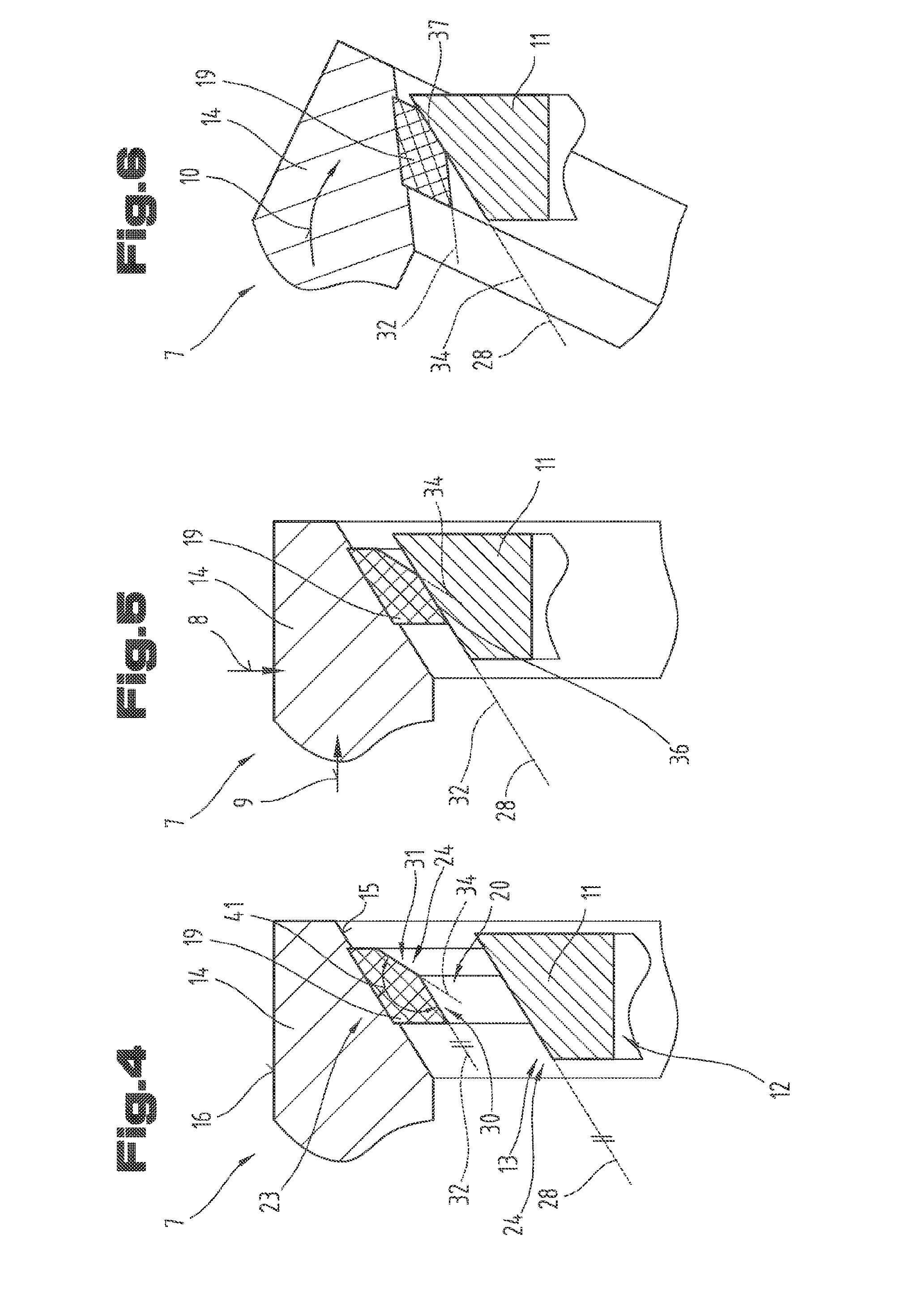
[0024] FIG. 4 shows a schematic detail diagram of the first exemplary embodiment of the bearing element in the unloaded condition;
[0025] FIG. 5 shows a schematic detail diagram of the first exemplary embodiment of the bearing element in the condition loaded with an axial force and/or a radial force;
[0026] FIG. 6 shows a schematic detail diagram of the first exemplary embodiment of the bearing element in the condition loaded with a tilting torque;
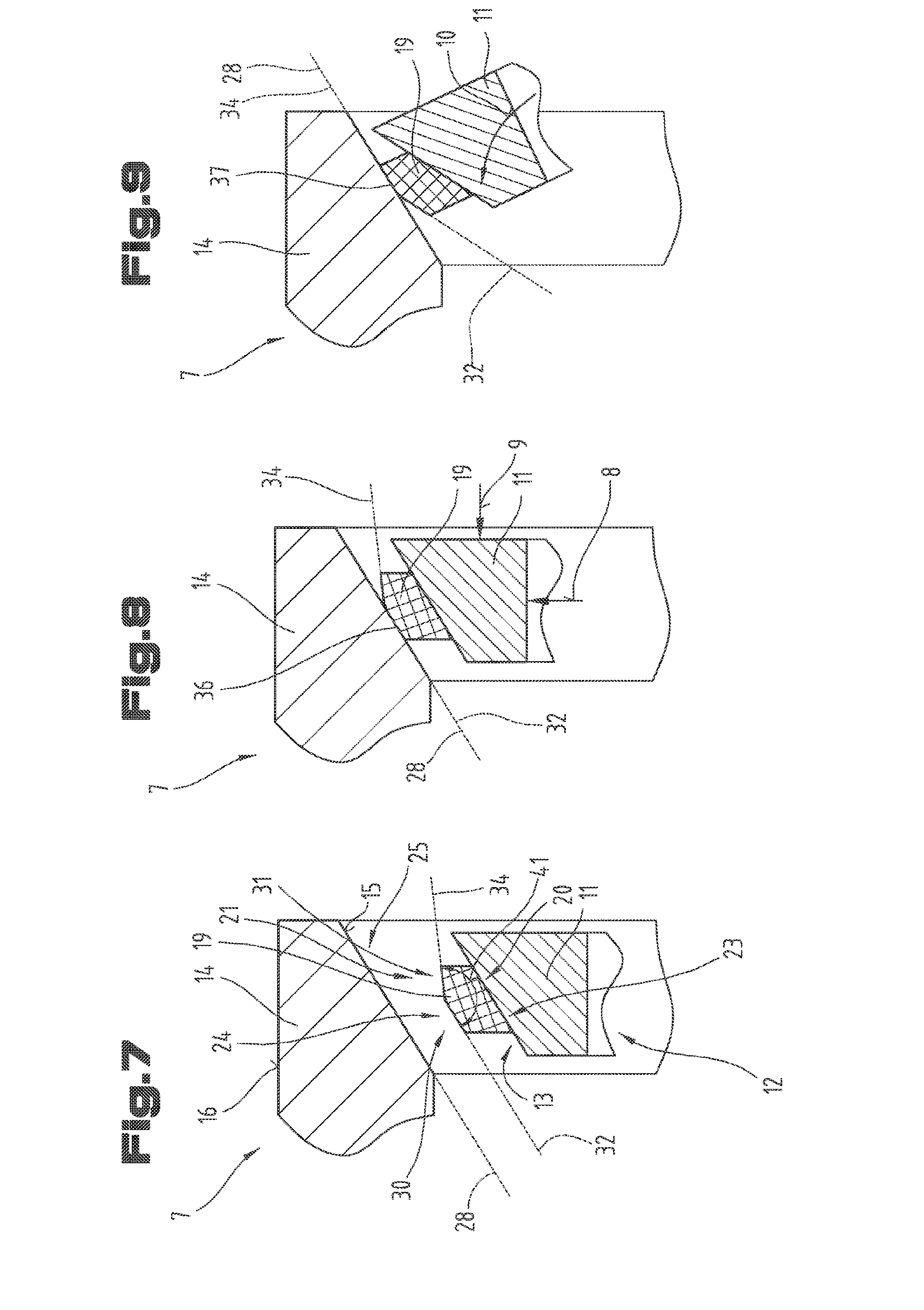
[0027] FIG. 7 shows a schematic detail diagram of a second exemplary embodiment of the bearing element in the unloaded condition;
[0028] FIG. 8 shows a schematic detail diagram of the second exemplary embodiment of the bearing element in the condition loaded with an axial force and/or a radial force;
[0029] FIG. 9 shows a schematic detail diagram of the second exemplary embodiment of the bearing element in the condition loaded with a tilting torque.
[0030] By way of introduction, it is pointed out that like parts in the differently described embodiments are denoted with like reference symbols or like structural-part designations, wherein the disclosures contained in the entire description can be carried over logically to like parts with like reference symbols or like structural-part designations. The position indications chosen in the description, such as top, bottom, side, etc., for example, are also relative to the figure being directly described as well as illustrated, and these position indications are to be logically carried over to the new position upon a position change.
[0031] FIG. 1 shows a schematic diagram of a wind turbine 1 for generation of electrical energy from wind energy. The wind turbine 1 comprises a gondola 2, which is received rotatably on a tower 3. The electrotechnical components such as, for example, generator of the wind turbine 1 are disposed in the gondola 2.
[0032] Furthermore, a rotor 4 is formed, which has a rotor hub 5 having rotor blades 6 disposed thereon. In particular, it is provided that the rotor hub 5 is received by means of a bearing element 7 in pivotably movable manner on the gondola 2.
[0033] It is of particular advantage when the bearing element 7 is designed in conformity with the descriptions provided in this document, since, especially during use of only one bearing element 7 for the bearing system of the rotor hub 5 on the gondola 2, both a radial force 8 and an axial force 9 as well as a tilting torque 10 must be absorbed by the bearing element 7. The axial force 9 is created by the force of the wind. The radial force 8 corresponds to the weight force of the rotor 4 and it acts at the center of gravity of the rotor 4. Since the center of gravity of the rotor 4 is located outside the bearing element 7, the tilting torque 10 in the bearing element 7 is caused by the radial force 8. The tilting torque 10 may likewise be caused by an uneven load of the rotor blades 6.
[0034] Alternatively to the use of the bearing element 7 in a wind turbine 1, it is also conceivable that a bearing element 7 designed in such a way is used, for example, on a slewing ring of an excavator or on another application where both a radial force 8 and/or an axial force 9 as well as a tilting torque 10 act on the bearing element 7.
[0035] The bearing elements 7 according to the invention may have, for example, a diameter between 0.5 m and 5 m. Naturally, it is also conceivable that the bearing elements 7 are smaller or larger.
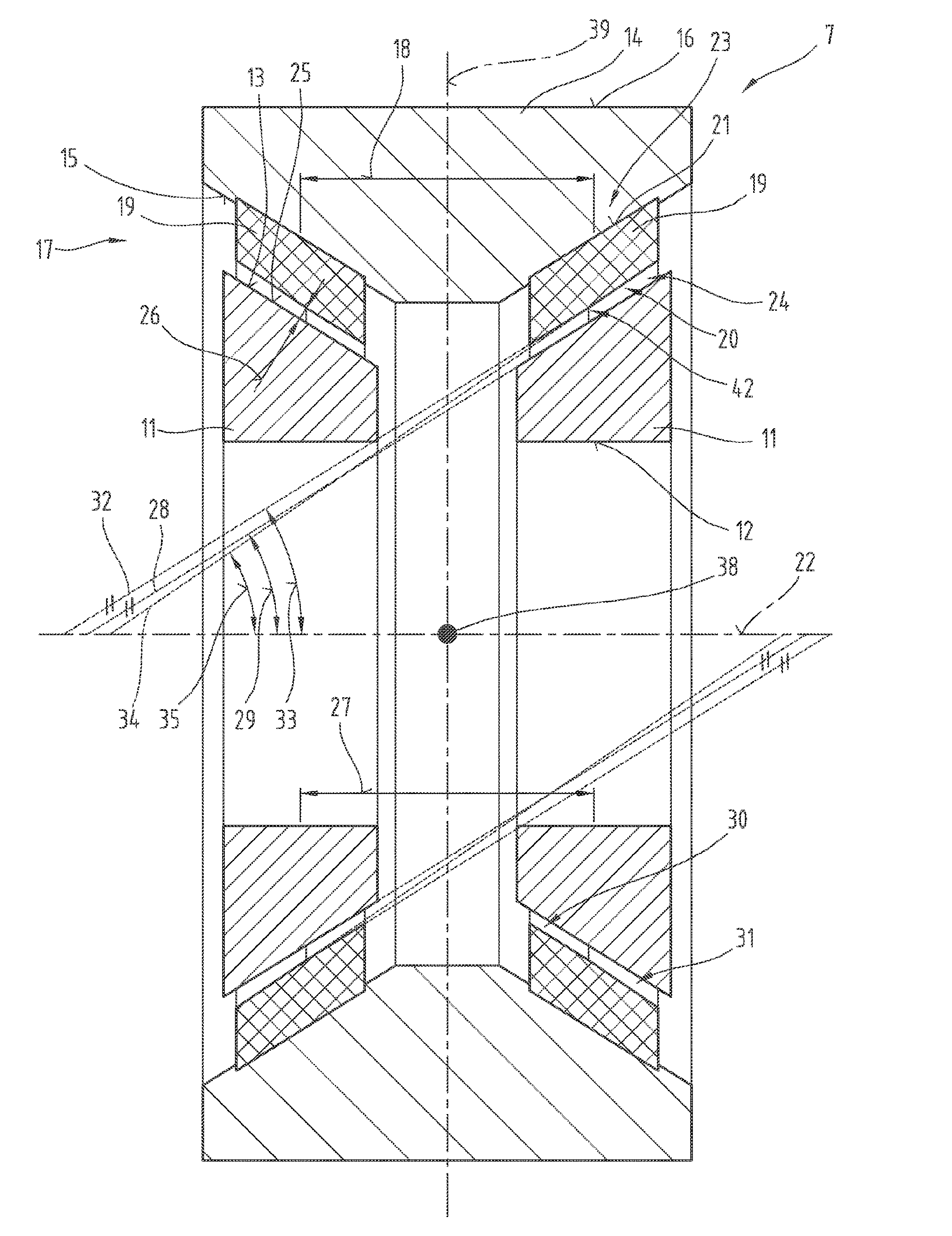
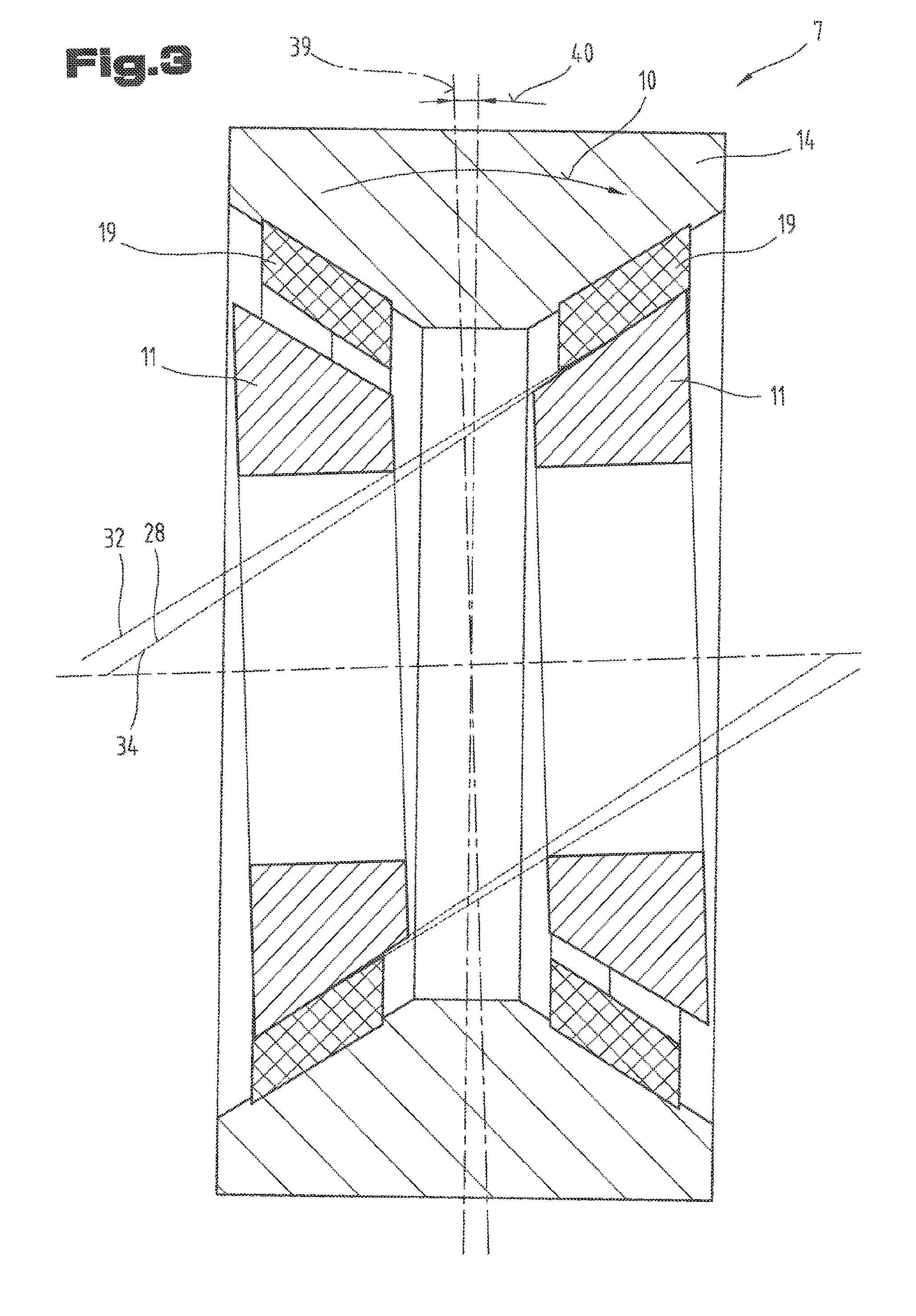
[0036] In FIG. 2, a first exemplary embodiment of the bearing element 7 is illustrated in an unloaded condition. In FIG. 3, the first exemplary embodiment of the bearing element 7 from FIG. 2 is illustrated in a condition loaded with a tilting torque 10, wherein, once again, like reference symbols or structural-part designations are used for like parts, as in the foregoing FIG. 2. In order to avoid unnecessary repetitions, the bearing element 7 will be described on the basis of an integrated view of FIGS. 2 and 3.
[0037] The bearing element 7 comprises at least one inner ring element 11, which has an inner side 12 and an outer side 13. Furthermore, an outer ring element 14 is provided, which has an inner side 15 and an outer side 16. Moreover, a sliding bearing system 17, which comprises a least two sliding bearings 19 spaced apart from one another at an axial spacing 18, is formed between the inner ring element 11 and the outer ring element 14. The two sliding bearings 19 respectively have an inner side 20 and an outer side 21.
[0038] In the diagram of FIG. 2, the bearing element 7 is illustrated in an unloaded condition. An unloaded condition is defined here as that condition in which no forces, and therefore not even any forces of gravity act on the bearing element 7. This condition is fictional and will therefore be presented merely for illustration of the structural parts and the function of the bearing element 7. As is evident from FIG. 2, in the unloaded condition of the bearing element 7, the inner ring element 11 and the outer ring element 14 and the sliding bearing 19 are disposed concentrically with respect to a common central longitudinal axis 22.
[0039] In the first exemplary embodiment of the bearing element 7, as is illustrated in FIGS. 2 to 6, the sliding bearings 19 are coupled with the outer ring element 14. In the present exemplary embodiment, the side of the sliding bearing 19 that is coupled with the outer ring element 14 is referred to as the outer side 23 of the sliding bearing. On the receiving side 23 of the sliding bearing 19, no relative movement takes place between the sliding bearing 19 and the outer ring element 14. Such a coupling of the sliding bearing 19 with the outer ring element 14 may be achieved, for example, by features such as have already been described in AT 509 625 B1.
[0040] Furthermore, it is also conceivable that the sliding bearing 19 is received in the outer ring element 14 by means of, for example, an adhesive joint. In yet another exemplary embodiment, it is also possible that the sliding bearing 19 is received interlockingly, for example, in the outer ring element 14.
[0041] In this case, the sliding bearing 19 may be subdivided into several ring segments distributed over the circumference. Furthermore, it is also conceivable that the sliding bearing 19 is designed as an individual circumferential ring. Such a circumferential ring may be inserted, for example, into the outer ring element 14, wherein, due to a frictional joint, an induced rotation of the sliding bearing 19 relative to the outer ring element 14 is suppressed.
[0042] Opposite the receiving side 23 of the sliding bearing 19, a sliding face 24 is formed, which cooperates with a running face 25 of the inner ring element 11. In the first exemplary embodiment, the outer side 13 of the inner ring element 11 is designed as the running face 25.
[0043] In the first exemplary embodiment in particular, it is provided that the sliding bearing 19 is twisted relative to the inner ring element 11, and a sliding movement between the sliding face 24 of the sliding bearing 19 and the running face 25 of the inner ring element 11 is permitted. Thereby the function of the bearing element 7 can be realized. The exact function or the exact relationships of the bearing element 7 are shown in detail in FIGS. 4 to 6, or these diagrams serve as a supplement to the understanding of the first exemplary embodiment of the bearing element 7.
[0044] Between the inner ring element 11 and the sliding bearing 19, a bearing clearance 26 is formed, as illustrated in FIG. 2.
[0045] At this place, it must be mentioned that the bearing clearance 26 is illustrated in exaggerated size for clarity, not only in FIGS. 2 and 3 but also in FIGS. 4 to 6 as well as 7 to 9. Especially in FIGS. 4 to 6 as well as 7 to 9, the geometry of the sliding-bearing system is illustrated in greatly exaggerated manner, in order to be able to illustrate the function and the technical effects clearly.
[0046] As is evident from FIG. 2, it may be provided that two inner ring elements 11 are formed, which are disposed at a spacing 27 relative to one another. The outer sides 13 of the inner ring elements 11 are respectively conically designed and turned toward one another. Due to the spacing 27 of the two inner ring elements 11 relative to one another, the bearing clearance 26 may be adjusted.
[0047] The running face 25 is a face that is designed to be rotationally symmetric with respect to the central longitudinal axis 22 and that may have the special shape of a truncated cone. Viewed in the cross section of the bearing element 7, as illustrated in FIG. 2, the running face 25 forms a straight line. If a tangent 28 is constructed on the running face 25, this tangent 28 is formed at an angle 29 with respect to the central longitudinal axis 22.
[0048] As is evident from FIG. 2, and particularly clearly in the exaggerated illustration according to FIG. 4, it is provided that the sliding bearing 19 has a first sub-portion 30 and a second sub-portion 31 on its sliding face 24.
[0049] A tangent 32 constructed on the first sub-portion 30 is disposed at an angle 33 relative to the central longitudinal axis 22. A tangent 34 constructed on the second sub-portion 31 is disposed at an angle 35 relative to the central longitudinal axis 22.
[0050] In particular, it is provided that the angle 35 of the second sub-portion 32 and the angle 33 of the first sub-portion 30 have different magnitudes. Furthermore, it is provided that the angle 29 of the running face 25 and the angle 33 of the first sub-portion 30 have the same magnitudes and thus, in the unloaded condition of the bearing element 7, the tangent 28 of the running face 25 and the tangent 32 of the first sub-portion 30 are situated parallel to one another. Considered in the three-dimensional representation, the running face 25 and the first sub-portion 30 therefore have a shell surface of a truncated cone with the same opening angle.
[0051] When the bearing element 7, as illustrated in FIG. 5, is loaded with an axial force 9 and/or a radial force 8, the first sub-portion 30 of the sliding face 24 of the sliding bearing 19 and the running face 25 of the inner ring element 11 come to bear on one another along a first contact line 36. The sliding face 24 of the sliding bearing 19 and the running face 25 of the inner ring element 11 therefore contact one another along the first contact line 36, since the radial force 8 or the axial force 9 cause a parallel shift of the two structural parts relative to one another. The parallel shift naturally varies in the range of hundredths to tenths of one millimeter, and is illustrated in greatly exaggerated manner.
[0052] However, if a tilting torque 10 is transmitted into the bearing element 7 according to the diagram in FIGS. 3 and 6, a tilting of the outer ring element 14 relative to the inner ring element 11 takes place, whereby the second sub-portion 31 of the sliding face 24 of the sliding bearing 19 bears on the running face 25 of the inner ring element 11 along a second contact line 37.
[0053] As is evident from FIG. 3, the two sliding bearings 19 then lie on the inner ring elements 11 in diagonally opposite manner. During this described tilting, a twisting of the outer ring element 14 relative to the inner ring 11 occurs in particular with respect to a fulcrum 38, which is located at the point of intersection between the central longitudinal axis 22 and a longitudinal middle axis 39.
[0054] Naturally it is ideal when, after the said tilting of the outer ring element 14, the tangent 28 of the running face 25 and the tangent 34 of the second sub-portion 31 of the sliding face 24 of the sliding bearing 19 are situated coincidingly on one another. Thereby, even during a loading of the bearing element 7 by a tilting torque 10, a linear contact therefore takes place between the sliding face 24 and the running face 25, whereby the surface pressure and thus the wear on the sliding face 24 may be reduced.
[0055] The coincidence of the tangent 24 of the second sub-portion 31 and of the tangent 28 of the running face 25 after the tilting can be achieved in that, during the construction of the sliding bearing 19 in the unloaded condition corresponding to FIG. 2, the tangent 28 on the running face 25 is taken and twisted by a certain angle with respect to the fulcrum 38, so that this forms the tangent 34 of the second sub-portion 31 and is intersected by the tangent 32 of the first sub-portion 30 at approximately the middle of the sliding bearing 19. The magnitude of this angle, by which the tangent 28 on the running face 25 is twisted during the construction of the sliding bearing 19, then determines the maximum deflection angle 40.
[0056] Between the tangent 34 of the second sub-portion 31 and the tangent 32 of the first sub-portion 30, an opening angle 41 is formed that corresponds to an angle of 180.degree. minus the maximum deflection angle 40. For correspondingly small bearing clearance 26, which varies in the range of hundredths of one millimeter to tenths of one millimeter, the maximum deflection angle 40 accordingly also lies in the range of hundredths to tenths of one degree.
[0057] Furthermore, it may be provided that a fabrication-related transition radius 42 is formed between the first sub-portion 30 and the second sub-portion 31. Preferably, the transition radius 42 will turn out to be as small as possible, so that the first contact line 36 and the second contact line 37 are as long as possible and thus the least possible surface pressure occurs between the sliding face 24 of the sliding bearing 19 and the running face 25 of the inner ring element 11. Stated in other words, in the ideal case the first sub-portion 30 and the second sub-portion 31 will adjoin one another directly or if at all possible without transition radius 42.
[0058] A further and as the case may be independent embodiment of the bearing element 7 is shown in a second exemplary embodiment in FIGS. 7 to 9, wherein once again like reference symbols or structural-part designations are used for like parts, as in the foregoing FIGS. 2 to 6. To avoid unnecessary repetitions, the detailed description in the foregoing FIGS. 2 to 6 is invoked or reference is made thereto.
[0059] In the second exemplary embodiment of the bearing element 7, it may be provided that the sliding bearing 19 is coupled with the inner ring element 11 and a sliding movement takes place between the sliding bearing 19 and the outer ring element 14.
[0060] As is evident from the second exemplary embodiment, the sliding bearing 19 may be coupled with the inner ring element 11 and thus the receiving side 23 of the sliding bearing 19 may be formed on its inner side 20. Corresponding to this, the sliding face 24 of the sliding bearing 19 in this exemplary embodiment is formed on its outer side 21 and cooperates with the inner side 15 of the outer ring element 14, which in this exemplary embodiment is formed as the running face 25.
[0061] The relationships between the first sub-portion 30 and the second sub-portion 31 of the sliding face 24 of the sliding bearing 19 and the running face 24, cooperating therewith, of the outer ring element 14 behave in a manner analogous to the first exemplary embodiment already described in FIGS. 2 to 6. For the sake of brevity, the second exemplary embodiment will therefore not be described separately in detail, but instead the function is clearly evident to the person skilled in the art on the basis of the description for the first exemplary embodiment described in FIGS. 2 to 6 or on the basis of FIGS. 7 to 9.
[0062] Such a second exemplary embodiment of the bearing element 7 having an internally disposed sliding bearing 19, as illustrated in FIGS. 7 to 9, will be used preferably when the outer ring element 14 is designed to be immovable and the inner ring element 11 together with the sliding-bearing element 19 can be twisted relative to the outer ring element 14.
[0063] The exemplary embodiments show possible embodiment variants, wherein it must be noted at this place that the invention is not restricted to the specially illustrated embodiment variants of the same, but to the contrary diverse combinations of the individual embodiment variants with one another are also possible and, on the basis of the teaching of the technical handling by the subject invention, this variation possibility lies within the know-how of the person skilled in the art and active in this technical field.
[0064] The scope of protection is defined by the claims. However, the description and the drawings are to be used for interpretation of the claims. Individual features or combinations of features from the shown and described different exemplary embodiments may represent inventive solutions that are independent in themselves. The task underlying the independent inventive solutions may be inferred from the description.
[0065] All statements about value ranges in the description of the subject matter are to be understood to the effect that they jointly comprise any desired and all sub-ranges therefrom, e.g. the statement 1 to 10 is to be understood to the effect that all sub-ranges, starting from the lower limit 1 and the upper limit 10 are jointly comprised, i.e. all sub-ranges begin with a lower range of 1 or greater and end at an upper limit of 10 or smaller, e.g. 1 to 1.7, or 3.2 to 8.1, or 5.5 to 10.
[0066] Finally, it must be pointed out, as a matter of form, that some elements have been illustrated not to scale and/or enlarged and/or reduced for better understanding of the structure.
LIST OF REFERENCE NUMERALS
[0067] 1 Wind turbine [0068] 2 Gondola [0069] 3 Tower [0070] 4 Rotor [0071] 5 Rotor hub [0072] 6 Rotor blade [0073] 7 Bearing element [0074] 8 Radial force [0075] 9 Axial force [0076] 10 Tilting torque [0077] 11 Inner ring element [0078] 12 Inner side of inner ring element [0079] 13 Outer side of inner ring element [0080] 14 Outer ring element [0081] 15 Inner side of outer ring element [0082] 16 Outer side of outer ring element [0083] 17 Sliding bearing system [0084] 18 Axial spacing [0085] 19 Sliding bearing [0086] 20 Inner side of sliding bearing [0087] 21 Outer side of sliding bearing [0088] 22 Central longitudinal axis [0089] 23 Outer side of sliding bearing [0090] 24 Sliding face of sliding bearing [0091] 25 Running face [0092] 26 Bearing clearance [0093] 27 Spacing of inner ring elements [0094] 28 Tangent of running face [0095] 29 Angle of running face [0096] 30 First sub-portion [0097] 31 Second sub-portion [0098] 32 Tangent of first sub-portion [0099] 33 Angle of first sub-portion [0100] 34 Tangent of second sub-portion [0101] 35 Angle of second sub-portion [0102] 36 First contact line [0103] 37 Second contact line [0104] 38 Fulcrum [0105] 39 Longitudinal middle axis [0106] 40 Maximum deflection angle [0107] 41 Opening angle [0108] 42 Transition radius
* * * * *
D00000
D00001
D00002
D00003
D00004
D00005
XML
uspto.report is an independent third-party trademark research tool that is not affiliated, endorsed, or sponsored by the United States Patent and Trademark Office (USPTO) or any other governmental organization. The information provided by uspto.report is based on publicly available data at the time of writing and is intended for informational purposes only.
While we strive to provide accurate and up-to-date information, we do not guarantee the accuracy, completeness, reliability, or suitability of the information displayed on this site. The use of this site is at your own risk. Any reliance you place on such information is therefore strictly at your own risk.
All official trademark data, including owner information, should be verified by visiting the official USPTO website at www.uspto.gov. This site is not intended to replace professional legal advice and should not be used as a substitute for consulting with a legal professional who is knowledgeable about trademark law.