Fan
Schaafsma; Graham M. ; et al.
U.S. patent application number 16/261665 was filed with the patent office on 2019-08-01 for fan. The applicant listed for this patent is TTI (MACAO COMMERCIAL OFFSHORE) LIMITED. Invention is credited to Stephen A. Hughett, J. Luke Jenkins, Graham M. Schaafsma, Anthony T. Tocco, J. Porter Whitmire.
| Application Number | 20190234423 16/261665 |
| Document ID | / |
| Family ID | 67391988 |
| Filed Date | 2019-08-01 |


View All Diagrams
| United States Patent Application | 20190234423 |
| Kind Code | A1 |
| Schaafsma; Graham M. ; et al. | August 1, 2019 |
FAN
Abstract
A fan may include a housing with an air inlet and an air outlet, a motor disposed in the housing, and an impeller disposed in the housing and coupled to the motor. The impeller may be operable to be rotated by the motor for drawing air into the air inlet and expelling the air from the air outlet. The fan may also include a diffuser disposed at least partially in the housing. The diffuser may have a bowl-shape and the bowl-shape may define an air diffusing surface over which the air moves towards the air outlet.
| Inventors: | Schaafsma; Graham M.; (Raleigh, NC) ; Jenkins; J. Luke; (Anderson, SC) ; Hughett; Stephen A.; (Williamston, SC) ; Whitmire; J. Porter; (Greenville, SC) ; Tocco; Anthony T.; (Easley, SC) | ||||||||||
| Applicant: |
|
||||||||||
|---|---|---|---|---|---|---|---|---|---|---|---|
| Family ID: | 67391988 | ||||||||||
| Appl. No.: | 16/261665 | ||||||||||
| Filed: | January 30, 2019 |
Related U.S. Patent Documents
| Application Number | Filing Date | Patent Number | ||
|---|---|---|---|---|
| 62624909 | Feb 1, 2018 | |||
| Current U.S. Class: | 1/1 |
| Current CPC Class: | F04D 29/547 20130101; F04D 19/002 20130101; F04D 29/441 20130101; F21V 33/0096 20130101; F04D 25/088 20130101; F04D 17/16 20130101; F21V 33/00 20130101 |
| International Class: | F04D 29/44 20060101 F04D029/44; F04D 29/54 20060101 F04D029/54 |
Claims
1. A fan comprising: a housing including: an air inlet, and an air outlet; a motor disposed in the housing; an impeller disposed in the housing and coupled to the motor, the impeller operable to be rotated by the motor for drawing air into the air inlet and expelling the air from the air outlet; and a diffuser disposed at least partially in the housing, the diffuser having a bowl-shape, and the bowl-shape defining an air diffusing surface over which the air moves towards the air outlet.
2. The fan of claim 1, wherein the air outlet comprises an annular shape.
3. The fan of claim 1, wherein the bowl-shape is inverted relative to the housing.
4. The fan of claim 1, wherein the diffuser includes one or more openings.
5. The fan of claim 1, wherein the diffuser is devoid of one or more openings.
6. The fan of claim 4, wherein the diffuser is disposed between the air inlet and the air outlet.
7. The fan of claim 1, wherein a portion of the diffuser is disposed downstream of the air outlet.
8. The fan of claim 1, wherein: the housing includes a shroud positioned around a portion of the diffuser, and a portion of the shroud is bowl-shaped and generally congruent to the diffuser.
9. The fan of claim 1, wherein a portion of the air diffusing surface faces the impeller, and wherein the air diffusing surface is at least partially convex toward the impeller.
10. The fan of claim 1, further comprising a light.
11. The fan of claim 1, wherein: the fan is configured to be mounted to a ceiling, and the air is expelled from the air outlet in a direction that is approximately orthogonal to the ceiling.
12. The fan of claim 1, wherein: the fan is configured to supported on a floor surface, and the air is expelled from the air outlet in a direction that is generally parallel to the floor surface.
13. The fan of claim 1, wherein the impeller is rotatable about an axis of rotation, and wherein a center of the diffuser is aligned with the axis of rotation.
14. The fan of claim 13, wherein the air outlet is configured to expel air in a direction parallel to the axis of rotation.
15. The fan of claim 13, wherein the air outlet is configured to expel air in a direction perpendicular to the axis of rotation.
16. A fan comprising: a housing including an air inlet and a shroud, the shroud including an inner periphery surface; an inverted bowl-shaped diffuser positioned at least partially within the housing, the diffuser including an outer periphery surface; and an air outlet defined between the inner periphery surface of the shroud and the outer periphery surface of the diffuser.
17. The fan of claim 16 further comprising: a motor positioned within the housing; and an impeller positioned within the housing, wherein the impeller is operable to be rotated by the motor for drawing air into the air inlet and expelling the air from the air outlet.
18. The fan of claim 17, wherein, the impeller is positioned between the housing and the diffuser.
19. The fan of claim 18, wherein the outer periphery surface of the diffuser is convex toward the impeller.
20. The fan of claim 16, wherein the air outlet is defined between a terminal end of the shroud and a terminal end of the diffuser.
Description
CROSS REFERENCE TO RELATED APPLICATIONS
[0001] This application claims priority to U.S. Provisional Patent Application No. 62/624,909 filed Feb. 1, 2018, the entire contents of which are incorporated herein by reference.
BACKGROUND
[0002] The present subject matter relates to fans.
[0003] Fans may be used to circulate air within rooms, dry carpets, dry floors, and/or the like. Some fans include blades or impellers positioned within a housing such that the blades or impellers are not visible to a user. Such fans are referred to as bladeless fans. A bladeless fan typically draws air through an opening in the housing and guides the air through inner pathways until the air is pushed out of the inner pathways in a given direction.
SUMMARY
[0004] In one embodiment, a fan may include a housing with an air inlet and an air outlet, a motor disposed in the housing, and an impeller disposed in the housing and coupled to the motor. The impeller may be operable to be rotated by the motor for drawing air into the air inlet and expelling the air from the air outlet. The fan may also include a diffuser disposed at least partially in the housing. The diffuser may have a bowl-shape and the bowl-shape may define an air diffusing surface over which the air moves towards the air outlet.
[0005] In another embodiment, a fan includes a housing having an air inlet and a shroud. The shroud includes an inner periphery surface. The fan may include an inverted bowl-shaped diffuser positioned at least partially within the housing. The diffuser may include an outer periphery surface. The fan may include an air outlet that is defined between the inner periphery surface of the shroud and the outer periphery surface of the diffuser.
[0006] Other aspects of the present subject matter will become apparent by consideration of the detailed description and accompanying drawings.
BRIEF DESCRIPTION OF THE DRAWINGS
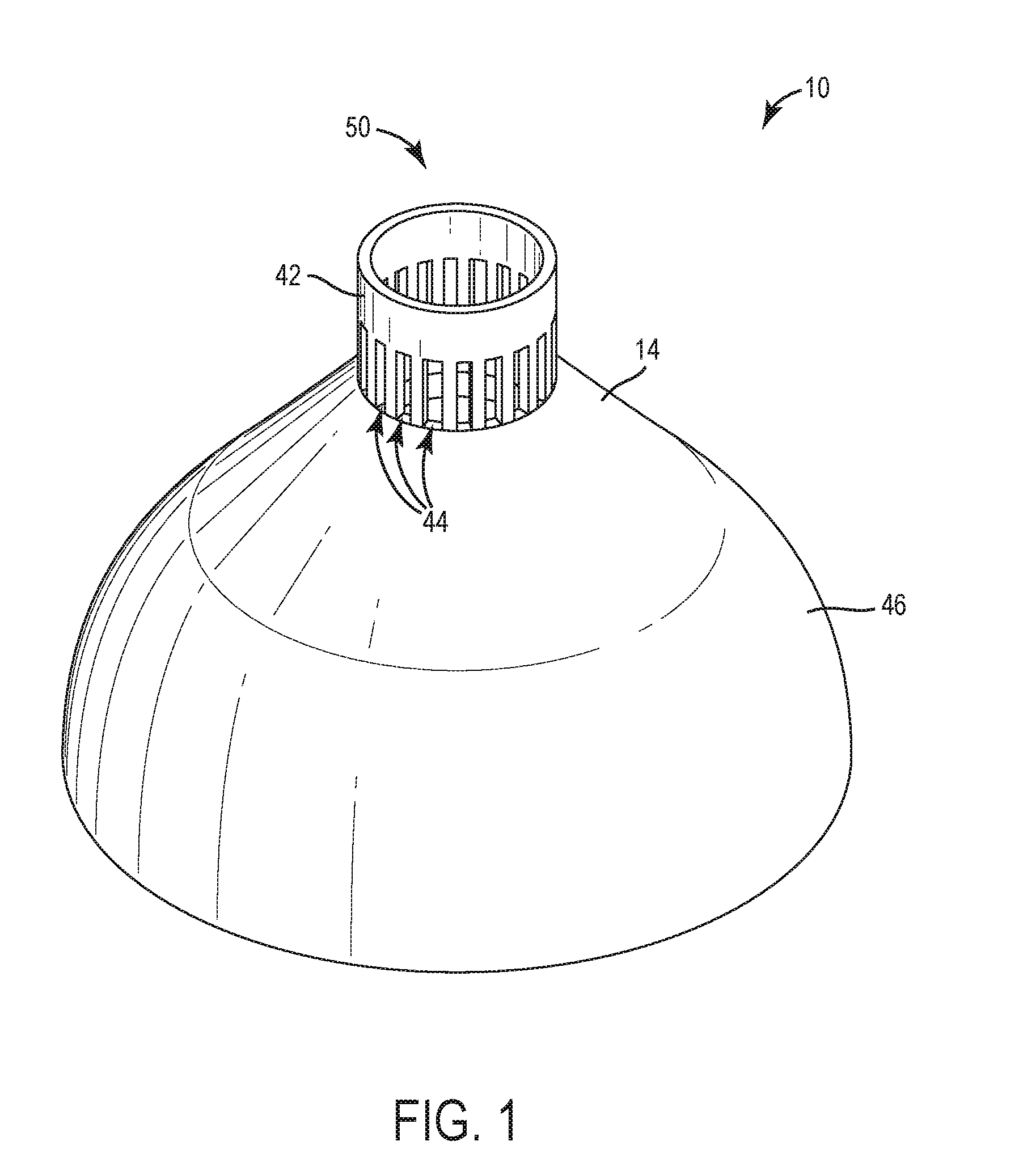
[0007] FIG. 1 is a top perspective view of a fan.
[0008] FIG. 2 is a bottom perspective view of the fan of FIG. 1.
[0009] FIG. 3 is a top view of the fan of FIG. 1.
[0010] FIG. 4 is a bottom view of the fan of FIG. 1.
[0011] FIG. 5 is a perspective cross-sectional view of the fan of FIG. 1.
[0012] FIG. 6 is a perspective view of a diffuser of the fan of FIG. 1.
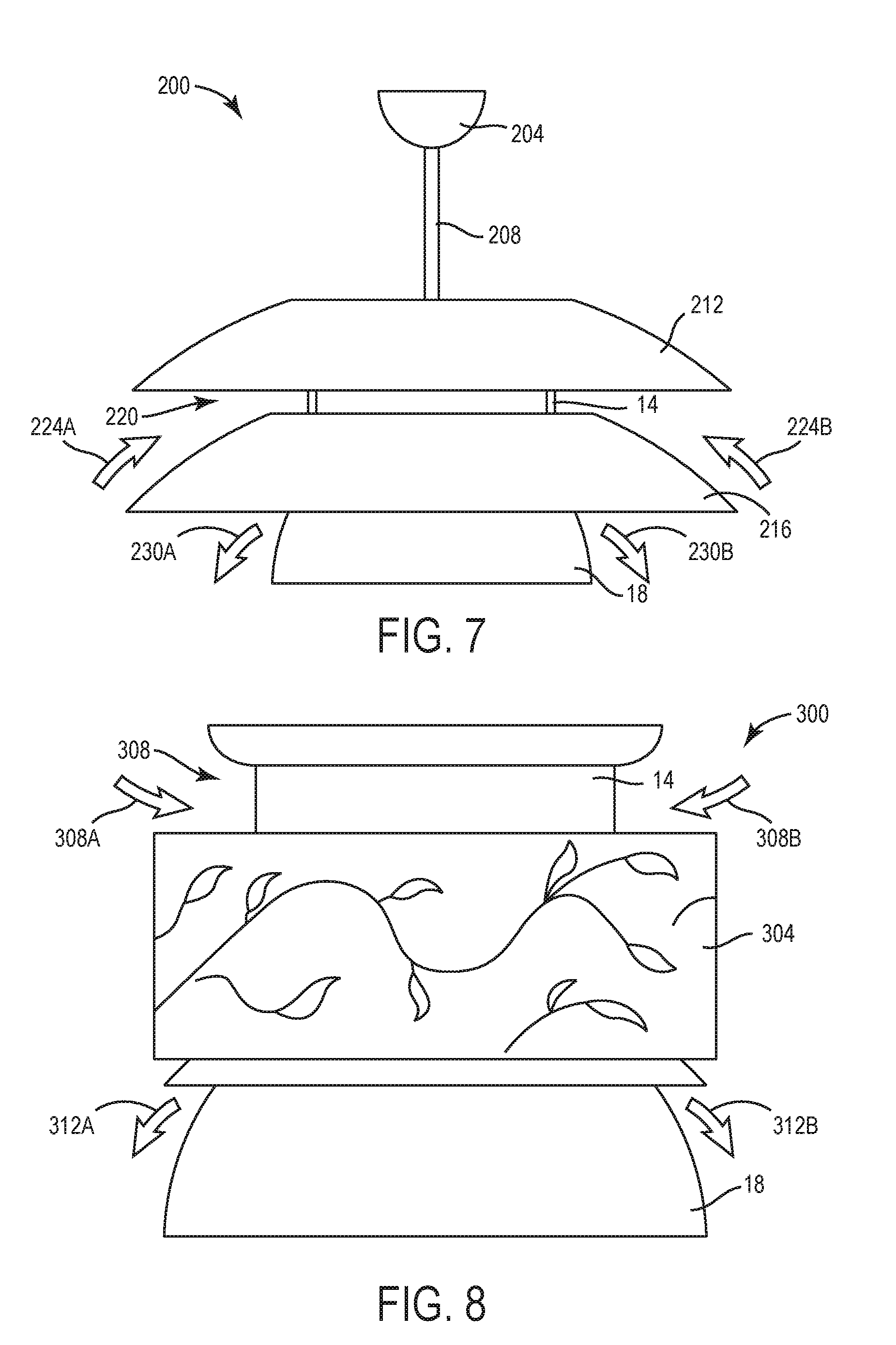
[0013] FIG. 7 is an elevation view of a fan according to another embodiment of the present subject matter.
[0014] FIG. 8 is an elevation view of a fan according to another embodiment of the present subject matter.
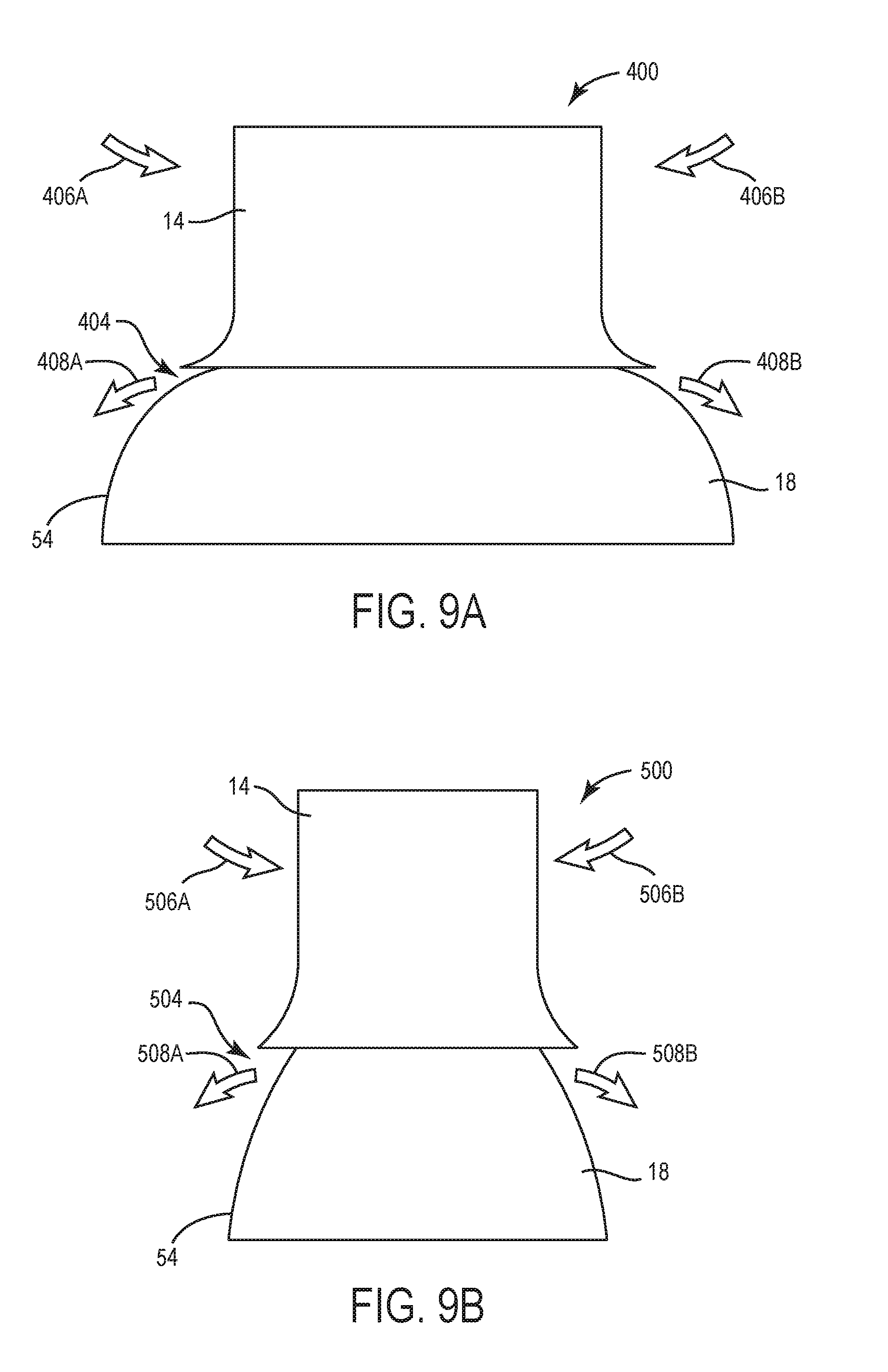
[0015] FIG. 9A is an elevation view of a fan according to another embodiment of the present subject matter.
[0016] FIG. 9B is an elevation view of a fan according to another embodiment of the present subject matter.
[0017] FIG. 10 is a front perspective view of a fan according to another embodiment of the present subject matter.
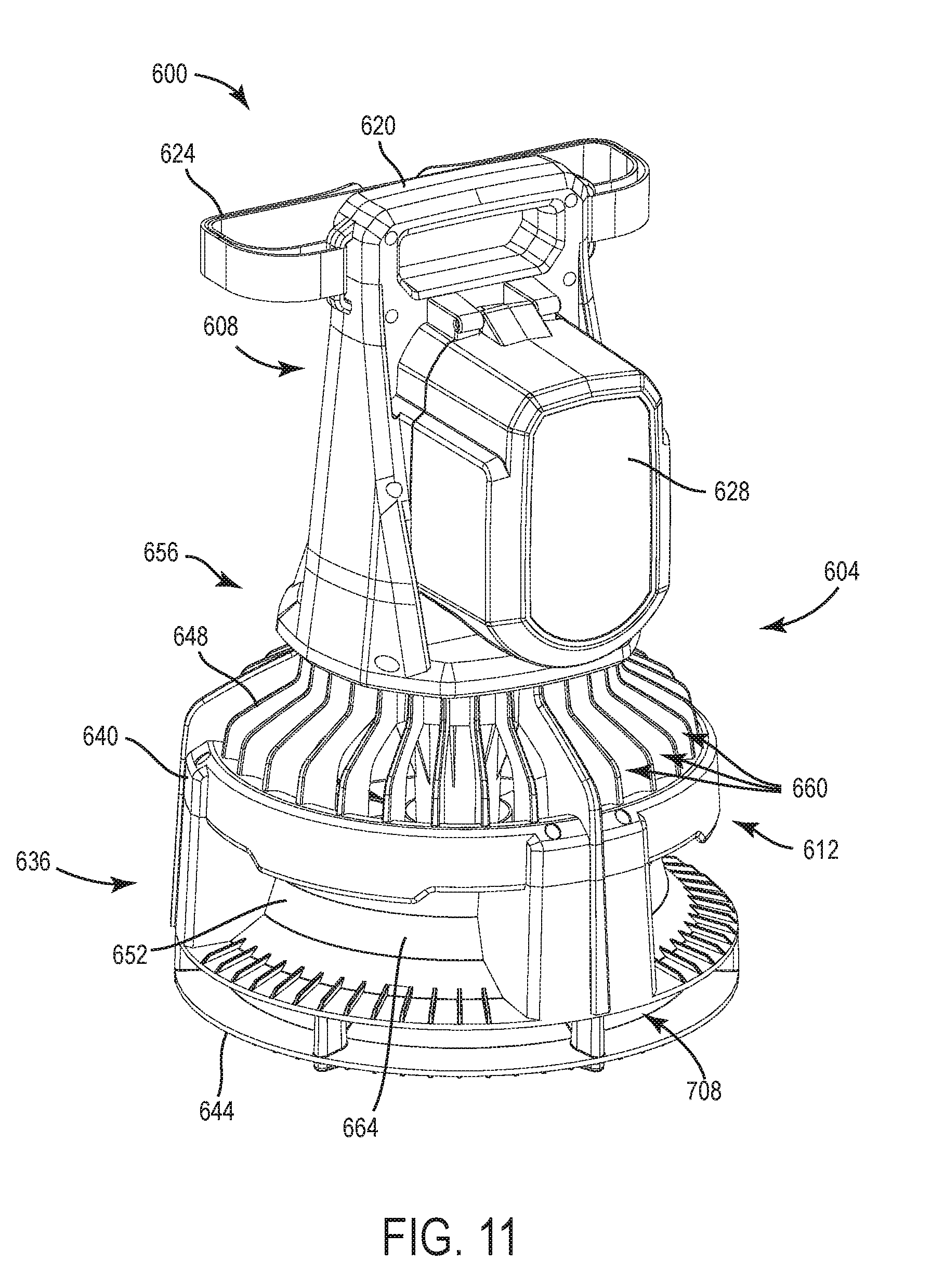
[0018] FIG. 11 is a rear perspective view of the fan of FIG. 10.
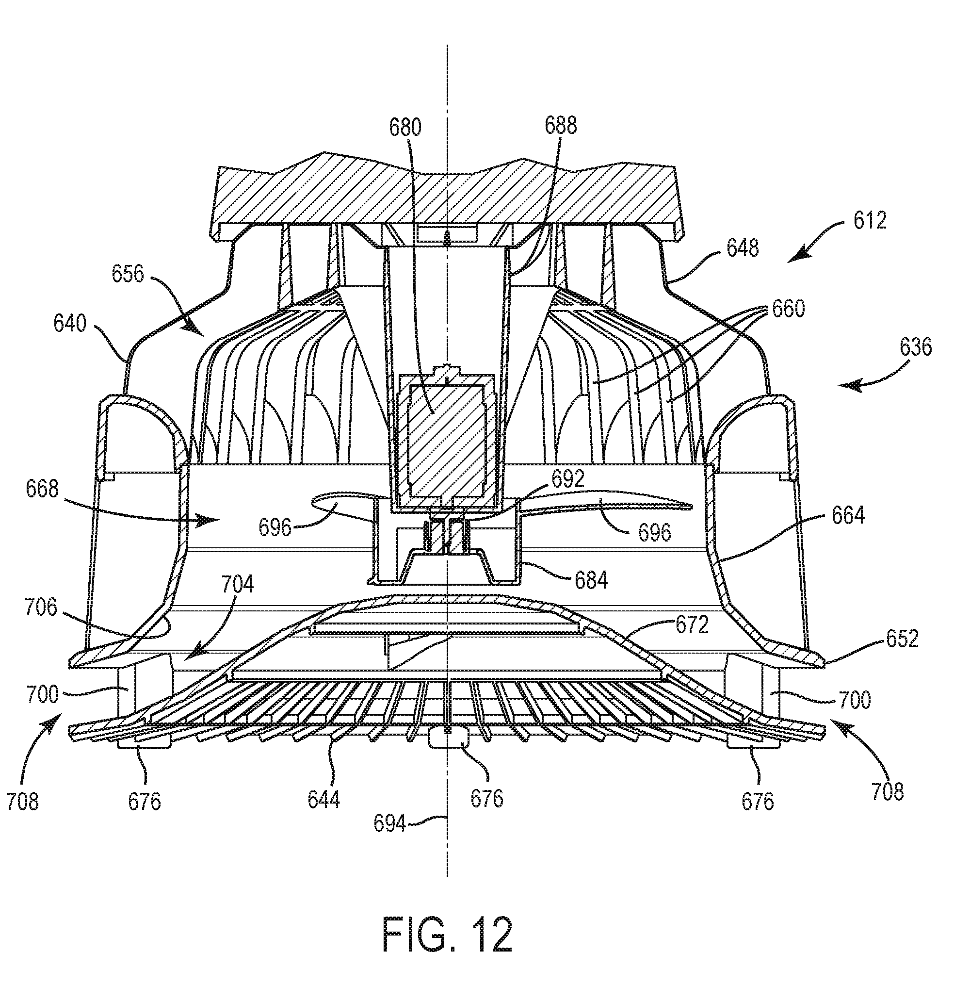
[0019] FIG. 12 is an enlarged cross-sectional view of a portion of the fan of FIG. 10.
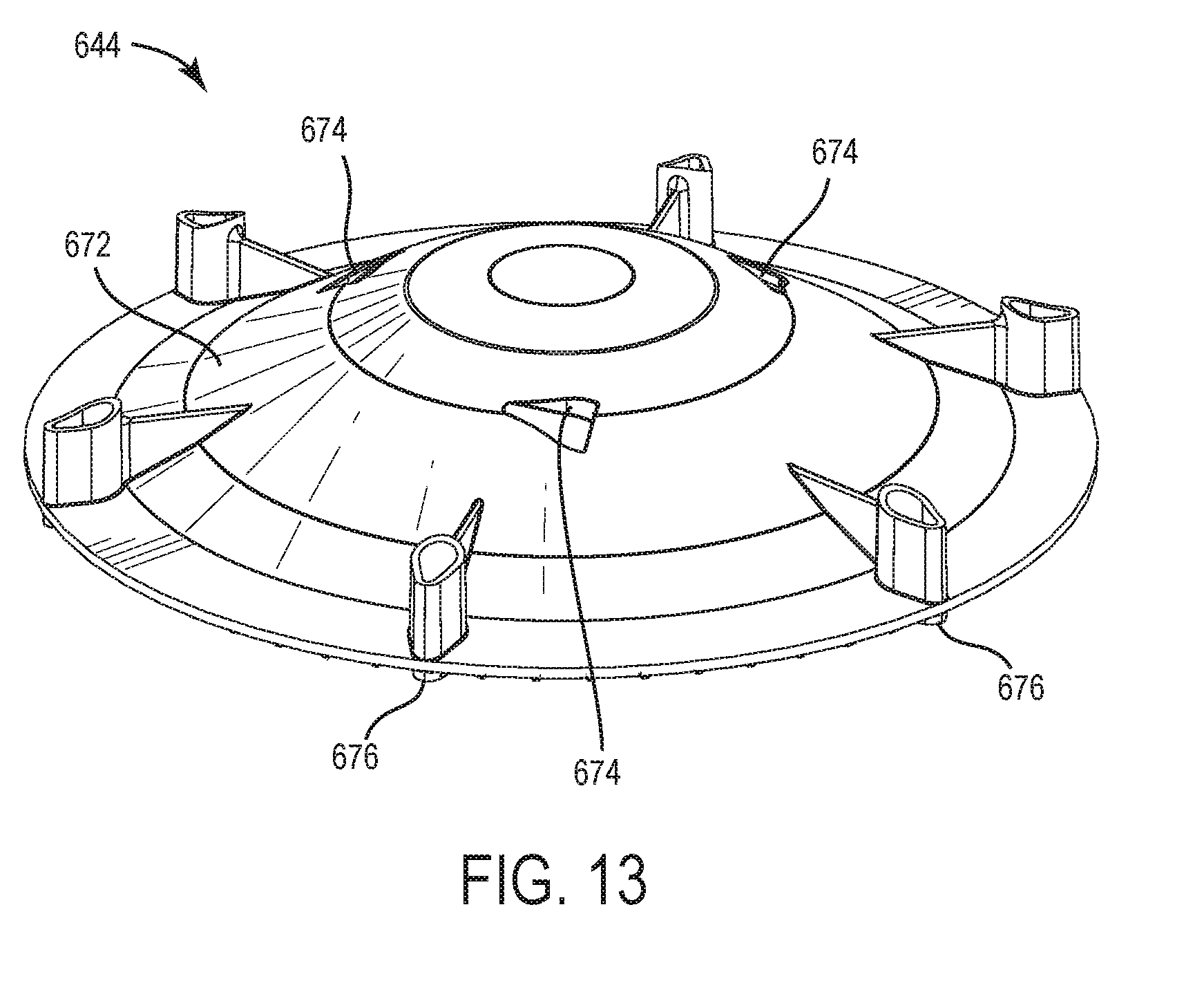
[0020] FIG. 13 is a perspective view of a diffuser of the fan of FIG. 10.
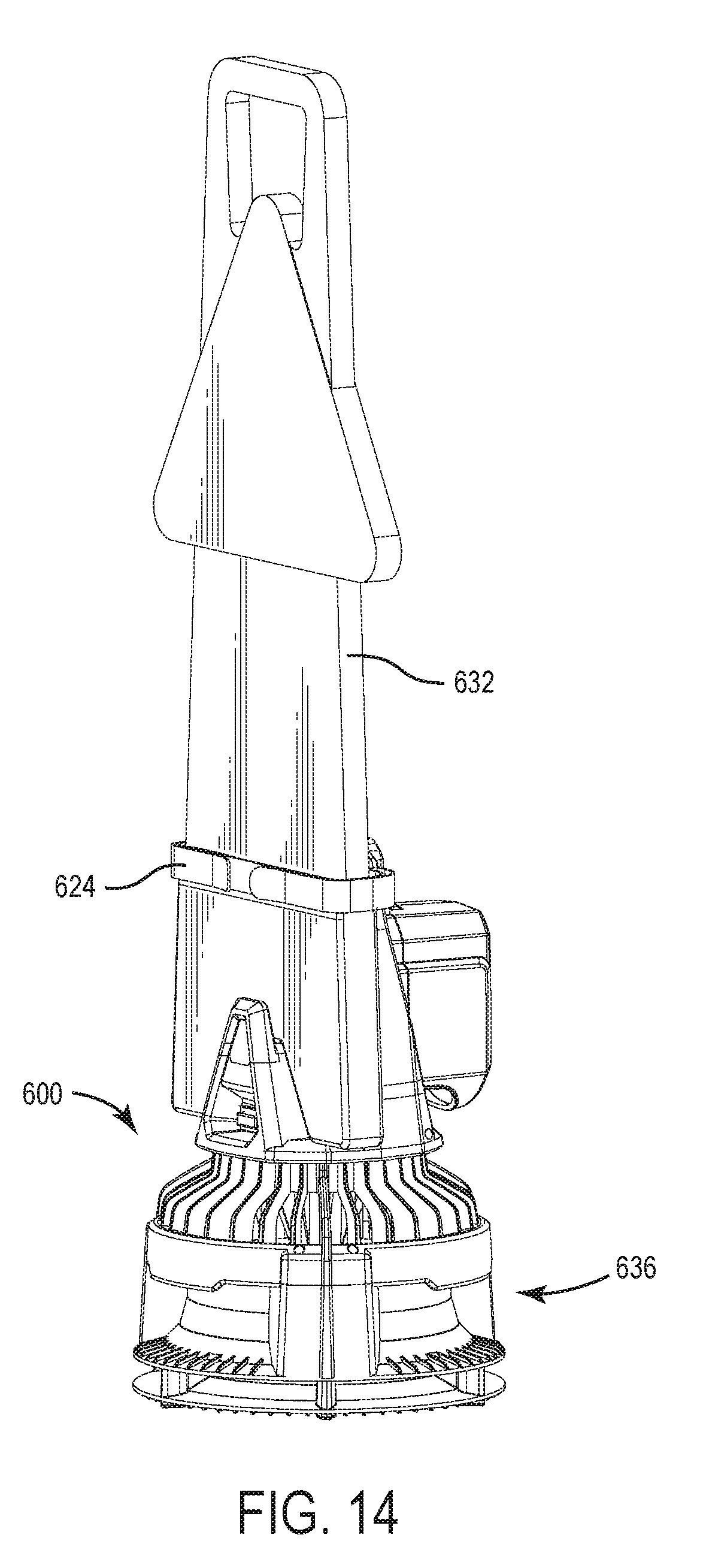
[0021] FIG. 14 is a perspective view of the fan of FIG. 10 including an accessory.
[0022] Before any embodiments are explained in detail, it is to be understood that the present subject matter is not limited in its application to the details of construction and the arrangement of components set forth in the following description or illustrated in the following drawings. The present subject matter is capable of other embodiments and of being practiced or of being carried out in various ways.
DETAILED DESCRIPTION
[0023] FIGS. 1-5 illustrate a fan, generally designated 10. As shown in the illustrated embodiments, the fan 10 may include a ceiling fan that is configured to mount to a ceiling or other overhead structure and/or surface in a room or area to create airflows within the room or area. Such airflows may be useful for improved heating of the room, improved cooling of the room, improved drying of objects in the room (e.g., improved drying of floors, rugs, carpets, and/or the like), and/or the like. Aspects of the present subject matter, however, may be applied to other types of fans, such as pedestal fans, tabletop fans, box fans, window fans, floor fans, automotive fans, centrifugal HVAC fans, and/or the like.
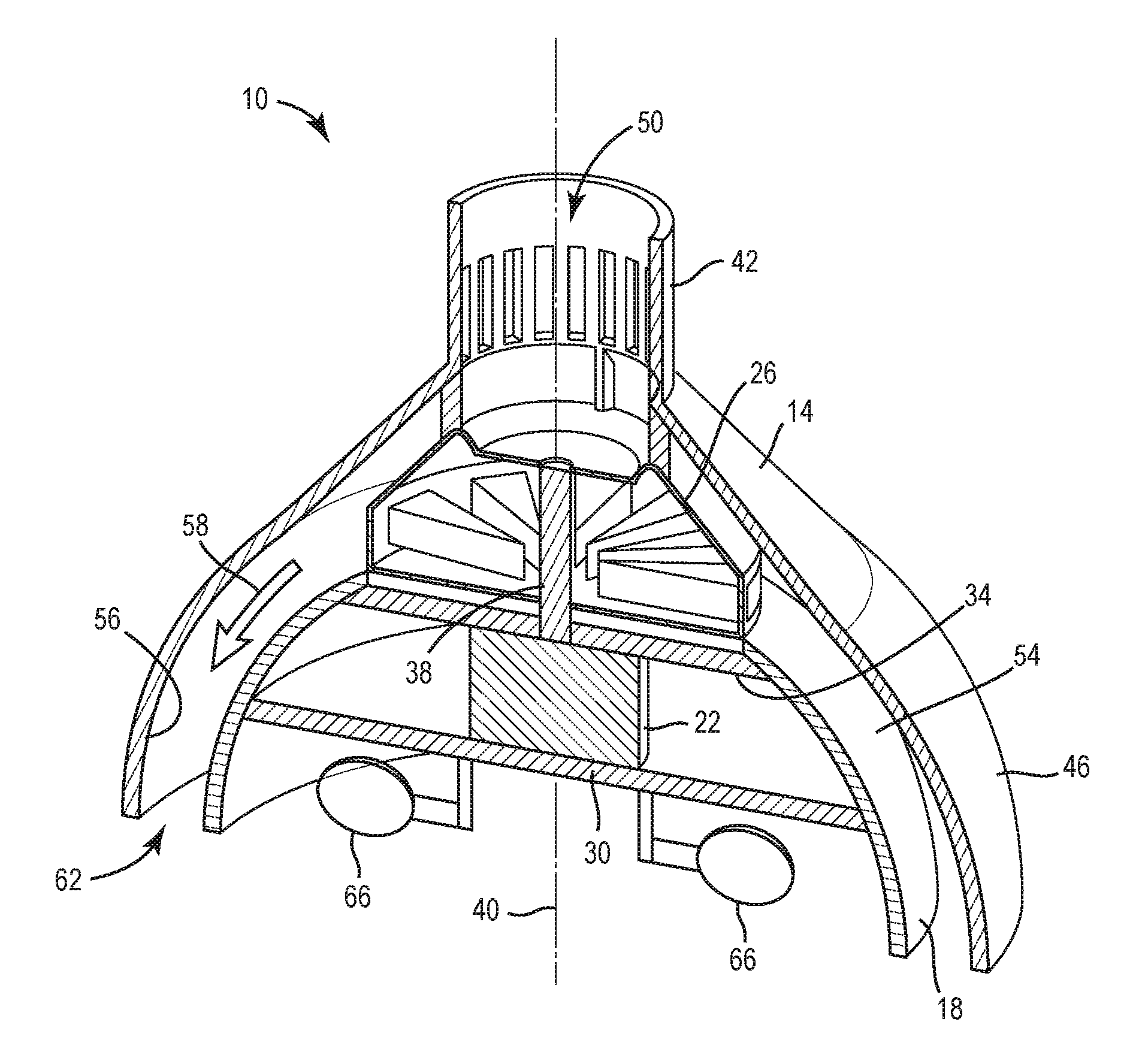
[0024] With reference to FIGS. 1-5, the fan 10 may include a housing 14 and a diffuser 18 (see e.g., FIG. 5) positioned inside the housing 14. In some embodiments, the diffuser 18 may include an inverted bowl-shaped diffuser over which air may be caused to flow as described herein. In this way, the fan 10 may output a desired airflow or air stream by way of causing air to flow on, over, through, and/or across the diffuser as described herein. As shown in the illustrated embodiment, the diffuser 18 may be entirely positioned inside the housing 14. In other embodiments, the diffuser 18 may be partially positioned inside the housing 14. In further embodiments, the diffuser 18 may not be positioned in the housing 14 (e.g., the diffuser 18 may be positioned outside of the housing 14, the diffuser 18 may be positioned adjacent to the housing 14, and/or the like). Although not illustrated, the fan 10 may include a mount coupled to the housing 14 for mounting the fan 10 to a ceiling. Additionally, or alternatively, the fan 10 may be coupled to a downrod (see e.g., 208, FIG. 7) that may be mounted to a ceiling. In some embodiments, the housing 14 and the diffuser 18 may include opposing surfaces having a same or substantially similar shape (e.g., complementary shaped surfaces) as described herein, for generating a desired airflow by way of causing air to flow between portions of the housing 14 and the diffuser 18. In this way, the airflow being output by the fan 10 may be customizable and/or controllable based on the location, size, and/or shape of the diffuser 18 and/or the housing 14. For example, the diffuser 18 and the housing 14 may, collectively or alone, provide an airflow that is omnidirectional relative to a center of the fan 10 and/or provide an airflow that is aimed in one or more preferential directions (e.g., a vertical upward direction, a vertical downward direction, a horizontal direction, and/or the like) relative to the center of the fan.
[0025] With reference to FIG. 5, the fan 10 may additionally include a motor 22 and an impeller 26 coupled (e.g., electrically coupled, mechanically coupled, and/or the like) to the motor 22. The motor 22 may be configured to rotate the impeller 26 for drawing air into the fan 10 by way of causing the air to enter one or more air inlets (e.g., see 44, FIGS. 1-2) of the housing 14 and establishing an airflow in and/or through the housing 14, or portions thereof. In some embodiments, the motor 22 and the impeller 26 may be co-located within the housing 14. For example, and as FIG. 5 illustrates, in some cases the motor 22 may be positioned inside the diffuser 18 and the impeller 26 may be positioned between the housing 14 and the diffuser 18, or portions thereof. Other locations and/or positions of the motor 22 and impeller 26 are contemplated. The motor 22 may be supported within the diffuser 18 by a first mount plate 30 and/or a second mount plate 34. The first mount plate 30 may include a mount plate configured to support one or more lights (see e.g., 66, FIG. 5) and/or light sources, and the second mount plate 34 may be configured to support the motor 22. In some embodiments, the second mount plate 34 may be configured to restrain the motor 22 from vibrating and/or moving during operation of the fan 10.
[0026] In some embodiments, the motor 22 may be electrically coupled to a power source (not shown) located in the room in which the fan 10 is located, positioned, and/or otherwise disposed. In some embodiments, the power source may be an AC power source disposed in a building (e.g., a home, an office, a school, a retail store, and/or the like). Additionally, or alternatively, in some embodiments, the power source may include a battery and/or a battery pack that may be removably coupled to the fan 10. The impeller 26 may be supported on, over, and/or by the second mount plate 34 and be coupled to an output shaft 38 of the motor 22 for rotation therewith to induce an airflow, for example, based on the motor 22 receiving power from the power source. The motor 22 and the impeller 26 may be axially aligned along an axis of rotation 40 that centrally extends through the fan 10.
[0027] Referring to FIGS. 1-5, the housing 14 may include an air inlet region 42 and/or a shroud 46. In some embodiments, the air inlet region 42 may include one or more air inlets 44 or vents formed therein, through which air may enter and/or be drawn into the fan 10. The shroud 46 may be disposed on, over, around and/or otherwise surround the diffuser 18, in some cases. As shown in the illustrated embodiment, the air inlet region 42 and the shroud 46 may be integrally formed as a single member or piece of the housing 14. In other embodiments, the air inlet region 42 and/or the shroud 46 may be formed as separate members of the housing (e.g., being separate and discrete from the housing 14) and be selectively coupled to each other and/or the housing 14. The air inlet region 42 may additionally, or alternatively define at least one primary opening 50 by which air may enter the fan 10. Moreover, in instances where the fan 10 operates by way of receiving AC power, one or more electrical wires or connectors (not shown) may be routed through the primary opening 50 for powering electrical components such as the motor 22, the lights 66, sensors, controls, and/or the like. As shown in the illustrated embodiment, the air inlet region 42 may be positioned above the impeller 26 (e.g., more proximate to a first, top end of the fan 10, more proximate to a ceiling, and/or the like), however, the air inlet region 42 may be positioned elsewhere on the fan 10 (e.g. around a perimeter of the housing 14, in the shroud 46, and/or the like).
[0028] In some embodiments, the shroud 46 may include a bowl-shape that is similar, or substantially similar, to the bowl-shape of the diffuser 18. The shroud 46 may be positioned around the diffuser 18 to surround the diffuser 18. That is, in some embodiments, the diffuser 18 may be nested (e.g., fully or partially nested) respective to the shroud 46. In some embodiments, the shroud 46 and the diffuser 18 may be generally congruent. In other words, the shroud 46 and the diffuser 18 may include a same general shape, such as an inverted bowl-shape. In other embodiments, the shroud 46 and the diffuser 18 may include different shapes. In some embodiments, the diffuser 18 and the shroud 46 may be symmetric, or substantially symmetric, respective to a central axis of the diffuser 18, a central axis of the shroud 46, a central axis of the fan 10, and/or the axis of rotation 40 of the impeller 26. One or more of the central axis of the diffuser 18, the central axis of the shroud 46, the central axis of the fan 10, and/or the axis of rotation 40 of the impeller 26 may be aligned and co-axial, or non-aligned and non-co-axial. Asymmetric diffusers 18 and/or asymmetric shrouds 46 are also contemplated. As examples, and in some embodiments, the shroud 46 and/or the diffuser 18 may, together or alone, be provided in a concave shape (e.g., a concave-up shape, a concave-down shape, and/or the like), a convex shape, a shape including convex and/or convex surfaces, and/or the like. Air may be drawn into the shroud 46 by way of rotating the impeller 26 and pulling the air into the fan 10 through the air inlets 44 and/or the primary opening 50 of the air inlet region 42.
[0029] Referring now to FIGS. 5 and 6, the diffuser 18 may be positioned in the housing 14 and/or the shroud 46 of the fan 10. The diffuser 18 may include an air diffusing surface 54 disposed on, over, and/or formed by an outer peripheral surface of the diffuser 18, facing the housing 14 and/or the shroud 46. The air diffusing surface 54 may be convex, or substantially convex, and define an inverted bowl-shape of the diffuser 18. A center of the diffuser 18 may be aligned with the axis of rotation 40 of the impeller 26, a center of the housing 14, a center of the shroud 46, and/or a center of the fan 10 in some embodiments. Although the diffuser 18 may include and/or be referred to as bowl-shaped in the illustrated embodiment, the diffuser 18 may include and/or be referred to as other shapes. For example, the diffuser 18 may include and/or be referred to as half spherically shaped, bell-shaped, or as a shape corresponding to a frustum of a sphere. In other embodiments, the diffuser 18 may include another shape (e.g., a non-bowl-shape) such as a conical shape, a frusto-conical shape, an annular shape, an arcuate shape, a curvilinear shape, a convoluted shape, a cylindrical shape, an elliptical shape, a helical shape, and/or the like. In this way, the airflow exiting the fan 10 may be customized in shape, direction, velocity, and/or the like, based on customizing the size and/or shape the diffuser 16, the housing 14, and/or the shroud 46, together, or alone.
[0030] Now referring to FIG. 5, an air passageway 58 may be defined between the air diffusing surface 54 of the diffuser 18 and an inner surface 56 of the shroud 46. The air passageway 58 may be in fluid communication with the air inlet region 42. In other words, the air passageway 58 may receive air that has been drawn through the air inlet region 42 upon rotation of the impeller 26. The air passageway 58 may be formed in an annular shape (e.g., relative to a center of the fan 10) and occupy a majority of the space disposed between the diffuser 18 and the shroud 46. The air passageway 58 may terminate proximate to and/or at an air outlet 62 defined between lower, terminal ends of the diffuser 18 and the shroud 46. The air outlet 62 may include an annular shape (e.g., relative to a center of the fan 10) from which air may be expelled from the fan 10 and/or a portion of the fan 10 (e.g., air may be expelled from the housing 14, from the shroud 46, from the diffuser 18, and/or the like). In some embodiments, the air may be expelled from the space between the diffuser 18 and the housing 14 and/or the space between the diffuser 18 and the shroud 46 omnidirectionally relative to a center of the fan 10. In other words, the air outlet 62 may be in fluid communication with the air passageway 58 to expel air forced through the air passageway 58 by the impeller 26. In this way, the air may be expelled in a preferential direction as defined by the surfaces forming the air outlet 62, towards a surface or object.
[0031] As shown in FIGS. 2, 4, and 5, the fan may include one or more lights 66 that are mounted to the first mount plate 30. In the illustrated embodiment, two lights 66 are mounted proximate to the diffuser 18, which may form an inverted bowl-shape around the lights 66. In this way, the diffuser 18 may improve reflection of light being emitted by the lights 66 in addition to diffusing and expelling air from the fan 10. In some embodiments, less than one light 66 may be provided per fan, only one light 66 may be provided per fan 10, or more than two lights 66 may be provided per fan 10. In some embodiments, the lights 66 may be mounted to the housing 14 or other parts of the fan 10. The lights 66 may include light bulbs (e.g., incandescent bulbs, LED bulbs, and/or the like), however, other types of lights and/or lighting sources forming the lights (e.g., LED lighting sources, incandescent lighting sources, fluorescent lighting sources, and/or the like) are contemplated.
[0032] During operation of the fan 10, the motor 22 is configured to rotate the impeller 26 to draw air from outside the fan 10 into the fan 10, for example, by pulling the air in through the air inlets 44 and/or the primary opening 50 in the air inlet region 42. The impeller 26 may cause the air to flow into the air passageway 58. When the air is in the air passageway 58, the impeller 26 may continue to rotate for moving (e.g., forcing, driving, propelling, and/or the like) the air over the air diffusing surface 54 and out of the fan 10 through the air outlet 62. Due to the shape of the air diffusing surface 54, the air may be forced over and/or across the air diffusing surface 54 as the air is expelled from the air outlet 62. In this way, the diffuser 18 may produce an improved, more evenly distributed airflow as the air travels out of and/or away from the fan 10. The air may also be generally directed in a direction downwards (e.g., away from a ceiling) from the fan 10 by way of the shape of the diffuser 18, the housing 14, and/or the shroud 46. For example, air being expelled from the air outlet 62 may be directed in a direction approximately orthogonal to a ceiling that the fan 10 may be mounted to. Other types of fans having a diffuser 18, such as a table fan, may expel air from the fan in a generally horizontal direction (e.g., parallel to a surface supporting the fan). In this way, the diffuser 18 may improve the directional flow of the air being output by the fan 10.
[0033] Referring to FIG. 6, the diffuser 18 and the air diffusing surface 54 may be solid and/or devoid of any openings so that air may not pass through the diffuser 18. In other embodiments, the diffuser 18 may include vents to allow air to pass through the diffuser 18 to an area positioned within or underneath the diffuser 18. In this way, some air may be forced through the diffuser 18 for improving heat dissipating capabilities of the fan 10 (e.g., the air may dissipate heat from the lights 66) and/or floor drying abilities of the fan 10. Additionally, the air diffusing surface 54 of the diffuser 18 may be smooth or textured (e.g., dimpled, ridged, include linear portions, etc.) to toggle whether the air expelled from the air outlet 62 is turbulent or laminar.
[0034] FIG. 7 illustrates a fan 200 according to another embodiment. The fan 200 may be similar to the ceiling fan 10 described above, with like features being represented by like reference numerals. As shown the illustrated embodiment, the fan 200 may include a mount 204 and/or a downrod 208 that positions the fan 200 a distance away from a ceiling. The mount 204 may be coupled to the ceiling of a room using suitable fasteners (not shown). The downrod 208 may be coupled to the ceiling mount 204 at one end and to a first, top end of the housing 14 of the fan 200 at another end. In some embodiments, the downrod 208 may be provided in a variety of lengths. For example, the downrod 208 may include a length that is greater than about 1 inch, greater than about 2 inches, greater than about 8 inches, greater than about 60 inches, less than about 96 inches, less than about 24 inches, and/or the like, and/or any range or subrange thereof. The fan 200 may include a first shade 212 and a second shade 216. The shades 212, 216 may be provided to diffuse air entering and/or exiting the fan 200. Alternatively, the shades 212, 216 may provide an aesthetic look to the fan 200. The first shade 212 may be positioned proximate a top of the housing 14 (e.g., more proximate to a ceiling) of the fan 200. The second shade 216 may be positioned proximate to the inverted bowl-shaped diffuser 18, for example, and between the first shade 212 and the diffuser 18, in some cases. An air inlet 220 may be disposed between the first and second shades 212, 216, in some embodiments. An impeller (e.g., 26, FIG. 5, not visible in this view) may be configured to draw in air, which may be directed towards and/or into the interior of the housing 14 by way of pulling the air through the air inlet 220 as indicated by arrows 224A, 224B. Air may then be expelled through an air outlet (e.g., 62, FIG. 5, not visible in this view) that is disposed adjacent the second shade 216 as indicated by arrow 230A, 230B. Additionally, the second shade 216 may replace the shroud 46 of the housing 14. Although, in some embodiments, the shroud 46 and the second shade 216 may be used in conjunction. In this way, the second shade 216 may act to diffuse the expelled air from a wider area or space on, over, and/or around the diffuser 18. This may provide a larger area that the expelled air is distributed about. Alternatively, air may be expelled at a lower velocity upon exit for more subtle cooling.
[0035] FIG. 8 illustrates a fan 300 according to another embodiment. The fan 300 may be similar to the fan 10 described above, with like features being represented by like reference numerals. In the illustrated embodiment, the fan 300 includes a decorative cover 304 that forms the housing and/or is positioned around the housing 14. The decorative cover 304 may include a variety of patterns shapes, colors, and designs. In some embodiments, the decorative cover 304 may be replaceable with another decorative cover 304 of a user's preference. Operation of the ceiling fan 300 is similar to the ceiling fan 10; however, air may be drawn through an air inlet 308 at a position above the decorative cover 304 as indicated by arrows 308A and 308B. The air may then be expelled through an air outlet (such as the air outlet 62 of FIG. 5) positioned beneath the cover 304 adjacent the diffuser 18 as indicated by arrows 312A and 312B.
[0036] FIGS. 9A and 9B illustrate fans 400, 500 according to other embodiments. The fans 400, 500 may be similar to the fan 10 described above, with like features being represented with like reference numbers. The fans 400, 500 are similar to each other, but such fans and/or features thereof may vary in size. In some embodiments (e.g., FIG. 9A), the diffuser 18 and the housing 14 may be larger and include a bigger impeller to produce a greater airflow. In other words, the fan 400 may include a housing with a greater volume to fit a more powerful motor. Additionally, the diffuser 18 may include an air diffusing surface with more surface area to distribute the air over a larger area. Alternatively, in some embodiments (e.g., FIG. 9B), the diffuser 18 and the housing 14 may be smaller to produce a smaller airflow. In other words, the fan 500 may include a housing with a smaller volume to fit a less powerful motor. In addition, the diffuser 18 may include an air diffusing surface with less surface area to distribute air over a smaller area. In this way, the user may select a fan 400, 500 suitable for differently sized rooms or areas. In the illustrated embodiments, the diffuser 18 is partially positioned in the housing 14 to define an annular outlet 404 through which air is expelled. Operation of the ceiling fans 400, 500 may be similar to the ceiling fan 10; however, air may enter the fans 400, 500 through the housing 14 as indicated by arrows 406A, 506A and 406B, 506B. Air then exits the housing 14 through an annular outlet 404, 504, as indicated by arrows 408A, 508A and 408A, 408B and is caused to move over the air diffusing surface 54 as the air travels away from the fans 400, 500.
[0037] FIGS. 10-14 illustrate a fan 600 according to another embodiment. As shown in the illustrated embodiment, the fan 600 may include a floor fan (e.g., a floor blower, a floor dryer, and/or the like) for positioning on and/or over a floor, in some cases, to dry the floor.
[0038] The illustrated fan 600 includes a housing 604 having an upper section 608 and a lower section 612. The upper section 608 may include a battery receptacle (not shown) for attachment of a battery and/or a battery pack, an actuator 616 (e.g., power button), a handle 620, and/or a strap 624. A battery cover 628 may be provided for protecting the battery receptacle and/or the battery pack received in the battery receptacle. The battery pack may provide power to the fan 600 when the actuator 616 has been actuated (e.g., depressed, touched, and/or the like) by a user. The battery and/or battery pack may be rechargeable and may be selectively detached from the battery receptacle. In other embodiments, the fan 600 may be powered using an A/C source (e.g., via a power cord).
[0039] The handle 620 may allow a user to easily transport the fan 600 to various locations of a floor where the fan 600 may be used. As illustrated, the handle 620 may extend upwardly from the upper section 608 of the housing 604. In other embodiments, the handle 620 may be located elsewhere on the fan 600, and/or the fan 600 may include multiple handles 620, and/or the fan 600 may be devoid of a handle 620.
[0040] The strap 624 may be attached to any portion of the fan 600, for example, the strap 624 may be attached to the handle 620 in some embodiments. The strap 624 may be used to selectively support and/or attach an accessory, such as, for example, a wet floor sign 632 (FIG. 14) or other signage and/or types of accessories that may be used in conjunction with the fan 600. In other embodiments, other suitable coupling mechanisms (e.g., clips, clamps, bands, hooks, and/or the like) may be used to releasably attach, hold, and/or support the accessory on or over the fan 600. In some embodiments, the strap 624 may be omitted.
[0041] In some embodiments, the upper section 608 of the housing 604 may include lights or other safety signals to warn pedestrians of a wet floor or of the fan 600. In this way, the fan 600 may be used to mark or define areas where foot traffic should be avoided.
[0042] In some embodiments, the lower section 612 of the housing 604 may define a fan assembly 636 including a fan housing 640 and a diffuser 644 positioned at least partially in the fan housing 640. In some embodiments, the diffuser 644 may include a bowl-shaped diffuser (e.g., an inverted bowl-shaped diffuser) and/or be formed as an inverted bowl-shaped diffuser as described above. The fan housing 640 may include an upper portion 648 and a lower portion 652. The upper portion 648 may be disposed proximate to where the upper section 608 of the housing couples to the lower section 612 of the housing 604. The upper portion 648 may define an air inlet 656 for the fan assembly 636. The air inlet 656 may include one or more openings 660 (e.g., inlets, vents, and/or the like) that allow air to enter the fan housing 640. The lower portion 652 of the fan housing 640 may define a shroud 664 of the fan assembly 636. The upper portion 648 and the lower portion 652 may define an air chamber 668 (see, e.g., FIG. 12) of the fan housing 640.
[0043] Referring now to FIG. 12, the diffuser 644 may be positioned towards the bottom of the fan 600 (e.g., proximate to a surface supporting the fan 600, proximate to a surface to be dried, and/or the like) to support the fan 600 on or over a floor or other surface. The diffuser 644 may partially extend into the air chamber 668 defined by the fan housing 640. The diffuser 644 may include an air diffusing surface 672 formed by and/or on an external peripheral surface. The air diffusing surface 672 may be convex, or substantially convex, and define portions of the bowl-shape of the diffuser 644. In some embodiments, the air diffusing surface 672 may be formed by one or more linear segments that collectively form the overall substantial bowl-shape of the diffuser 644.
[0044] Referring to FIG. 13, the diffuser 644 may be similar to the diffuser 18 of the fan 10 described above and as such, may be referred to using similar terms. Alternately, the diffuser 664 may include vents 674 in the air diffusing surface 672 to allow some portion of the surface on which the fan 600 may be disposed to be dried by the airflow. Similar to the diffuser 18, the air diffusing surface 672 may be solid and/or devoid of any openings so that air may not pass through the diffuser 18. In this way, some air may be forced through the diffuser 644 for improving heat dissipating capabilities of the fan 10 and/or floor drying abilities of the fan 10. Additionally, the air diffusing surface 672 of the diffuser 664 may be smooth or textured (e.g., dimpled, ridged, include linear portions, etc.) to toggle whether the air expelled is turbulent or laminar. Additionally, the diffuser 644 may include one or more feet 676 disposed on a bottom surface thereof to support and stabilize the fan 600 on or over a surface during operation.
[0045] With reference back to FIG. 12, the fan assembly 636 may further include a motor 680 and an impeller 684 positioned in the air chamber 668 of the fan housing 640. The motor 680 may be positioned in a motor housing 688 that extends from the upper portion 648 of the fan housing 640. The motor 680 may be electrically coupled to the battery receptacle to power the motor 680 for rotating the impeller 684. Additionally, or alternatively, the actuator 616 may be electrically coupled to the motor 680 to selectively provide power from the battery or the battery pack to the motor 680. The motor 680 may include an output shaft 692 extending outward from and/or away from the motor housing 688. The impeller 684 may be coupled to the output shaft 692 of the motor 680 for rotation therewith to induce an air flow. The motor 680 and the impeller 684 may be axially aligned along an axis of rotation 694 that extends centrally though the fan 600. The impeller 684 may include a plurality of blades 696 configure to channel air through the fan assembly 636. In the illustrated embodiment, the impeller 684 includes three blades 696. In other embodiments, the impeller 684 may include fewer than three blades 696, more than three blades 696, an even number of blades 696, an odd number of blades 696, and/or the like. The blades 696 may be smooth or textured (e.g., dimpled, ridged, and/or the like), as desired, for reducing noise caused during operation of the fan 600.
[0046] In some embodiments, the fan 600 defines an air passageway 704 between the diffuser 644 and the fan housing 640. Specifically, the air passageway 704 may be defined between the air diffusing surface 672 of the diffuser 644 and an inner surface 706 of the shroud 664. The air passageway 704 may be formed by or between supports 700 extending between the diffuser 644 and the fan housing 640 to maintain a gap between the diffuser 644 and the fan housing 640. The air passageway 704 may be in fluid communication with the air inlet 656 and the air chamber 668. For example, the air passageway 704 may receive air that has been forced through the air inlet 656 and into the air chamber 668 by the impeller 684. The air passageway 704 may be annularly shaped (e.g., relative to a center of the fan 600) and extend over and/or around the diffuser 644. An air outlet 708 may be defined at the end of the air passageway 704, for example, between the surfaces and/or the ends of the shroud 664 and the diffuser 644. The air outlet 708 may be in fluid communication with the air passageway 704. For example, the air outlet 708 may be annular in shape and expel air that travels through the air passageway 704 in a direction that is approximately parallel to a surface that the fan 600 is positioned on. The air may also be expelled in a direction that is substantially perpendicular to the axis of rotation 694 of the impeller 644. The air may be expelled omnidirectionally respective to a center of the fan 600, or in one or more preferential directions (e.g., non-omnidirectionally) relative to a center of the fan 600. In some embodiments, a portion of the air may be expelled through one or more openings or the vents 674 of the diffuser 644 so that a portion of the floor, or other surface, disposed under or below the diffuser 644 may be dried.
[0047] During operation of the fan 600, a user may position the fan 600 on, over, and/or adjacent to a floor that is wet (e.g., due to a spill, a recent cleaning, and/or the like) for drying the floor and/or surrounding area. A user may engage the actuator 616 (e.g., via pressing, actuating a switch, dial, and/or the like) to supply power from the battery pack and/or an AC power source to the motor 680. The motor 680 may rotate the impeller 684, causing the impeller 684 to draw or pull air into the fan 600 from outside of the fan 600. For example, air may enter the fan 600 by way of the openings 660 of the air inlet 656 and be pulled into the air chamber 668. The impeller 684 may force or propel the air over the air diffusing surface 672 and into the air passageway 704. The air may continue along and/or through the air passageway 704 and be expelled out towards the floor and/or surrounding area through the air outlet 708. The air outlet 780 may expel air approximately 360 degrees, or less than approximately 360 degrees, around the fan 600 to dry the surrounding area. Due to the inverted bowl-shape of the diffuser 644, air may cling to the air diffusing surface 672 as the air is expelled through the air passageway 704 to evenly distribute the air and/or regulate aspects of the air flow during drying of the floor and/or the surrounding area.
[0048] Various features and advantages of the present subject matter are set forth in the following claims.
* * * * *
D00000
D00001
D00002
D00003
D00004
D00005
D00006
D00007
D00008
D00009
D00010
D00011
D00012
XML
uspto.report is an independent third-party trademark research tool that is not affiliated, endorsed, or sponsored by the United States Patent and Trademark Office (USPTO) or any other governmental organization. The information provided by uspto.report is based on publicly available data at the time of writing and is intended for informational purposes only.
While we strive to provide accurate and up-to-date information, we do not guarantee the accuracy, completeness, reliability, or suitability of the information displayed on this site. The use of this site is at your own risk. Any reliance you place on such information is therefore strictly at your own risk.
All official trademark data, including owner information, should be verified by visiting the official USPTO website at www.uspto.gov. This site is not intended to replace professional legal advice and should not be used as a substitute for consulting with a legal professional who is knowledgeable about trademark law.