Vertical-Shaft Sewage Pump with Anti-Collision Switch
Wang; Xian
U.S. patent application number 16/066297 was filed with the patent office on 2019-08-01 for vertical-shaft sewage pump with anti-collision switch. This patent application is currently assigned to GP Enterprises Co., Ltd. The applicant listed for this patent is GP Enterprises Co., Ltd. Invention is credited to Xian Wang.
| Application Number | 20190234397 16/066297 |
| Document ID | / |
| Family ID | 67393226 |
| Filed Date | 2019-08-01 |


| United States Patent Application | 20190234397 |
| Kind Code | A1 |
| Wang; Xian | August 1, 2019 |
Vertical-Shaft Sewage Pump with Anti-Collision Switch
Abstract
The invention discloses a vertical-shaft sewage pump with an anti-collision switch, which comprises a water pump driving component, a switch controlling component, a base and a pillar fixed on the base. The electrical connection part includes a tab electrically connected with the drive motor, a base disposed on the upper surface of the switch controlling component, and a pin inserted in the base, the upper end of the pin is connected with the tap, and its lower end is connected with a micro switch which disposed in the water pump driving assembly via a wire. The water pump, the switch part and the main body of the water pump of the present invention adopt an integral package, which has a simple structure so that convenient for installation and is not easy to be damaged.
| Inventors: | Wang; Xian; (Suzhou, Jiangsu, CN) | ||||||||||
| Applicant: |
|
||||||||||
|---|---|---|---|---|---|---|---|---|---|---|---|
| Assignee: | GP Enterprises Co., Ltd Suzhou, Jiangsu CN GP Enterprises Co., Ltd Suzhou, Jiangsu CN |
||||||||||
| Family ID: | 67393226 | ||||||||||
| Appl. No.: | 16/066297 | ||||||||||
| Filed: | February 11, 2018 | ||||||||||
| PCT Filed: | February 11, 2018 | ||||||||||
| PCT NO: | PCT/CN2018/076281 | ||||||||||
| 371 Date: | June 26, 2018 |
| Current U.S. Class: | 1/1 |
| Current CPC Class: | F04B 17/03 20130101; F04B 49/025 20130101; F04B 15/02 20130101; F04B 39/12 20130101; F04B 49/04 20130101; F04B 53/16 20130101 |
| International Class: | F04B 49/04 20060101 F04B049/04; F04B 17/03 20060101 F04B017/03; F04B 39/12 20060101 F04B039/12 |
Foreign Application Data
| Date | Code | Application Number |
|---|---|---|
| Feb 1, 2018 | CN | 201810099714.0 |
Claims
1. A vertical-shaft sewage pump with an anti-collision switch comprising a water pump driving component, a switch controlling component, a base and a pillar fixed on the base, the said switch controlling component is arranged below the water pump driving component and equipped aside the pillar via a bracket assembly, an electrical connection part disposed between the water pump drive assembly and the switch controlling component, the said electrical connection part including a tab which electrically connected with the drive motor, a base disposed on the upper surface of the switch controlling component, and a pin inserting in the base, the upper end of the pin connected with the tap and the lower end connected with a micro switch which disposed in the water pump driving assembly via a wire.
2. The vertical-shaft sewage pump with anti-collision switch according to claim 1, characterized in that the water pump driving assembly comprises a driving motor, a casing sleeved on the outside of the driving motor, an upper end cover and a lower end cover which respectively fixed at the upper end and the lower end of the casing.
3. The vertical-shaft sewage pump with anti-collision switch according to claim 2, characterized in that a plurality of cylindrical bosses are arranged on the lower surface of the lower end cover, and the inner thread for engaging with screws disposed inside of the cylindrical bosses.
4. The vertical-shaft sewage pump with anti-collision switch according to claim 2, characterized in that, a convex plate is outwardly extended from the upper surface of the upper end cover, a circular hole is provided on the convex plate, and the circular hole is penetrated with a hand ring.
5. The vertical-shaft sewage pump with anti-collision switch according to claim 1, characterized in that the switch controlling assembly comprises a switch box, a micro switch housed inside the switch box, a guide rod inserted inside the switch box and a floating ball that is movable upwards and downwards along the guide rod.
6. The vertical-shaft sewage pump with anti-collision switch according to claim 5, characterized in that the switch box is internally provided with a cavity for accommodating the guide rod, and the end of the guide rod which extended into the switch box is disposed with a magnetic part.
7. The vertical-shaft sewage pump with anti-collision switch according to claim 5, characterized in that the upper and lower sides of the floating ball on the guide rod are respectively provided with an upper position limitation ring and a lower position limitation ring.
8. The vertical-shaft sewage pump with anti-collision switch according to claim 1, characterized in that the bracket assembly comprises a front bracket and a rear bracket, one ends are fixedly connected, and the other ends are pivotally connected through a round pin extended in a through hole.
9. The vertical-shaft sewage pump with anti-collision switch according to claim 8, characterized in that the inner surfaces of the front bracket and the rear bracket are vertically provided with anti-skid guide grooves.
10. The vertical-shaft sewage pump with anti-collision switch according to claim 8, characterized in that a fixed ring for inserting the guide rod extendedly disposed on the end of the rear bracket which is distant from the pillar.
Description
FIELD OF THE INVENTION
[0001] The present invention relates to the technical field of water pump equipment, in particular to a vertical-shaft sewage pump with anti-collision switch.
BACKGROUND OF THE INVENTION
[0002] Currently on the market of the vertical-shaft pump with switch thereon, the structure of the switch is generally installed in the pump body's upper part or aside, this is a split type structure, no protection and no prevention to the switch, it is easy to break the switch during transportation and installation also is time-consuming and laborious, so there is a need to design a water pump with built-in switch, can bring new experiences to users.
SUMMARY OF THE INVENTION
[0003] The technical problem to be mainly solved by the present invention is to provide a vertical-shaft sewage pump with an anti-collision switch. The switch portion of the device and the main body of the water pump are integrally packaged, and the structure is simple, installation is convenient, and damage is not easy.
[0004] To solve the above technical problem, one technical solution adopted by the present invention is: a vertical-shaft sewage pump with an anti-collision switch that comprises a water pump driving component, a switch controlling component, a base and a pillar fixed on the base, the said switch controlling component is arranged below the water pump driving component and equipped aside the pillar via a bracket assembly, an electrical connection part disposed between the water pump drive assembly and the switch controlling component, the said electrical connection part includes a tab which electrically connected with the drive motor, a base disposed on the upper surface of the switch controlling component, and a pin inserting in the base. The upper end of the pin is connected with the tap and its lower end is connected with a micro switch which disposed in the water pump driving assembly via a wire.
[0005] In a preferred embodiment of the present invention, the water pump driving assembly comprises a driving motor, a casing sleeved on the outside of the driving motor, an end upper cover and a lower end cover which respectively fixed at the upper end and the lower end of the casing.
[0006] In a preferred embodiment of the present invention, a plurality of cylindrical bosses are arranged on the lower surface of the lower end cover, and the inner thread for engaging with screws disposed inside of the cylindrical bosses.
[0007] In a preferred embodiment of the present invention, a convex plate is outwardly extended from the upper surface of the upper end cover, a circular hole is provided on the convex plate, and the circular hole is penetrated with a hand ring.
[0008] In a preferred embodiment of the present invention, the switch controlling assembly comprises a switch box, a micro switch housed inside the switch box, a guide rod inserted inside the switch box and a floating ball that can move upwards and downwards along the guide rod.
[0009] In a preferred embodiment of the present invention, the switch box is internally provided with a cavity for accommodating the guide rod, and the end of the guide rod which extended into the switch box is disposed with a magnetic part.
[0010] In a preferred embodiment of the present invention, the upper and lower sides of the floating ball on the guide rod are respectively provided with an upper position limitation ring and a lower position limitation ring.
[0011] In a preferred embodiment of the present invention, the bracket assembly comprises a front bracket and a rear bracket, one ends of them are fixedly connected, and the other ends are pivotally connected through a round pin extending in a through hole.
[0012] In a preferred embodiment of the present invention, the inner surfaces of the front bracket and the rear bracket are vertically provided with anti-skid guide grooves.
[0013] In a preferred embodiment of the present invention, a fixed ring for inserting the guide rod extendedly disposed on the end of the rear bracket which is distant from the pillar.
[0014] The beneficial effect of the invention is that the switch part and the water pump main body of the device are integrally packaged, and the connection of the switch and the motor adopts is in the form of an inserting pin, so the assembly structure is simple, and the operation is convenient. The integrated structure is not easy to be damaged in the process of transportation, and the application prospect is wide.
BRIEF DESCRIPTION OF THE FIGURES
[0015] In order to more clearly illustrate the technical solutions in the embodiments of the present invention, the drawings used in the description of the embodiments will be briefly described below. Obviously, the drawings in the following description are merely some embodiments of the present invention. For those who skilled in the art, other drawings may also be obtained based on these drawings without paying any creative work. Therein:
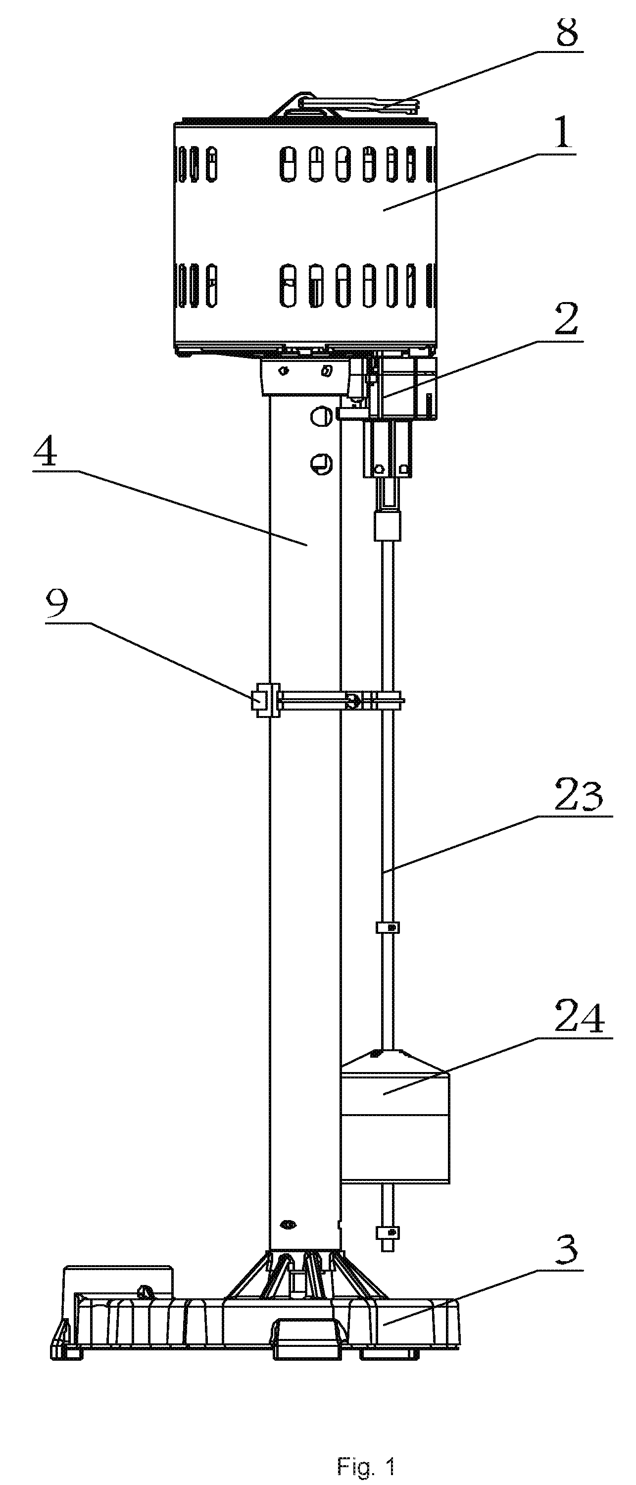
[0016] FIG. 1 is a schematic structural view of a preferred embodiment of the vertical-shaft sewage pump of the invention;
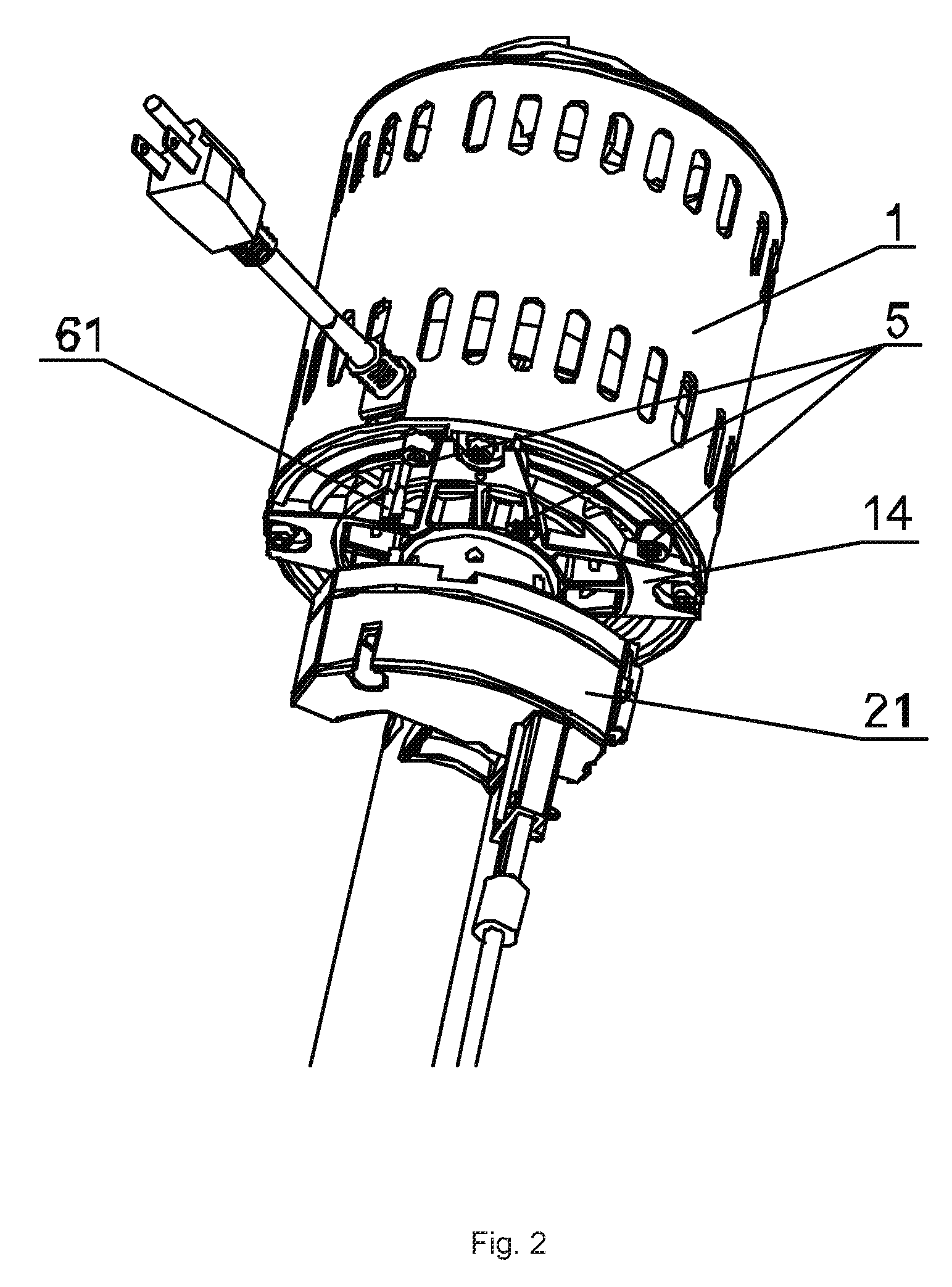
[0017] FIG. 2 is a schematic structural diagram of another preferred embodiment of the vertical-shaft sewage pump of the invention;
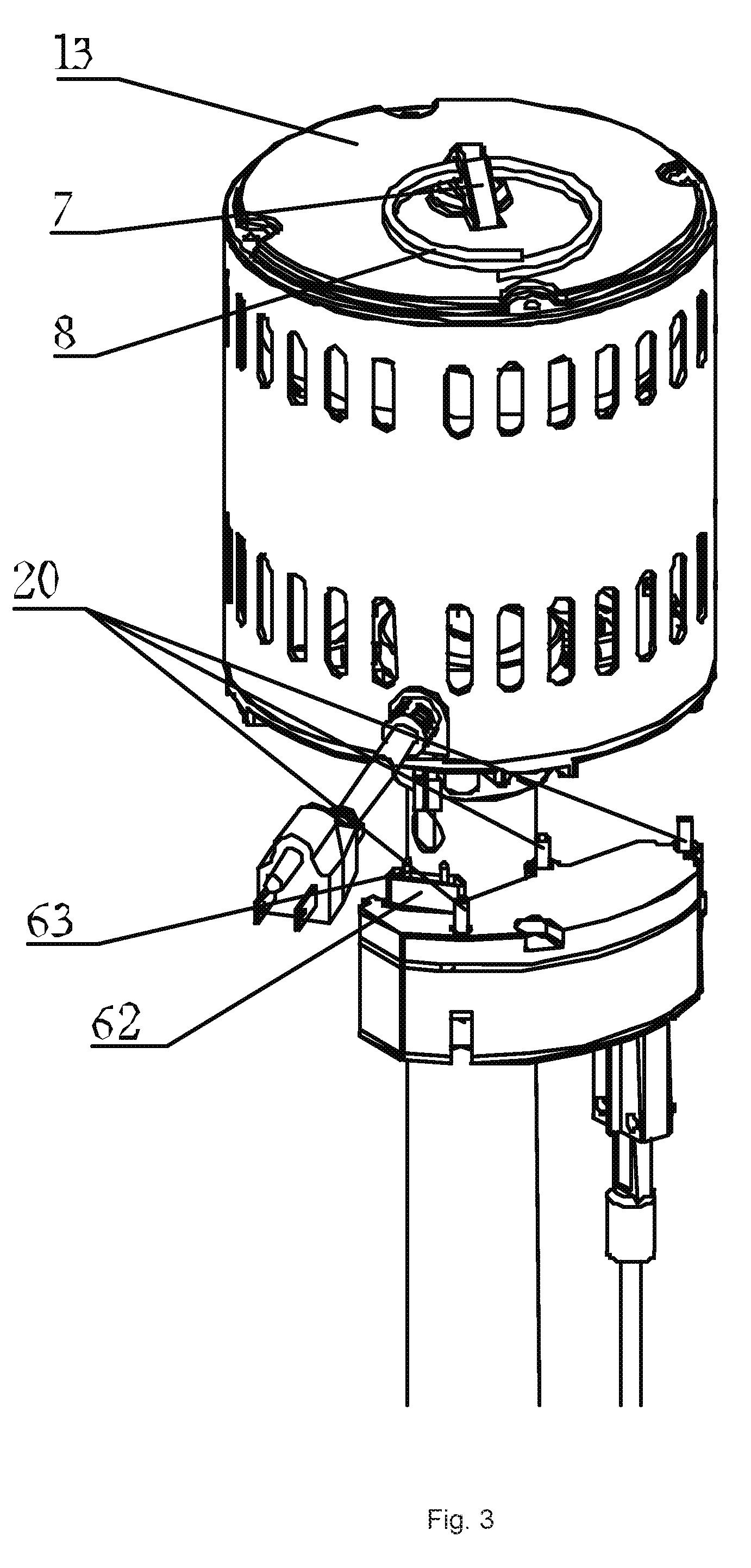
[0018] FIG. 3 is a schematic structural view of another preferred embodiment of the vertical-shaft sewage pump of the present invention;
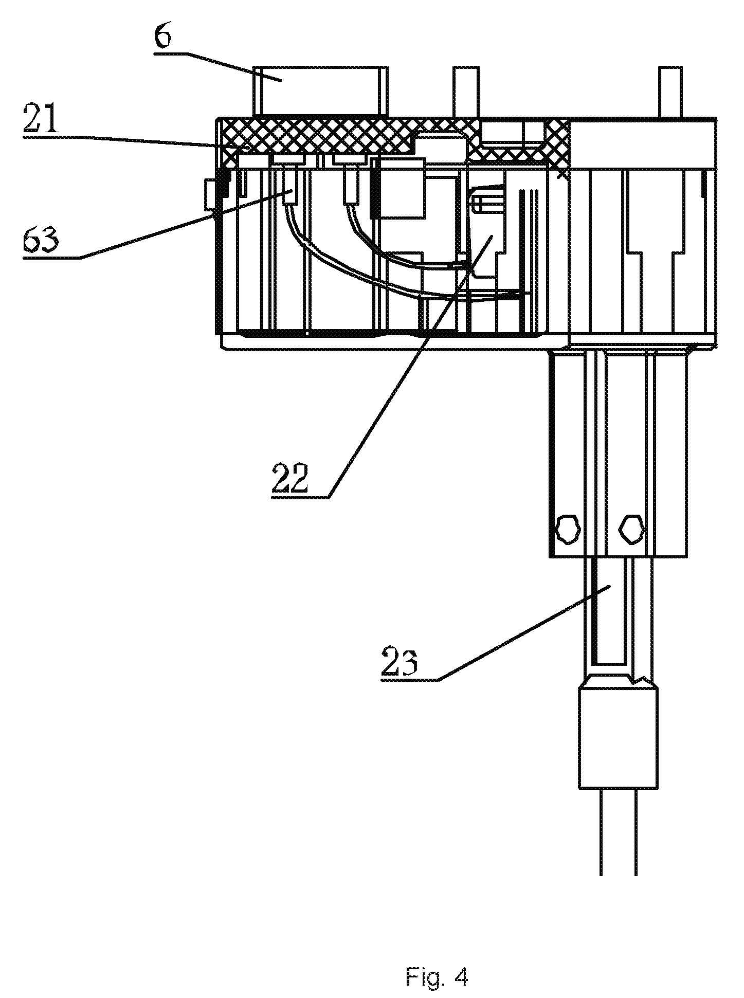
[0019] FIG. 4 is a schematic structural view of the inside of the control assembly of the vertical-shaft sewage pump switch of the present invention;
[0020] FIG. 5 is a schematic structural view of the bracket assembly of the vertical-shaft sewage pump according to the present invention.
DETAILED DESCRIPTION OF THE INVENTION
[0021] The following is clearly and completely describes of the technical solutions in the embodiments of the present invention. Apparently, the described embodiments are merely some but not all embodiments of the present invention. All other embodiments obtained by a person who is skilled in the art based on the embodiments of the present invention without creative efforts shall fall within the protection scope of the present invention.
[0022] Referring to FIGS. 1-5, embodiments of the present invention are set out as the following:
[0023] A vertical-shaft sewage pump with anti-collision switch includes a water pump driving component 1, a switch control component 2, a base 3 and a post 4 fixed on the base 3, the water pump driving assembly 1 includes a driving motor 11 and a casing 12 sleeved on the outside of the driving motor 11, an upper end cover 13 and a lower end cover 14 which respectively fixed at the upper end and the lower ends of the casing 12. A plurality of cylindrical bosses 5 is disposed on the lower surface of the lower end cover 14. The cylindrical bosses 5 are provided with internal threads. Screws 20 are provided at the corresponding positions of the upper surface of the switch box 21, and the switch control assembly 2 is installed to the lower side of the water pump drive assembly 1 via the screws 20 engaged with the internal threads provided on the cylindrical bosses 5. The switch control assembly 2 also includes a micro switch 22 housed inside the switch box 21, a guide rod 23 and a floating ball 24 which is movable up and down along the guide rod 23. A magnetic portion is provided at an end of the guide rod 23 that protrudes into one end of the switch box 21. The upper and lower sides of the floating ball on the guide rod 23 are respectively provided with an upper position limitation ring 25 and a lower position limitation ring 26. An electrical connection part 6 is disposed between the water pump drive assembly 1 and the switch controlling component 2. The electrical connection part 6 includes a tab 61 which electrically connected with the drive motor 11, a base 62 disposed on the upper surface of the switch box 21 and a pin 63 inserting in the base 62, the upper end of the pin 63 is connected with the tap 61, and the lower end is connected with the micro switch 22 in the water pump driving assembly via a wire.
[0024] Further, a convex plate 7 is outwardly extended from the upper surface of the upper end cover 13, a circular hole is provided on the convex plate 7, and the circular hole is penetrated with a hand ring 8. The handle ring 8 is not limited to a circle shape, a triangle shaped ring, or a square shaped ring, which is convenient for putting on and taking off during transportation and carrying are also applicable.
[0025] Further, the bracket assembly 9 includes a front bracket 91 and a rear bracket 92. The front bracket 91 and the rear bracket 92 are connected by screws at one ends, and the other ends of them are pivotally connected via a round pin extended in a through hole. To gain an anti-slip effort, the inner surface of the front bracket 91 and the rear bracket 92 is vertically provided with non-slip guiding grooves 93. A ring-shaped fixation ring 94 disposed on the end of the rear bracket 92 which is distant from the pillar 4. And the guide rod 23 is inserted into the fixation ring 94 and plays a fixation and supporting role therein.
[0026] During operation, when the water level rises and the float ball moves upwards, when the water reaches the upper water level, the float ball touches the upper limitation position circle and brings the guide rod to move upwards. The micro switch in the switch box is triggered to drive the motor to rotate and the water pump starts to work. When the water drops, the float ball moves downwards. When the water reaches the lower water level, the float ball touches the lower limitation circle and brings the guide rod to move upwards. The micro switch resets, the motor stops rotating, and the water pump stops working.
[0027] In summary, the vertical-shaft sewage pump with anti-collision switch of the present invention has a simple mechanism structure and it is easy to operate. The switch part and the pump body are integrally packaged, and the switch and the motor are connected in the form of pin-inserting, and the assembly structure is simplified. The integral structure is not easy to damage during transportation and has a wide application prospect.
[0028] The foregoing descriptions are merely embodiments of the present invention, and therefore do not mean to limit the scope of the present invention. Any implementation on the content of the present specification by using an alternative structure or equivalent process transformation, or, a direct or indirect application in the same field or in other related technical fields is in the protection scope of the present invention.
* * * * *
D00000
D00001
D00002
D00003
D00004
D00005
XML
uspto.report is an independent third-party trademark research tool that is not affiliated, endorsed, or sponsored by the United States Patent and Trademark Office (USPTO) or any other governmental organization. The information provided by uspto.report is based on publicly available data at the time of writing and is intended for informational purposes only.
While we strive to provide accurate and up-to-date information, we do not guarantee the accuracy, completeness, reliability, or suitability of the information displayed on this site. The use of this site is at your own risk. Any reliance you place on such information is therefore strictly at your own risk.
All official trademark data, including owner information, should be verified by visiting the official USPTO website at www.uspto.gov. This site is not intended to replace professional legal advice and should not be used as a substitute for consulting with a legal professional who is knowledgeable about trademark law.