Semi-Hermetic Refrigerant Compressor
Grosse-Kracht; Rainer ; et al.
U.S. patent application number 16/376430 was filed with the patent office on 2019-08-01 for semi-hermetic refrigerant compressor. The applicant listed for this patent is BITZER Kuehlmaschinenbau GmbH. Invention is credited to Rainer Grosse-Kracht, Jens Mannewitz, Eduardo Martin, Hermann Renz.
| Application Number | 20190234392 16/376430 |
| Document ID | / |
| Family ID | 57104046 |
| Filed Date | 2019-08-01 |


View All Diagrams
| United States Patent Application | 20190234392 |
| Kind Code | A1 |
| Grosse-Kracht; Rainer ; et al. | August 1, 2019 |
Semi-Hermetic Refrigerant Compressor
Abstract
In order to improve a semi-hermetic refrigerant compressor, comprising a reciprocating piston compressor, an electric motor, an overall housing which has a motor housing portion for the electric motor and a compressor housing portion for the reciprocating piston compressor, a suction-side refrigerant path which leads from a suction connection on the overall housing to an inlet chamber of the reciprocating piston compressor, and a pressure-side refrigerant path which leads from an outlet chamber of the reciprocating piston compressor to a pressure connection on the overall housing, such that the refrigerant compressor functions more efficiently, it is proposed that the electric motor is configured as a synchronous motor, in the rotor of which there are arranged permanent magnets for the synchronous operation of the electric motor and a squirrel cage for starting up the electric motor in asynchronous operation.
| Inventors: | Grosse-Kracht; Rainer; (Sindelfingen, DE) ; Renz; Hermann; (Egenhausen, DE) ; Martin; Eduardo; (Leipzig, DE) ; Mannewitz; Jens; (Schkeuditz, DE) | ||||||||||
| Applicant: |
|
||||||||||
|---|---|---|---|---|---|---|---|---|---|---|---|
| Family ID: | 57104046 | ||||||||||
| Appl. No.: | 16/376430 | ||||||||||
| Filed: | April 5, 2019 |
Related U.S. Patent Documents
| Application Number | Filing Date | Patent Number | ||
|---|---|---|---|---|
| PCT/EP2016/074063 | Oct 7, 2016 | |||
| 16376430 | ||||
| Current U.S. Class: | 1/1 |
| Current CPC Class: | F04B 39/121 20130101; F04B 49/24 20130101; F04B 35/01 20130101; F04B 27/053 20130101; F04B 7/0076 20130101; F04B 35/04 20130101; F04B 39/123 20130101; F04B 39/125 20130101; F04B 49/06 20130101 |
| International Class: | F04B 39/12 20060101 F04B039/12; F04B 35/04 20060101 F04B035/04; F04B 7/00 20060101 F04B007/00 |
Claims
1. A semi-hermetic refrigerant compressor, comprising a reciprocating piston compressor and an electric motor, an overall housing which has a motor housing portion for the electric motor and a compressor housing portion for the reciprocating piston compressor, a suction-side refrigerant path which leads from a suction connection on the overall housing to an inlet chamber of the reciprocating piston compressor, and a pressure-side refrigerant path which leads from an outlet chamber of the reciprocating piston compressor to a pressure connection on the overall housing, wherein at least one cylinder of the reciprocating piston compressor is provided in the compressor housing portion and has a piston movable in a cylinder bore formed in the compressor housing portion, a valve plate closing the cylinder bore, and a cylinder head extending over the valve plate and forming part of the compressor housing portion, the electric motor is configured as a synchronous motor, in the rotor of which there are arranged permanent magnets for the synchronous operation of the electric motor and a squirrel cage for the start-up of the electric motor in asynchronous operation.
2. A refrigerant compressor according to claim 1, wherein the permanent magnets extend parallel to a rotor axis of the rotor.
3. A refrigerant compressor according to claim 2, wherein the permanent magnets are formed as planar bodies, the flat sides of which extend in a longitudinal direction and in a transverse direction running transversely to the longitudinal direction.
4. A refrigerant compressor according to claim 1, wherein the permanent magnets each extend with their longitudinal direction parallel to the rotor axis.
5. A refrigerant compressor according to claim 1, wherein the permanent magnets extend with their transverse directions along outer edges of a geometric rectangle that is symmetrical with respect to the rotor axis.
6. A refrigerant compressor according to claim 1, wherein the permanent magnets formed as planar bodies have a different magnetic polarity (N, S) on their mutually opposite flat sides, one of which faces towards the rotor axis and the other of which faces away from the rotor axis.
7. A refrigerant compressor according to claim 1, wherein the suction-side refrigerant path passes through the motor housing for cooling of the electric motor.
8. A semi-hermetic refrigerant compressor, comprising a reciprocating piston compressor and an electric motor, an overall housing which has a motor housing portion for the electric motor and a compressor housing portion for the reciprocating piston compressor, a suction-side refrigerant path which leads from a suction connection on the overall housing to an inlet chamber of the reciprocating piston compressor, and a pressure-side refrigerant path which leads from an outlet chamber of the reciprocating piston compressor to a pressure connection on the overall housing, wherein at least one cylinder of the reciprocating piston compressor is provided in the compressor housing portion and has a piston movable in a cylinder bore formed in the compressor housing portion, a valve plate closing the cylinder bore, and a cylinder head extending over the valve plate and forming part of the compressor housing portion, the refrigerant compressor is provided with an externally controlled mechanical capacity control unit.
9. A semi-hermetic refrigerant compressor, comprising a reciprocating piston compressor and an electric motor, an overall housing which has a motor housing portion for the electric motor and a compressor housing portion for the reciprocating piston compressor, a suction-side refrigerant path which leads from a suction connection on the overall housing to an inlet chamber of the reciprocating piston compressor, and a pressure-side refrigerant path which leads from an outlet chamber of the reciprocating piston compressor to a pressure connection on the overall housing, wherein at least one cylinder of the reciprocating piston compressor is provided in the compressor housing portion and has a piston movable in a cylinder bore formed in the compressor housing portion, a valve plate closing the cylinder bore, and a cylinder head extending over the valve plate and forming part of the compressor housing portion, the mechanical capacity control unit for capacity reduction in at least one cylinder connects the outlet-side refrigerant path to the inlet-side refrigerant path.
10. A refrigerant compressor according to claim 9, wherein the mechanical capacity control unit is arranged on the at least one cylinder head.
11. A refrigerant compressor according to claim 10, wherein the mechanical capacity control unit is at least partially integrated in the at least one cylinder head.
12. A refrigerant compressor according to claim 9, wherein the mechanical capacity control unit, for capacity reduction, connects an outlet chamber in the cylinder head to an inlet chamber in the cylinder head by means of a connection channel.
13. A refrigerant compressor according to claim 12, wherein the connection channel is arranged integrated in the cylinder head.
14. A refrigerant compressor according to claim 1, wherein the outlet chamber is arranged in the cylinder head directly adjacently to at least one outlet opening for the corresponding cylinder in the valve plate.
15. A refrigerant compressor according to claim 1, wherein the inlet chamber is arranged in the cylinder head directly adjacently to an inlet opening for the corresponding cylinder in the valve plate.
16. A refrigerant compressor according to claim 9, wherein the mechanical capacity control unit has a sealing piston for closing the connection channel.
17. A refrigerant compressor according to claim 16, wherein the sealing piston, in order to close the connection channel, is placeable against a seal seat, which runs around the connection channel peripherally.
18. A refrigerant compressor according to claim 16, wherein a seal region of the sealing piston is made of a metal having a lower hardness than a metal from which the seal seat is made.
19. A refrigerant compressor according to claim 17, wherein the seal seat is arranged in a wall portion of the cylinder head separating the inlet chamber from the outlet chamber.
20. A refrigerant compressor according to claim 17, wherein the seal seat is arranged in a wall portion running above the valve plate and above the inlet chamber.
21. A refrigerant compressor according to claim 17, wherein the seal seat is arranged on the side of the inlet chamber opposite the valve plate.
22. A refrigerant compressor according to claim 17, wherein starting from the seal seat, the stroke of the sealing piston ranges from a quarter to half of the mean diameter of the connection channel.
23. A refrigerant compressor according to claim 1, wherein a cylinder head has an inlet chamber and an outlet chamber for a cylinder bank comprising at least two cylinders.
24. A refrigerant compressor according to claim 1, wherein the mechanical capacity control unit is associated with a cylinder bank.
25. A refrigerant compressor according to claim 23, wherein in the case of N cylinder banks of the refrigerant compressor a mechanical capacity control unit is associated with at least N-1 cylinder bank(s).
26. A refrigerant compressor according to claim 23, wherein a mechanical capacity control unit is associated with each cylinder bank.
27. A refrigerant compressor according to claim 1, wherein a check valve is provided in the compressor housing portion following on from the refrigerant paths that can be influenced by the mechanical capacity control unit.
28. A refrigerant compressor according to claim 27, wherein the check valve has an outlet opening provided in the valve plate and a valve element cooperating with the valve plate.
29. A refrigerant compressor according to claim 28, wherein the valve element is held on the valve plate.
30. A refrigerant compressor according to claim 16, wherein the sealing piston in the direction of its position cooperating with the seal seat is acted on by a compression spring.
31. A refrigerant compressor according to claim 16, wherein the sealing piston is actuable by a pressure chamber, which is actable on either by suction pressure or by high pressure depending on the external control of the capacity control unit.
32. A refrigerant compressor according to claim 31, wherein the pressure chamber in the open position of the sealing piston has a volume that is less than a third, better still less than a quarter of the maximum volume of the pressure chamber in the closed position.
33. A refrigerant compressor according to claim 8, wherein a control unit comprised by the capacity control unit is provided and is usable to control the pressure applied to the sealing piston.
34. A refrigerant compressor according to claim 8, wherein a capacity controller is provided and controls the at least one mechanical capacity control unit in accordance with a required compressor delivery capacity.
35. A refrigerant compressor according to claim 1, wherein a start-up control unit is provided and controls the start-up of the electric motor.
36. A refrigerant compressor according to claim 35, wherein the start-up control unit operates the electric motor to start up with the windings connected in a manner reducing the start-up current.
37. A refrigerant compressor according to claim 35, wherein the start-up control unit in order to start up the electric motor initially energizes a first part-winding and then energizes a second part-winding in a stator of the electric motor.
38. A refrigerant compressor according to claim 35, wherein the start-up control unit controls the capacity controller at the start-up of the electric motor such that the reciprocating piston compressor operates only with reduced compressor delivery capacity at the start-up of the electric motor.
39. A refrigerant compressor according to claim 38, wherein the start-up control unit controls the capacity controller in such a way that the reciprocating piston compressor works with the smallest possible compressor delivery capacity at the start-up of the electric motor.
40. A refrigerant compressor according to claim 1, wherein the reciprocating piston compressor works with a suction pressure ranging from 10 bar to 50 bar.
41. A refrigerant compressor according to claim 1, wherein the reciprocating piston compressor works with a high pressure ranging from 40 to 160 bar.
42. A refrigerant compressor according to claim 1, wherein the reciprocating piston compressor works with carbon dioxide as refrigerant and in particular is configured for operation with carbon dioxide as refrigerant.
Description
CROSS-REFERENCE TO RELATED PATENT APPLICATION
[0001] This application is a continuation of International application number PCT/EP2016/074063 filed on Oct. 7, 2016.
[0002] This patent application claims the benefit of International application No. PCT/EP2016/074063 of Oct. 7, 2016 the teachings and disclosure of which are hereby incorporated in their entirety by reference thereto.
BACKGROUND OF THE INVENTION
[0003] The invention relates to a semi-hermetic refrigerant compressor, comprising a reciprocating piston compressor and an electric motor, an overall housing which has a motor housing portion for the electric motor and a compressor housing portion for the reciprocating piston compressor, a suction-side refrigerant path which leads from a suction connection on the overall housing to an inlet chamber of the reciprocating piston compressor, and a pressure-side refrigerant path which leads from an outlet chamber of the reciprocating piston compressor to a pressure connection on the overall housing, wherein at least one cylinder of the reciprocating piston compressor is provided in the compressor housing portion and has a piston movable in a cylinder bore formed in the compressor housing portion, a valve plate closing the cylinder bore, and a cylinder head extending over the valve plate and forming part of the compressor housing portion.
[0004] Semi-hermetic refrigerant compressors of this kind are known from the prior art.
[0005] A semi-hermetic refrigerant compressor comprises the overall housing as outer housing, wherein in particular the electric motor is arranged in a refrigerant atmosphere. A semi-hermetic refrigerant compressor is not provided with an outer encapsulation fully enclosing the reciprocating piston compressor and the electric motor jointly, but instead the compressor housing forming the at least one cylinder housing constitutes the outer housing.
[0006] The problem exists of operating these compressors energy-efficiently.
SUMMARY OF THE INVENTION
[0007] In accordance with the invention this problem is solved in a semi-hermetic refrigerant compressor of the kind described in the introduction in that the electric motor is designed as a synchronous motor, in the rotor of which there are arranged permanent magnets for the synchronous operation of the electric motor and a squirrel cage for start-up of the electric motor in asynchronous operation.
[0008] The advantage of the solution according to the invention can be considered the fact that an electric motor of this kind for driving a semi-hermetic refrigerant compressor has a higher energy efficiency, in particular under full load and also under partial load. A further advantage of an electric motor of this kind can be considered the fact that the delivery volume is constant by means of the synchronous operation, even in the high-load range.
[0009] No further details have yet been provided in respect of the configuration of the permanent magnets.
[0010] An advantageous solution provides that the permanent magnets extend parallel to a rotor axis of the rotor.
[0011] It is also preferably provided that the permanent magnets are formed as planar bodies, the flat sides of which extend in a longitudinal direction and in a transverse direction running transversely to the longitudinal direction.
[0012] The permanent magnets in this case are expediently arranged in the rotor such that they each extend with their longitudinal direction parallel to the rotor axis.
[0013] The permanent magnets are also preferably arranged in the rotor such that they extend with their transverse directions along outer edges of a geometric rectangle that is symmetrical with respect to the rotor axis.
[0014] Also, no further details have yet been provided in respect of the magnetization of the permanent magnets.
[0015] An advantageous solution provides that the permanent magnets configured as planar bodies have a different magnetic polarity on their mutually opposite flat sides, one of which faces towards the rotor axis and the other of which faces away from the rotor axis, such that planar magnetic poles are thus available in the rotor in a simple way for the synchronous operation of the electric motor.
[0016] In principle, the electric motor can be cooled in a wide range of ways.
[0017] An advantageous solution provides that the suction-side refrigerant path passes through the motor housing for cooling of the electric motor.
[0018] Furthermore, alternatively or additionally to the previously described features of the semi-hermetic refrigerant compressor, a further solution according to the invention provides that the refrigerant compressor is provided with a mechanical externally controllable or controlled capacity control unit.
[0019] An externally controlled capacity control unit of this kind creates the possibility of controlling the compressor delivery capacity of the semi-hermetic refrigerant compressor without a frequency converter for the electric motor by means of the mechanical capacity control unit, which is cost-effective and efficient, and additionally in particular opens up the possibility of reducing the mechanical loads on the reciprocating piston compressor.
[0020] In particular, it is provided here that the mechanical capacity control unit for capacity reduction in at least one cylinder connects the outlet-side refrigerant path to the inlet-side refrigerant path. This creates the possibility of operating the at least one cylinder such that it does not contribute to the compressor delivery capacity.
[0021] This solution has the advantage that, when implementing a capacity reduction, the mechanical load on the components of the reciprocating piston compressor is thus low, since the refrigerant is at a pressure level close to the inlet side and flows back from the outlet side to the inlet side, wherein this is not accompanied by any great pressure fluctuations or even pressure peaks or temperature peaks in the reciprocating piston compressor, which in particular also reduce the efficiency in the event of capacity reduction.
[0022] A wide range of different possible solutions are conceivable in respect of the arrangement of the mechanical capacity control unit.
[0023] In accordance with an advantageous solution, the mechanical capacity control unit is arranged on the cylinder head, thus resulting in the advantage that the mechanical capacity control unit can thus cooperate easily with at least one of the cylinders.
[0024] It is particularly favorable if the mechanical capacity control unit is at least partially integrated in the at least one cylinder head.
[0025] In order to be able to cooperate as optimally as possible with at least one cylinder, it is preferably provided that the mechanical capacity control unit, for capacity reduction, connects an outlet chamber in the cylinder head to an inlet chamber in the cylinder head by means of a connection channel.
[0026] A direct cooperation of the capacity control unit with the at least one cylinder associated with the cylinder head is thus possible, such that a compact design of the refrigerant compressor thus can be realized in the case of a capacity control unit incorporated in this way.
[0027] It is particularly expedient if the connection channel is arranged integrated in the cylinder head, such that likewise the spatial requirement for the cooperation of the capacity control unit with the inlet chamber and the outlet chamber thus can be optimized.
[0028] In particular is provided that the outlet chamber is arranged in the cylinder head directly adjacently to at least one outlet opening for the corresponding cylinder in the valve plate, and therefore in particular the outlet chamber is also directly adjacently to the valve plate and the outlet opening, in particular with the outlet valve.
[0029] It is also preferably provided that the inlet chamber in the cylinder head is arranged directly adjacently to an inlet opening for the corresponding cylinder in the valve plate, such that the inlet chamber is also directly adjacently to the valve plate and the inlet opening.
[0030] A wide range of possibilities are conceivable with regard to the way in which the mechanical capacity control unit opens or closes the connection channel between the outlet chamber and the inlet chamber.
[0031] For example, it would be conceivable to use conventional gate designs.
[0032] A particularly advantageous solution provides that the mechanical capacity control unit has a sealing piston for closing the connection channel.
[0033] A sealing piston of this kind creates the possibility of opening or closing the connection channel in particular with the shortest response time possible.
[0034] In order to provide a reliable seal the sealing piston is preferably guided in a guide bore, in particular in the cylinder head, in a manner sealed by means of a piston ring.
[0035] In particular, it is provided that the sealing piston, in order to close the connection channel, is placeable against a seal seat, which runs around the connection channel peripherally, such that the connection channel is interrupted when the sealing piston is placed against the seal seat, whereas the connection channel is opened again when the sealing piston is lifted from the seal seat.
[0036] In order to achieve reliable closure durably, it is preferably provided that a seal region of the sealing piston, which seal region can be placed against the seal seat, is made of a metal having a lower hardness than a metal from which the seal seat is made, or vice versa.
[0037] The seal seat can be arranged in a wide range of different ways.
[0038] A particularly advantageous and compact solution provides that the seal seat is arranged on a wall portion of the cylinder head separating the inlet chamber from the outlet chamber.
[0039] Here, either the seal seat can be formed as part of the wall portion or the seal seat is formed by a component inserted into the wall portion of the cylinder head.
[0040] The seal seat is preferably arranged such that it is arranged in a wall portion running above the valve plate and above the inlet chamber, and therefore in particular the seal seat at the same time constitutes an inlet opening, opposite the valve plate, for the inlet chamber.
[0041] It is also furthermore preferably provided that the seal seat at the same time constitutes an outlet opening for the outlet chamber, such that a direct transition from the outlet chamber into the inlet chamber is realized by the seal seat.
[0042] For a spatial compact assembly, it has proven to be particularly favorable if the seal seat is arranged on a side of the inlet chamber opposite the valve plate.
[0043] A rapid change of the sealing piston between the closed position and the open position is possible preferably if, starting from the seal seat, the stroke of the sealing piston ranges from a quarter to half of the mean diameter of the connection channel.
[0044] No further details have been provided with the explanation of the individual embodiments provided thus far in respect of the association of the mechanical capacity control unit with individual cylinders.
[0045] One solution provides that the mechanical capacity control unit is associated with one cylinder and if a plurality of cylinders is provided then a plurality of mechanical capacity control units is provided, wherein it is not absolutely necessary for a mechanical capacity control unit to be associated with each cylinder.
[0046] A favorable solution provides that a cylinder head has an inlet chamber and an outlet chamber for a cylinder bank comprising at least two cylinders.
[0047] In this case, a plurality of cylinders is therefore combined to form a cylinder bank.
[0048] In a solution of this kind it is advantageously provided that the mechanical capacity control unit is associated with a cylinder bank, in particular comprising at least two cylinders.
[0049] In the case of a refrigerant compressor comprising a plurality of cylinder banks, for example N cylinder banks, it is preferably provided that a mechanical capacity control unit is associated with at least N-1 cylinder bank(s).
[0050] However, in order to reduce the capacity of the refrigerant compressor optimally, it is preferably provided that a mechanical capacity control unit is associated with each cylinder bank.
[0051] In order to avoid a backflow of highly pressurized refrigerant and therefore a pressure drop at the outlet connection element during a capacity reduction, a check valve is provided in the compressor housing portion following on from the refrigerant paths that can be influenced by the mechanical capacity control unit.
[0052] It is also preferably provided that the check valve has an outlet opening provided in the valve plate and a valve element cooperating with the valve plate, such that the valve plate can be used also for the arrangement and forming of the check valve.
[0053] In particular it is provided that the valve element is held on the valve plate such that the valve plate is used not only to form the inlet and outlet valves, but also to hold the valve element of the check valve.
[0054] No further details have been provided in conjunction with the explanation of the individual exemplary embodiments provided thus far in respect of the control of the sealing piston.
[0055] An advantageous solution thus provides that the sealing piston, in the direction of its position cooperating with the seal seat, is acted on by a compression spring such that the compression spring ensures that the sealing piston in the non-working state of the refrigerant compressor closes the connection channel on account of the effect of the compression spring.
[0056] It is also preferably provided that the sealing piston can be controlled by a pressure chamber, which can be acted on either by suction pressure or by high pressure depending on the external control of the capacity control unit, wherein, in the event that the pressure chamber is acted on by suction pressure, the sealing piston transitions into its open position, and, in the event that the pressure chamber is acted on by high pressure, the sealing piston is acted on in the direction of its closed position, additionally to the effect of the compression spring.
[0057] The volume of the pressure chamber is in particular so low that, in the open position of the sealing piston, it is less than a third, better still less than a quarter, even better still less than a fifth, more advantageously less than a sixth, and particularly advantageously less than a seventh, and even more advantageously less than an eighth of the maximum volume of the pressure chamber in the closed position of the sealing piston.
[0058] This dimension of the pressure chamber makes it possible to change quickly between the closed position and the open position, since the pressure must be changed between suction pressure and high pressure only in a small volume.
[0059] A control unit comprised by the capacity control unit is preferably provided in order to act on the pressure chamber with high pressure or suction pressure and can be used to control the pressure applied to the sealing piston.
[0060] In order to execute this capacity control of the refrigerant compressor, a capacity controller is preferably provided which controls the at least one capacity control unit in accordance with a required compressor delivery capacity.
[0061] The capacity controller is in particular connected to a higher level system controller and receives information from the system controller regarding the required compressor delivery capacity.
[0062] The capacity controller then controls the at least one or more capacity control units on the basis of this information regarding the required compressor delivery capacity, such that the refrigerant compressor provides the required compressor delivery capacity but does not provide an unnecessarily high compressor delivery capacity.
[0063] To this end, the refrigerant compressor is designed such that the maximum compressor delivery capacity thereof is sufficient for the maximum compressor delivery capacity required by the system controller, and lower compressor delivery capacities are achieved by capacity reduction by means of the at least one capacity control unit.
[0064] In addition, a start-up control unit is preferably provided for the refrigerant compressor, in particular the refrigerant compressor is provided with a start-up control unit which controls the start-up of the electric motor, which in the solution according to the invention starts up as an asynchronous motor until it has reached the synchronous speed, and then runs as a synchronous motor.
[0065] The start-up control unit can control the operation of the refrigerant compressor differently so as to allow the electric motor to start up suitably.
[0066] In particular, the start-up control unit works such that it operates the electric motor to start up with the windings connected in a manner reducing the start-up current.
[0067] This could be realized for example by a switchover from a star connection for start-up into a delta connection after start-up.
[0068] An advantageous solution provides that the start-up control unit, to start up the electric motor, firstly energizes a first part-winding and then energizes a second part-winding in a stator of the electric motor.
[0069] The start-up of the electric motor with a first part-winding has the advantage that it is thus possible to reduce the start-up current and therefore for example to avoid a heavy loading of the electrical supply network caused by an excessively high start-up current.
[0070] Alternatively or additionally the start-up control unit is configured such that it controls the capacity controller during the start-up of the electric motor such that the reciprocating piston compressor works only with reduced compressor delivery capacity at the time of start-up of the electric motor.
[0071] It is particularly favorable for the start-up of the electric motor if the start-up controller controls the capacity controller in such a way that the reciprocating piston compressor works with the smallest possible compressor delivery capacity at the time of start-up of the electric motor.
[0072] The smallest possible compressor delivery capacity may be a compressor delivery capacity at which one or more cylinders are still operating.
[0073] A particularly favorable embodiment provides that the capacity of the reciprocating piston compressor can be controlled in such a way that at the smallest possible compressor delivery capacity none of the cylinders compress refrigerant, such that the torque necessary to start up the reciprocating piston compressor is thus minimal.
[0074] In addition, an advantageous solution provides that the start-up controller controls the capacity controller in such a way that, once synchronous operation of the electric motor has been reached, the compressor delivery capacity is increased in steps, for example with the additional connection of a further cylinder or a further cylinder bank or optionally successive additional connection of further cylinders or further cylinder banks.
[0075] No further details have been provided in conjunction with the solution according to the invention in respect of the operating states of the reciprocating piston compressor.
[0076] In principle, the reciprocating piston compressor according to the invention can operate with all refrigerants usual for semi-hermetic refrigerant compressors.
[0077] However, the solution according to the invention creates particular advantages for the operation of the reciprocating piston compressor, in particular for damage-free operation of the reciprocating piston compressor when the reciprocating piston compressor works with a suction pressure ranging from 10 bar to 50 bar.
[0078] The solution according to the invention is also particularly advantageous in respect of the mechanical loading of the reciprocating piston compressor if the reciprocating piston compressor works with a high pressure ranging from 40 bar to 16.sub.0 bar.
[0079] In particular, the refrigerant compressor according to the invention can be used particularly advantageously if the reciprocating piston compressor works with carbon dioxide as refrigerant and in particular is configured for operation with carbon dioxide as refrigerant.
[0080] Further features and advantages of the invention are the subject of the following description and the drawings of several exemplary embodiments.
BRIEF DESCRIPTION OF THE DRAWINGS
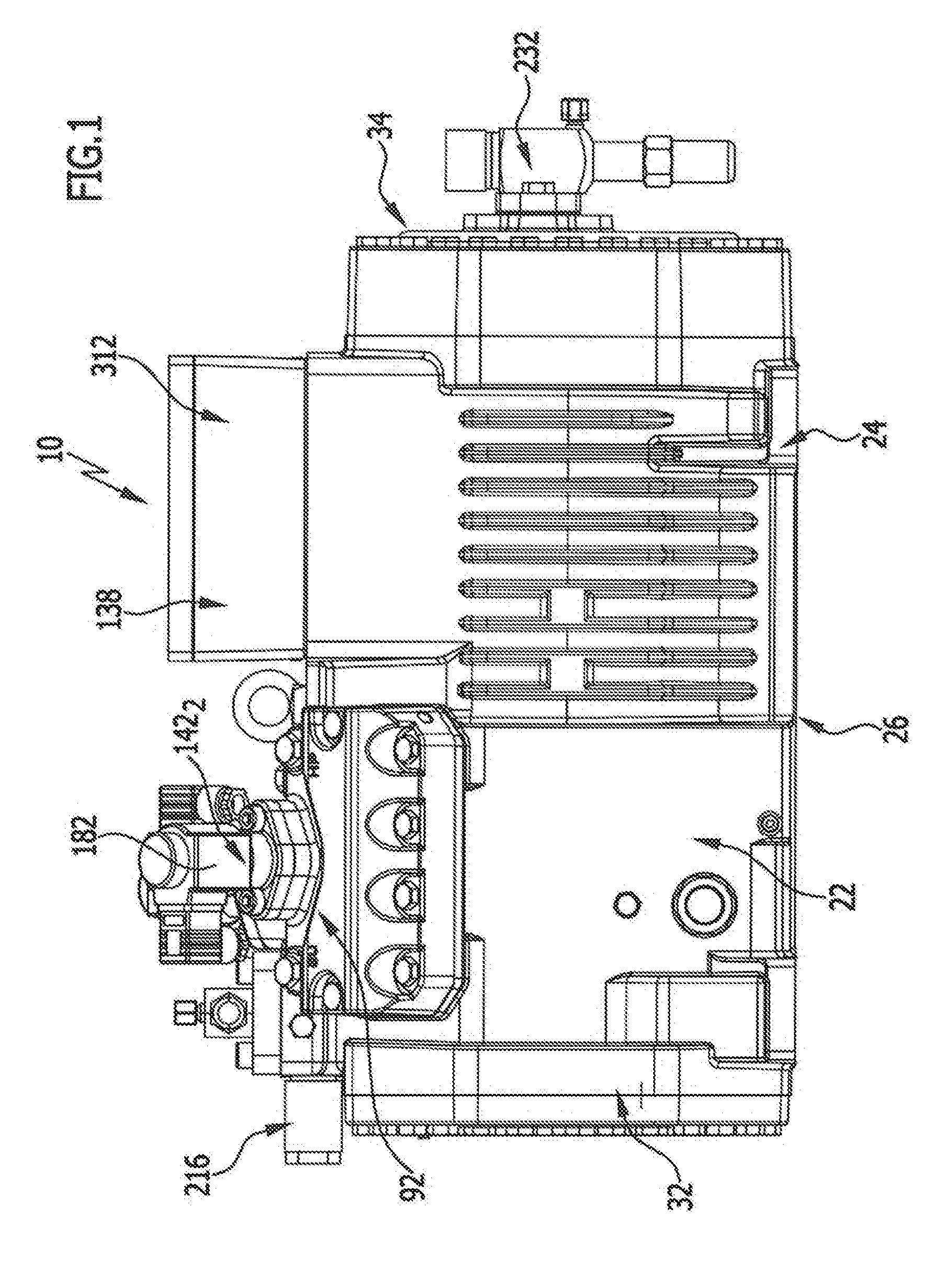
[0081] FIG. 1 shows a side view of an exemplary embodiment of a refrigerant compressor according to the invention;
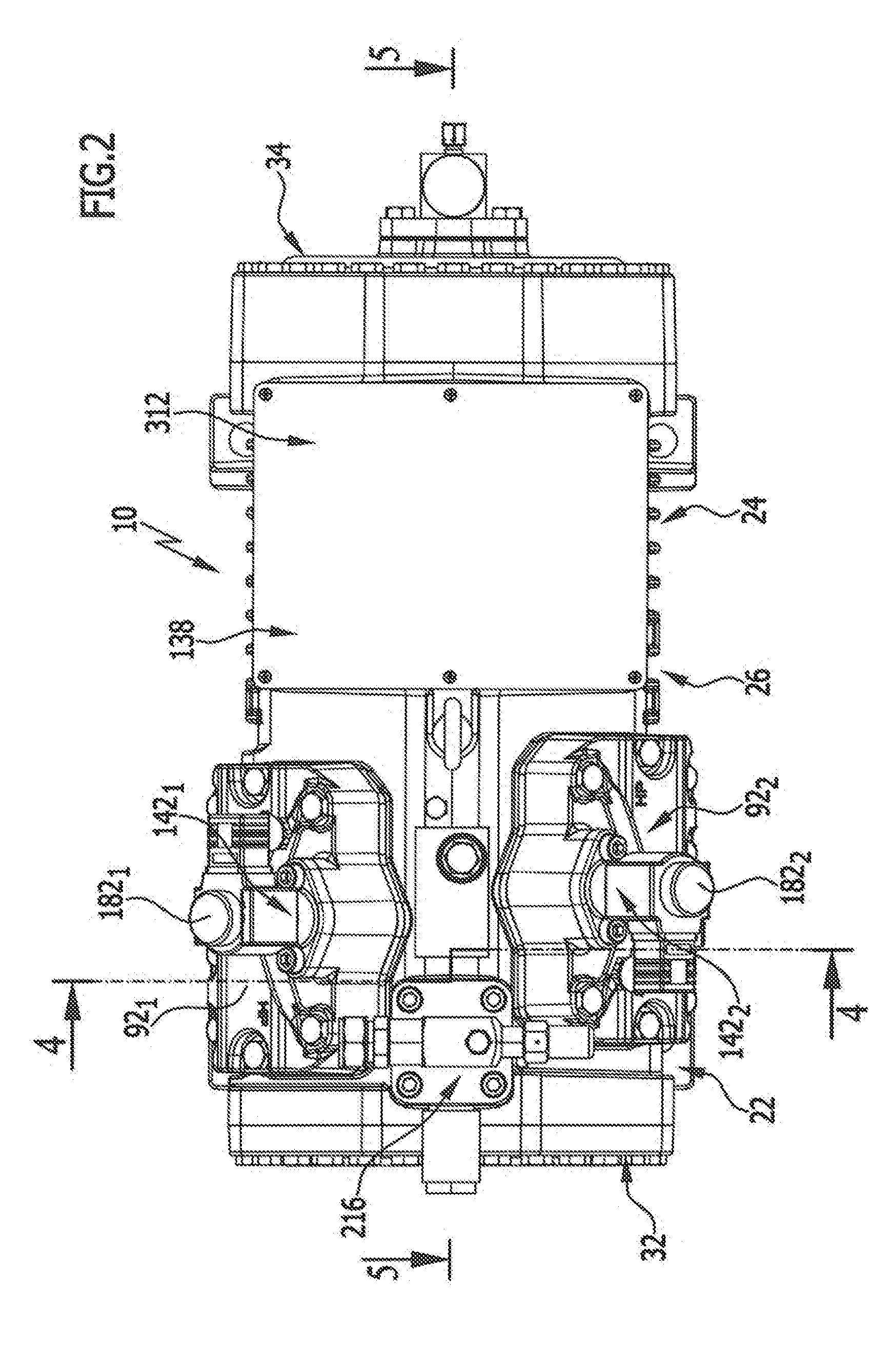
[0082] FIG. 2 shows a plan view in the direction of the arrow A in FIG. 1 of the refrigerant compressor according to the invention;
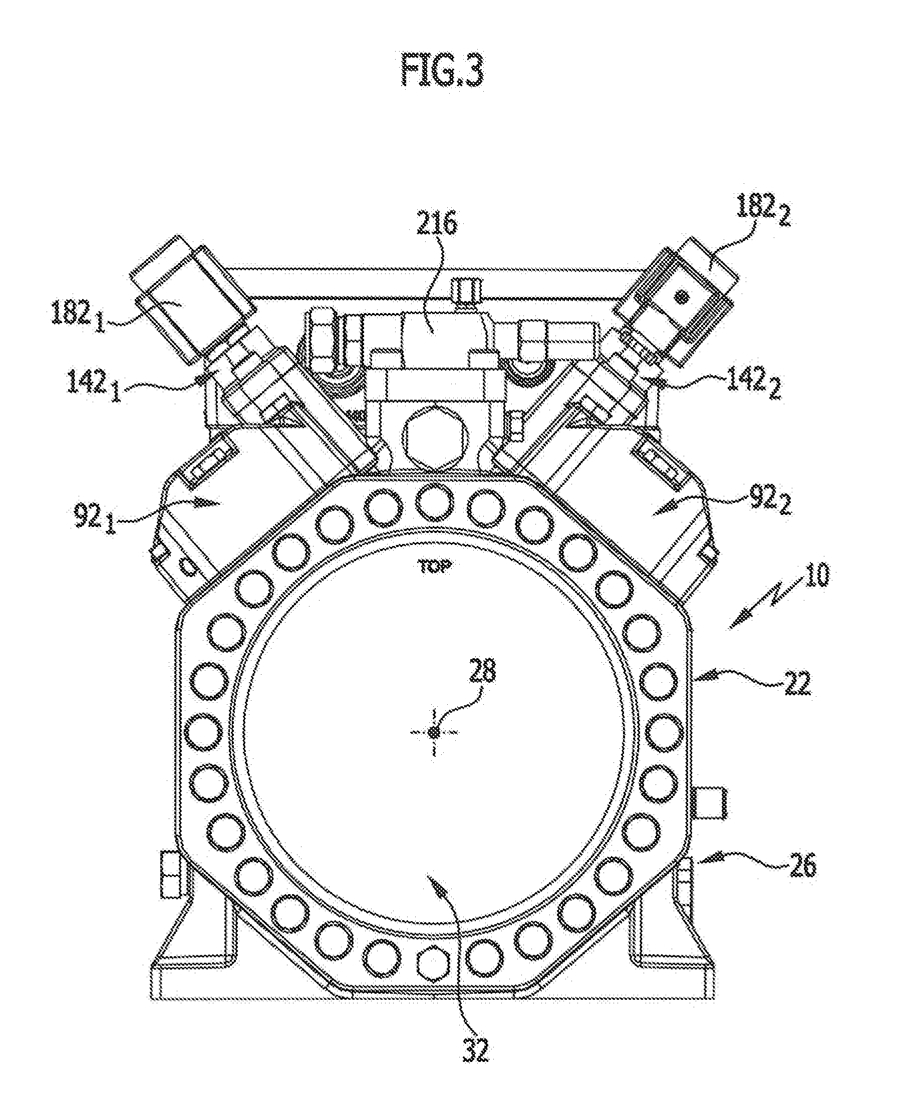
[0083] FIG. 3 shows a front view of the exemplary embodiment of the refrigerant compressor according to the invention;
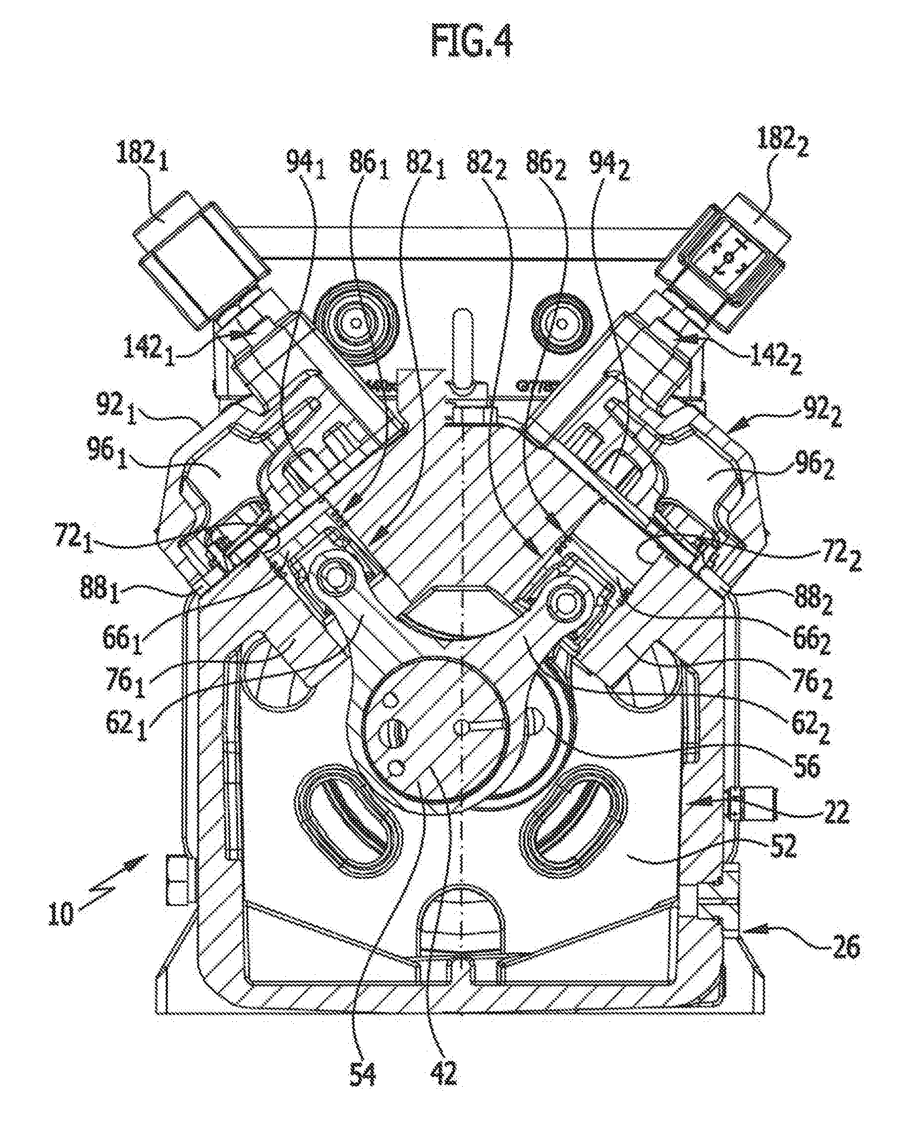
[0084] FIG. 4 shows a section, offset to one side, along line 4-4 in FIG. 2;
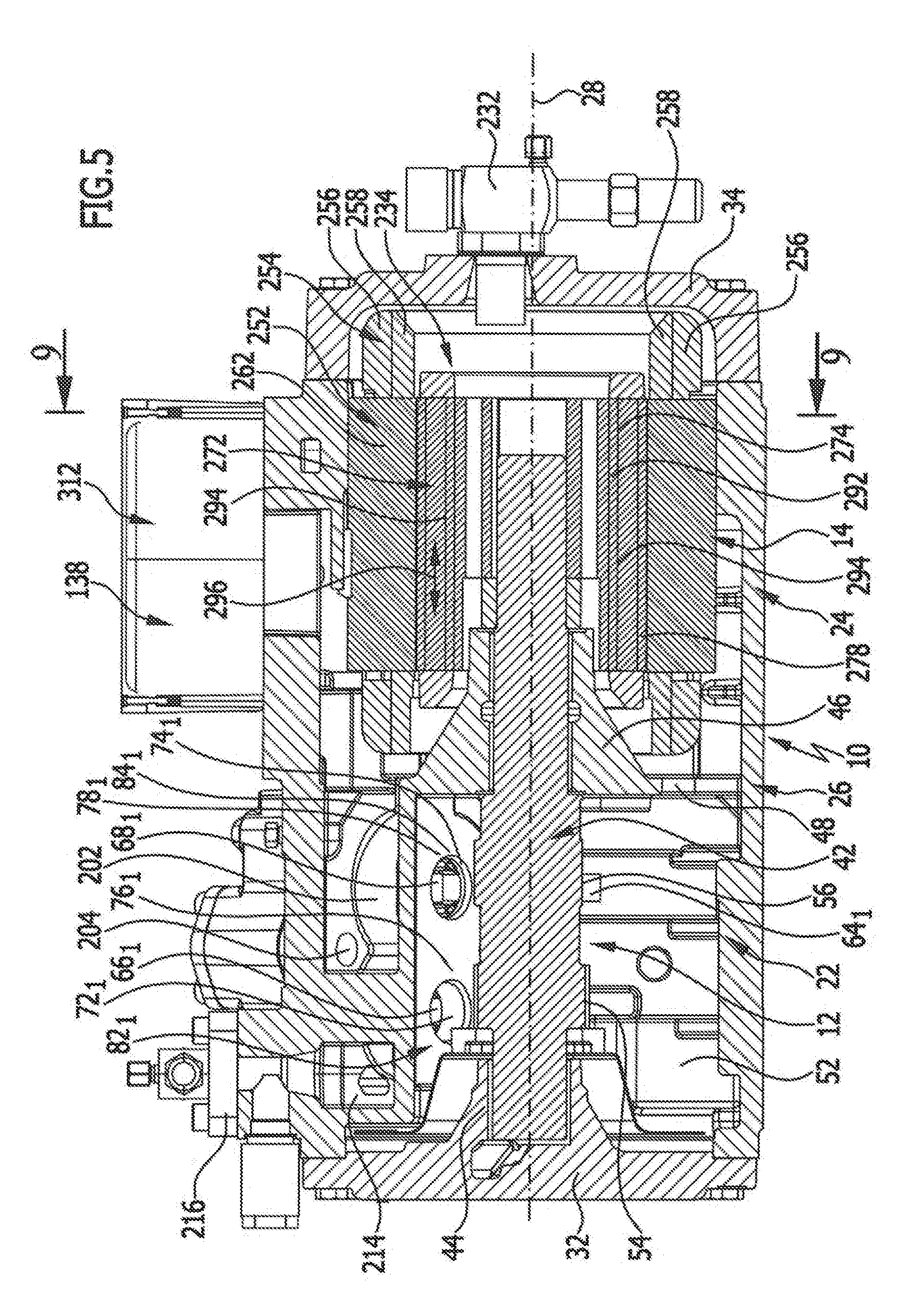
[0085] FIG. 5 shows a longitudinal section through the refrigerant compressor according to the invention;
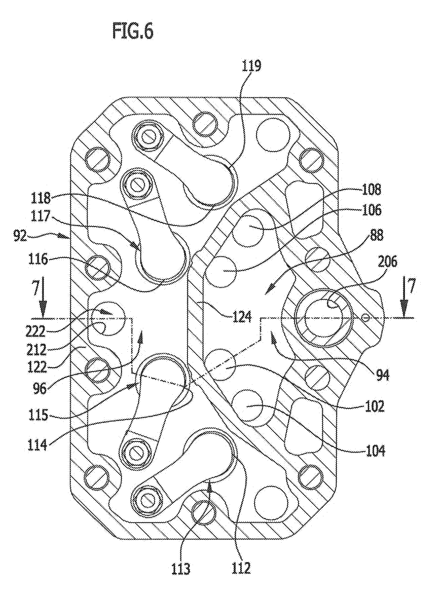
[0086] FIG. 6 shows a section along line 6-6 in FIG. 7;
[0087] FIG. 7 shows a section along line 7-7 in FIG. 6 with a closed connection channel between inlet chamber and outlet chamber;
[0088] FIG. 8 shows a section similar to FIG. 7 with open connection channel between the outlet chamber and the inlet chamber;
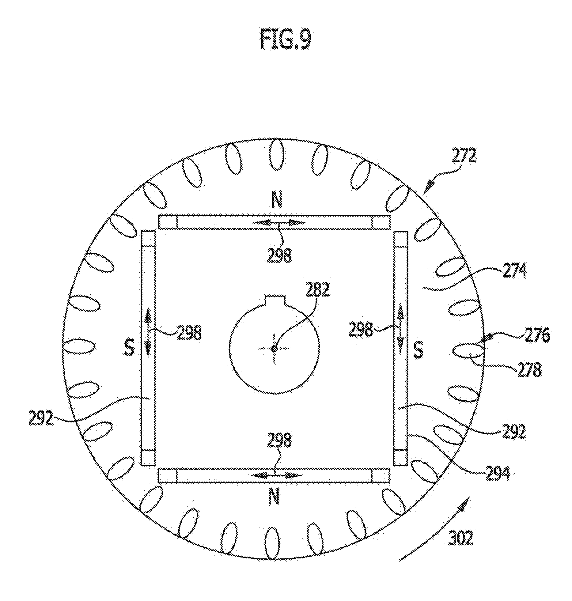
[0089] FIG. 9 shows a section along line 9-9 in FIG. 5 through a rotor of the electric motor;
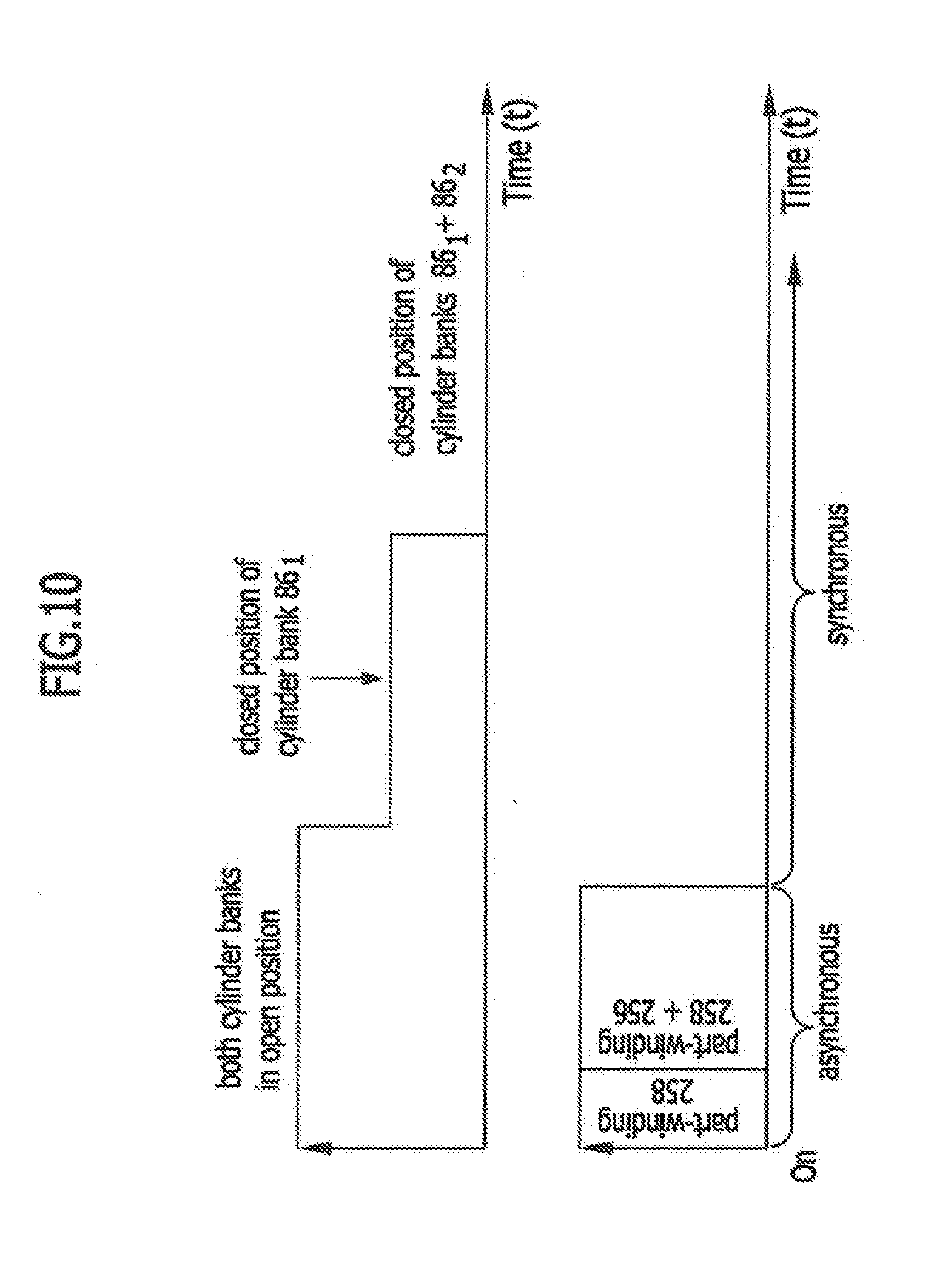
[0090] FIG. 10 shows a schematic depiction of the start-up of the electric motor; and
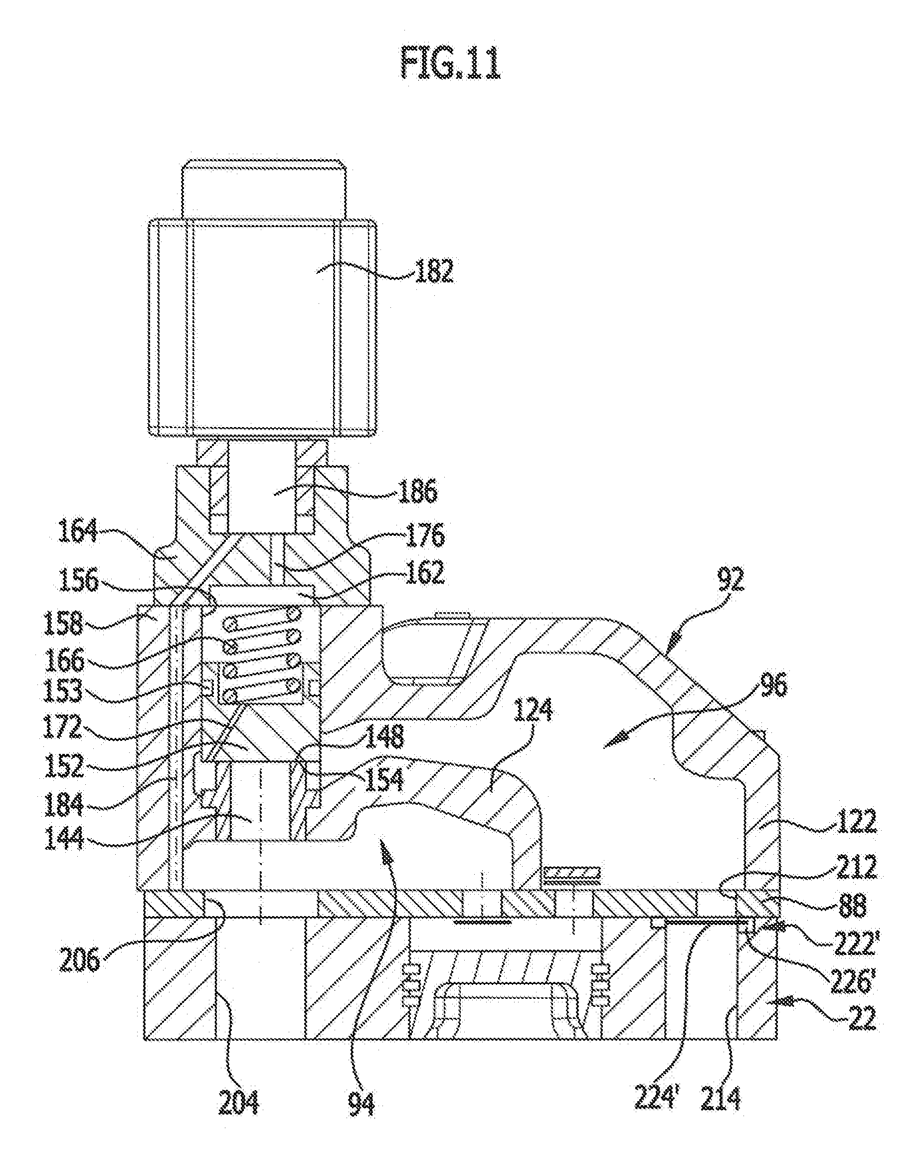
[0091] FIG. 11 shows a section similar to FIG. 7 through a second exemplary embodiment.
DETAILED DESCRIPTION OF THE INVENTION
[0092] An exemplary embodiment of a semi-hermetic refrigerant compressor according to the invention, shown in FIGS. 1 to 5, comprises an overall housing 10, in which there are arranged a reciprocating piston compressor 12 and an electric motor 14.
[0093] The overall housing 10 is formed preferably by a one-piece housing body 26, which extends in the direction parallel to a central axis 28 explained in greater detail hereinafter and is closed at the end on the side of the compressor housing portion 22 by means of a bearing cap 32 and is closed at the end in the region of the motor portion 24 by an end cap 34.
[0094] A compressor shaft denoted as a whole by 42 extends in the compressor housing portion 22 coaxially with the central axis 28 between a first shaft bearing 44 arranged on the bearing cap 32 to a second shaft bearing 46 arranged between the reciprocating piston compressor 12 and the electric motor 14, wherein the second shaft bearing 46 is held on a middle wall 48, which is molded into the housing body 26 and which delimits a drive chamber 52, which is situated between the bearing cap 32 and the middle wall 48 and through which the compressor shaft 42 extends and in which cams 54 and 56 of the compressor shaft 42 are arranged, wherein two connecting rods 62.sub.1 and 62.sub.2, or 64.sub.1 and 64.sub.2 are arranged on the cams 54 and 56 respectively, wherein the connecting rods 62.sub.1 and 62.sub.2 drive the pistons 66.sub.1 and 68.sub.1 and the connecting rods 64.sub.1 and 64.sub.2 drive the pistons 66.sub.2 and 68.sub.2.
[0095] The pistons 66 and 68 are guided in cylinder bores 72 and 74, which are formed by cylinder housings 76, 78 molded into the compressor housing portion 22, in particular molded in integrally.
[0096] Each cylinder housing 76, 78 with the cylinder bore 72, 74 and the piston 66, 68 guided therein forms a cylinder 82, 84.
[0097] The two first cylinders 82.sub.1 and 84.sub.1 molded into the compressor housing portion 22 form a first cylinder bank 86.sub.1, whereas the two cylinders 82.sub.2 and 84.sub.2 molded into the compressor housing portion 22 form a second cylinder bank 86.sub.2.
[0098] In each of the cylinder banks 86.sub.1 and 86.sub.2, the respective cylinder bores 72.sub.1, 74.sub.1 and 72.sub.2, 74.sub.2 are closed by a common valve plate 88.sub.1 and 88.sub.2, which abuts on the corresponding cylinder housings 76.sub.1 and 78.sub.1, or 76.sub.2 and 78.sub.2 in a tightly sealing manner, with a compression chamber being enclosed by each valve plate 88.sub.1 or 88.sub.2 and the respective pistons 66.sub.1 and 68.sub.1 or 66.sub.2 and 68.sub.2, and the cylinder bores 72.sub.1 and 74.sub.1 or 72.sub.2 and 74.sub.2.
[0099] The valve plates 88.sub.1 and 88.sub.2 for their part are covered in turn by a cylinder head 92.sub.1 or 92.sub.2.
[0100] As shown in FIGS. 6 to 8, an inlet chamber 94 and an outlet chamber 96 are arranged in each of the cylinder heads 92.sub.1 and 92.sub.2 and are associated with the two cylinders 82 and 84 of the corresponding cylinder bank 86.
[0101] In particular, the inlet chamber 94 is arranged above inlet openings 10.sub.2 and 10.sub.4 of the cylinder 82 and inlet openings 10.sub.6 and 10.sub.8 of the cylinder 84.
[0102] Furthermore, the outlet chamber 96 is arranged above outlet openings 112 and 114 of the cylinder 82 which are arranged in the valve plate 88, and above outlet openings 116 and 118 of the cylinder 84, the outlet openings being provided with outlet valves 113, 115, 117, 119 sitting on the valve plate 88, and the outlet chamber is arranged in particular directly adjacently to said outlet openings.
[0103] As shown in FIGS. 6 to 8, each cylinder head 92 comprises an outer body 122, which passes over the corresponding valve plate 88 and surrounds the inlet chamber 94 and the outlet chamber 96, which for their part are in turn separated from one another by a partition body 124 running within the outer body 122, wherein the partition body 124 rises starting from the respective valve plate 88 and extends in a manner spanning above the inlet chamber 94.
[0104] The outlet chamber 96 is thus arranged in the region of the valve plate 88 laterally next to the inlet chamber 94, but between the outer body 122 and the partition body 124 extends over the inlet chamber 94 at least in some regions.
[0105] In order to control the capacity of the refrigerant compressor, that is to say in order to control the compressor delivery capacity, a mechanical capacity control unit 142 actively controlled by a capacity controller 138 is associated with each cylinder head 92 and can be used to close or open a connection channel 144 between the outlet chamber 96 and the inlet chamber 94, wherein the cylinders 82, 84 associated with the cylinder head 92 compress refrigerant at full capacity when the connection channel 144 is closed (FIG. 7) and do not compress any refrigerant when the connection channel is open, since the refrigerant flows back from the outlet chamber 96 into the inlet chamber 94.
[0106] The connection channel 144 runs here through an insert part 146, which is inserted into the partition body 124 and forms a seal seat 148, which faces the outlet chamber 96 and borders a part of the outlet chamber 96 surrounding the seal seat 148 and arranged adjacently thereto.
[0107] Furthermore, the seal seat 148 faces a sealing piston 152, which for example can be placed with a metallic seal region 154 against the seal seat 148 in order to close the connection channel 144 in a tightly sealed manner and which can be raised from the seal seat 148 to such an extent that the seal region 154 is at a spacing from the seal seat 148 and therefore refrigerant can flow from the outlet chamber 96 into the inlet chamber 94.
[0108] The sealing piston 152 is preferably guided in a guide bore 156 coaxially with the insert part 146 towards the seal seat 148 and sealed by means of a piston ring 153, the guide bore being formed by a guide sleeve body 158 of the cylinder head 92 integrally formed on the outer body 122.
[0109] The sealing piston 152 itself or at least the seal region 154 is preferably made of a metal, for example a non-ferrous metal, which has a lower hardness than the metal of the seal seat 148, which for example is made of steel, in particular hardened steel.
[0110] In order to enable rapid movement of the sealing piston 152, the stroke of the sealing piston 152 between a closed position and an open position lies in particular between a quarter and half of the mean diameter of the connection channel 144.
[0111] The sealing piston 152 delimits a pressure chamber 162, which is arranged on the side of the sealing piston 152 remote from the seal region 154 and is closed on the side opposite the sealing piston 152 by a terminating body 164.
[0112] In the open position of the sealing piston, the volume of the pressure chamber 162 is in particular so small that it is less than a third, better still less than a quarter, even better still less than a fifth, advantageously less than a sixth, and even more advantageously less than an eighth of the maximum volume of the pressure chamber 162 in the closed position of the sealing piston 152.
[0113] Furthermore, a compression spring 166 is also arranged in the pressure chamber 162 and at one end is supported on the terminating body 164 and at the other end acts on the sealing piston 152 in the direction of the closed position of said piston, sitting on the seal seat 148.
[0114] Depending on the pressure application of the pressure chamber 162, the sealing piston 158 can be moved into its open position shown in FIG. 8 or into its closed position shown in FIG. 7.
[0115] To this end, the sealing piston 152 is penetrated by a throttle channel 172, which extends from the pressure chamber 162, through the sealing piston 152, to an opening which is arranged radially outside the seal region 154 on a side facing the seal seat 148, however, since the opening is arranged radially outside the seal element 154, when the sealing piston 152 is in the closed position the opening allows an entry of refrigerant that is under pressure in the outlet chamber 96 and flows around the seal seat and feeds this refrigerant in a throttled manner to the pressure chamber 162.
[0116] In addition, a relief channel 176, which can be connected by means of a solenoid valve denoted as a whole by 182 to a pressure relief channel 184 which is connected to the inlet chamber 94, leads into the pressure chamber 162, more specifically for example through the terminating body 164.
[0117] For example, the solenoid valve 182 is formed in such a way that it has a valve body 186 by means of which the connection between the pressure relief channel 184 and the relief channel 176 can be interrupted or established.
[0118] If the connection is established between the relief channel 176 and the pressure relief channel 184, the suction pressure thus prevails in the pressure chamber 162, whereas the sealing piston 152 is acted on by the pressure in the outlet chamber 96 on its side facing towards the outlet chamber 96 is therefore moved into its open position.
[0119] If, however, the connection between the pressure relief channel 184 and the relief channel 176 is interrupted by the valve body 186, the compression spring 166 presses the sealing piston 152 against the seal seat 148 and in addition high pressure flows through the throttle channel 172 into the pressure chamber 162, such that high pressure builds up in the pressure chamber 162 and presses the sealing piston 152 with the seal element 154 against the seal seat 148, additionally to the effect of the compression spring 166.
[0120] In particular, the sealing piston 152 is formed such that it extends radially beyond the seal seat 148, such that even when the sealing piston 152 is in the closed position the piston area situated radially outside the seal seat 148 and acted on by high pressure causes the sealing piston 152 to be moved against the force of the compression spring 166 into the open position, shown in FIG. 5, provided the valve body 186 of the solenoid valve 182 establishes the connection between the relief channel 176 and the pressure relief channel 184, which causes a suction pressure to be set in the pressure chamber 162.
[0121] Refrigerant under suction pressure is fed via a feed channel 202, which is molded into the compressor housing portion 22 and which leads to an inlet opening 204 leading to the valve plate 88, through which inlet opening refrigerant under suction pressure flows to a passage opening 206 in the valve plate 88 and passes therethrough into the inlet chamber 93.
[0122] In addition, as shown in FIGS. 7 and 8, the outlet chamber 96 leads to an outlet opening 212 arranged in the valve plate 88, through which outlet opening the refrigerant under pressure in the outlet chamber 96 passes into an outlet channel 214 provided in the compressor housing portion 22 and can flow to an outlet connection element 216.
[0123] In particular, the outlet opening 212 of the valve plate 88 is associated with a check valve 222, which is held on the valve plate 88, and a valve element 224 is arranged on the side of the valve plate 88 facing the outlet channel 214 and, in the case that the sealing piston 152 is in the open position and therefore in the case that the refrigerant flows from the outlet chamber 96 into the inlet chamber 94, ensures that the pressure in the outlet channel 214 does not drop, but instead is maintained by the closing check valve 222.
[0124] The check valve 222, together with a catch element 226 associated with the check valve, is preferably held on the valve plate 88 by means of a holding element 228 and provides a seal with respect to the valve plate 88.
[0125] The refrigerant compressor according to the invention is formed as a semi-hermetic compressor, such that refrigerant under suction pressure is fed by means of an inlet connection element 232 arranged on the end cap 34 to a motor compartment 234, and flows through the electric motor 14 in the direction of the middle wall 48, and passes from the motor compartment 234 into the feed channel 202, such that the electric motor 14 in the motor compartment 234 is cooled by the fed suction-side refrigerant.
[0126] The electric motor 14 in turn comprises a stator 252 which is held securely in the motor housing portion 24 and has a stator winding 254 which for example has two part-windings 256 and 258 which are used to magnetize a stator laminated core 262.
[0127] The stator 252 surrounds a rotor, denoted as a whole by 272, with a squirrel cage 276 being arranged in the rotor laminated core 274 of said rotor, as shown in FIG. 9, said squirrel cage comprising bars 278 which run parallel to a rotor axis 282 and are electrically conductively connected to one another at the ends in the peripheral direction.
[0128] Furthermore, planar permanent magnets 292 are inserted into the laminated core 274, with the flat sides 294 of said magnets extending with a longitudinal direction 296 parallel to the rotor axis 282 and with a transverse direction 298 transverse to the rotor axis 282, more specifically in such a way that the transverse directions 292 form a geometric rectangle extending around the rotor axis 282 as axis of symmetry.
[0129] The permanent magnets 292 are also formed such that, in a peripheral direction 302 about the rotor axis 282, successive permanent magnets 292 have an alternating polarity on their side facing the rotor axis 282, such that, by means of the permanent magnets 292, the rotor 272 as a whole has alternating magnetic poles in the peripheral direction.
[0130] An electric motor 14 provided with a rotor 272 of this kind operates, on account of the permanent magnets 292 provided in the rotor 272, as a synchronous motor in the normal operation, wherein on account of the permanent magnets 292 a synchronous motor of this kind has an advantageous energy efficiency and higher refrigerant delivery capacity.
[0131] The rotary field generated by the stator 252 revolves with a defined frequency on account of an energization of the stator winding 254, said frequency being caused for example in that the stator winding 254 is fed by an AC system.
[0132] In order to enable the stator 252 to be started up with a rotary field circulating at constant frequency, the rotor 272 is provided with the squirrel cage 276, which makes it possible for the electric motor 14 to start up initially as an asynchronous motor, until it has reached the rotational speed corresponding to the revolving rotary field of the stator winding, and then to operate as a synchronous motor on account of the magnetic poles caused by the permanent magnets 292.
[0133] A refrigerant compressor with an electric motor of this kind thus can be operated fed by a conventional AC system, since this motor starts up like an asynchronous motor.
[0134] It is also possible, however, to operate a refrigerant compressor of this kind with a frequency converter.
[0135] In order to facilitate the start-up of the electric motor 14 it is also possible to initially energize only one of the part-windings 256 or 258 by means of a start-up controller 310 associated with the refrigerant compressor--as shown in FIG. 10--so as to reduce the start-up current, and then to connect the other part-windings 258, 256 after a short start-up phase of the electric motor 114 as asynchronous motor.
[0136] In the event of use of the refrigerant compressor according to the invention for large pressure differences, for example as a compressor for CO.sub.2, the start-up controller 312 intervenes in the provided capacity controller 138 for the active control of the capacity control units 142 and causes at least one cylinder bank 86, preferably both cylinder banks 86.sub.1 and 86.sub.2, to be deactivated, such that in the event of deactivation of at least one cylinder bank 86 the torque required by the reciprocating piston compressor 12 is reduced, and in the event of deactivation of both cylinder banks 86.sub.1 and 86.sub.2 the torque required by the reciprocating piston compressor 12 is low, since there is no compression of refrigerant, and therefore on the one hand the start-up current of the electric motor 14 is kept low and on the other hand the electric motor then transitions very quickly from its operation as asynchronous motor into the operation as synchronous motor in which the full torque is available, such that the cylinder banks 86.sub.1 and 86.sub.2 can be activated either simultaneously or in succession (FIG. 10).
[0137] In a second exemplary embodiment, shown in FIG. 11, the parts identical to those in the first exemplary embodiment are provided with the same reference signs, and therefore reference can be made fully to the descriptions of the first exemplary embodiment.
[0138] In contrast to the first exemplary embodiment, the catch element 226' of the check valve 222' is formed in the compressor housing portion 22, for example by a recess laterally of the outlet channel 214, which recess delimits the possible path of the valve element 224' between its closed position abutting against the valve plate 88 and the maximum open position.
[0139] A catch element 226' of this kind may be provided generally in all compressor housing portions 22 of all refrigerant compressors of the same assembly, regardless of whether or not they are provided with a check valve 222', and therefore there is possible a simple retrofitting of the refrigerant compressors with a check valve 222' and in particular also with at least one mechanical capacity control unit 142 according to the invention together with a check valve 222' of this kind.
* * * * *
D00000
D00001
D00002
D00003
D00004
D00005
D00006
D00007
D00008
D00009
D00010
D00011
XML
uspto.report is an independent third-party trademark research tool that is not affiliated, endorsed, or sponsored by the United States Patent and Trademark Office (USPTO) or any other governmental organization. The information provided by uspto.report is based on publicly available data at the time of writing and is intended for informational purposes only.
While we strive to provide accurate and up-to-date information, we do not guarantee the accuracy, completeness, reliability, or suitability of the information displayed on this site. The use of this site is at your own risk. Any reliance you place on such information is therefore strictly at your own risk.
All official trademark data, including owner information, should be verified by visiting the official USPTO website at www.uspto.gov. This site is not intended to replace professional legal advice and should not be used as a substitute for consulting with a legal professional who is knowledgeable about trademark law.