Assemblies And Methods For Reducing Particulate Matter, Hydrocarbons, And Gaseous Oxides From Internal Combustion Engine Exhaust
Ghoniem; Ahmed F. ; et al.
U.S. patent application number 16/380671 was filed with the patent office on 2019-08-01 for assemblies and methods for reducing particulate matter, hydrocarbons, and gaseous oxides from internal combustion engine exhaust. The applicant listed for this patent is Tecogen, Inc.. Invention is credited to Joseph Gehret, Ahmed F. Ghoniem, Jean Roy.
| Application Number | 20190234284 16/380671 |
| Document ID | / |
| Family ID | 63104491 |
| Filed Date | 2019-08-01 |


| United States Patent Application | 20190234284 |
| Kind Code | A1 |
| Ghoniem; Ahmed F. ; et al. | August 1, 2019 |
ASSEMBLIES AND METHODS FOR REDUCING PARTICULATE MATTER, HYDROCARBONS, AND GASEOUS OXIDES FROM INTERNAL COMBUSTION ENGINE EXHAUST
Abstract
Exhaust generated from an internal combustion engine includes particulates and gas-phase volatile hydrocarbon condensables. The exhaust is cooled in an exhaust gas cooler from a first temperature to a second temperature such that a first portion of the gas-phase volatile hydrocarbon condensables in the exhaust condense to the liquid phase and a second portion of the gas-phase volatile hydrocarbon condensables in the exhaust condense on black carbon particles to form semivolatile brown carbon particulates. Some or all of the liquid-phase volatile hydrocarbon condensables and the semivolatile brown carbon particulates are trapped in a gasoline particulate filter or a catalyzed gasoline particulate filter located downstream of the exhaust gas cooler.
| Inventors: | Ghoniem; Ahmed F.; (Winchester, MA) ; Roy; Jean; (Middleton, MA) ; Gehret; Joseph; (North Reading, MA) | ||||||||||
| Applicant: |
|
||||||||||
|---|---|---|---|---|---|---|---|---|---|---|---|
| Family ID: | 63104491 | ||||||||||
| Appl. No.: | 16/380671 | ||||||||||
| Filed: | April 10, 2019 |
Related U.S. Patent Documents
| Application Number | Filing Date | Patent Number | ||
|---|---|---|---|---|
| 15892599 | Feb 9, 2018 | |||
| 16380671 | ||||
| 62457846 | Feb 11, 2017 | |||
| Current U.S. Class: | 1/1 |
| Current CPC Class: | F01N 3/32 20130101; F01N 2900/1404 20130101; F01N 2900/10 20130101; B01D 53/9454 20130101; B01D 53/96 20130101; F01N 3/0821 20130101; B01D 53/9477 20130101; B01D 2255/915 20130101; Y02T 10/12 20130101; B01D 2255/904 20130101; F01N 3/0835 20130101; F01N 9/002 20130101; B01D 53/9445 20130101; F01N 11/007 20130101; Y02A 50/20 20180101; Y02T 10/40 20130101; F01N 3/0205 20130101; F01N 3/035 20130101; F01N 3/10 20130101; F01N 13/009 20140601; F01N 9/00 20130101; F01N 13/08 20130101; F01N 2900/0418 20130101; B01D 53/9418 20130101; B01D 2255/102 20130101; B01D 53/9495 20130101; F01N 2900/08 20130101; F01N 3/021 20130101 |
| International Class: | F01N 13/00 20060101 F01N013/00; B01D 53/94 20060101 B01D053/94; F01N 3/02 20060101 F01N003/02; F01N 13/08 20060101 F01N013/08; F01N 3/10 20060101 F01N003/10; F01N 3/035 20060101 F01N003/035; F01N 9/00 20060101 F01N009/00; F01N 11/00 20060101 F01N011/00; B01D 53/96 20060101 B01D053/96; F01N 3/021 20060101 F01N003/021; F01N 3/08 20060101 F01N003/08; F01N 3/32 20060101 F01N003/32 |
Claims
1. A method of reducing emissions in exhaust generated by an engine, said exhaust comprising particulates and volatile hydrocarbon condensables, the method comprising: cooling said exhaust from a first temperature to a second temperature, said cooling causing a first portion of said volatile hydrocarbon condensables in said exhaust to condense into liquid-phase volatile hydrocarbon condensables; passing said exhaust, including said liquid-phase volatile hydrocarbon condensables and said particulates, through a gas particulate filter (GPF); and trapping, in said GPF, at least some of said liquid-phase volatile hydrocarbon condensables and at least some of said particulates.
2. The method of claim 1, wherein said first temperature is at least about 650.degree. F.
3. The method of claim 1, wherein the second temperature is about 350.degree. F. to about 450.degree. F.
4. The method of claim 1, wherein said cooling comprises: passing a first stream of said exhaust through a cooled exhaust path; passing a second stream of said exhaust through a bypass exhaust path; and combining said first and second streams of said exhaust to form a combined exhaust stream, said combined exhaust stream having said second temperature.
5. The method of claim 4, further comprising passing said first stream of said exhaust through a heat exchanger.
6. The method of claim 4, further comprising controlling a ratio of exhaust in said first stream and said second stream to adjust said second temperature.
7. The method of claim 6, further comprising adjusting an operating position of a valve to control said ratio, said valve fluidly coupled to said first stream and said second streams.
8. The method of claim 1, further comprising temporarily stopping said cooling to regenerate said GPF.
9. The method of claim 8, further comprising regenerating said GPF on a periodic basis.
10. The method of claim 8, further comprising: determining whether said engine is in an idling state or a coasting state; and regenerating said GPF only when said engine is in said idling state or said coasting state.
11. The method of claim 10, wherein said idling state and said coasting state is determined based on one of or a combination of (a) a rotational speed of said engine and (b) a fuel intake of said engine.
12. The method of claim 10, further comprising regenerating said GPF for a predetermined time period.
13. The method of claim 12, further comprising stopping said regenerating when said engine is in a drive state.
14. The method of claim 1, wherein at least some of said liquid-phase volatile hydrocarbon condensables are condensed on a first group of black carbon particles to form brown carbon particles.
15. The method of claim 14, further comprising trapping at least some of a second group of black carbon particles and at least some of said brown carbon particles in said GPF.
16. The method of claim 1, further comprising passing said cooled exhaust over one or more catalytic elements that promote chemical reactions that remove at least some carbon monoxide and at least some unburned hydrocarbons from said exhaust.
17. The method of claim 16, wherein said one or more catalytic elements are disposed in said GPF.
18. The method of claim 16, wherein said one or more catalytic elements are disposed in a second stage catalytic converter, said second stage catalytic converter disposed downstream of said GPF.
19. The method of claim 16, further comprising injecting air into said cooled exhaust before passing said exhaust through said GPF, said air increasing an oxygen content of said exhaust.
20. The method of claim 1, further comprising, prior to said cooling, passing said exhaust over one or more catalytic elements that promote chemical reactions that remove at least some NO.sub.x compounds from said exhaust.
Description
RELATED APPLICATIONS
[0001] The present application is a divisional of and claims the priority of U.S. Application Ser. No. 15/892,599, entitled "Assemblies and Methods for Reducing Particulate Matter, Hydrocarbons, and Gaseous Oxides from Internal Combustion Engine Exhaust," filed on Feb. 9, 2018, which claims priority to, and benefit of Provisional Application No. 62/457,846, filed on Feb. 11, 2017. The foregoing applications are hereby incorporated by reference.
TECHNICAL FIELD
[0002] The present application relates generally to emissions control systems for internal-combustion engines.
BACKGROUND
[0003] Vehicle emissions are highly regulated to minimize the output of environmentally-harmful exhaust emissions. The major regulated pollutants include carbon monoxide (CO), nitrogen oxide compounds (NO.sub.x), and unburned hydrocarbons (C.sub.xH.sub.y). If the vehicle exhaust is left untreated, the levels of pollutants would far exceed the emissions standards set by, for example, the U.S. Environmental Protection Agency, the states, or another country.
[0004] To meet these standards, vehicles include exhaust treatment systems that include catalytic converters, such as three-way catalytic (TWC) converters, to convert gaseous CO, NO.sub.x, and C.sub.xH.sub.y into less harmful compounds through oxidation and reduction reactions. An example of such an exhaust treatment system is illustrated in FIG. 1, which is a block diagram of an underbody of a vehicle 10. The vehicle 10 includes engine 100, first catalytic converter 110, second catalytic converter 120, and muffler 130, which are in fluid communication with one another through pipe or conduit 140. In operation, the engine 100 generates exhaust, which travels through conduit 140 to first catalytic converter 110, second catalytic converter 120, muffler 130, and then into the environment through tail pipe 150.
[0005] Recently, emissions regulators have become increasingly concerned about particulate emissions and setting limits on their levels in engine exhausts both in terms of their total mass (PM) and number (PN). These particulates are generated in internal combustion engines in three basic forms: (1) condensables (also referred to as PM2.5 when their size is less than 2.5 microns), (2) pure solids, generally referred to as "black carbon," and (3) carbon particles saturated with volatile hydrocarbon condensables, generally referred to as semivolatile particles or "brown carbon." At the high temperatures typical inside a standard exhaust treatment system (e.g., about 650.degree. F. to about 1250.degree. F.), such as that illustrated in FIG. 1, some particulates form before the exhaust gases reach the tailpipe, while some of the volatile hydrocarbon condensables remain in their gaseous phase. After exiting the tailpipe, volatile hydrocarbon condensables cool and return to the liquid phase, appearing as an aerosol. The final state of the condensables depends on the temperature, degree of dilution, other particulates in the atmosphere, etc.
[0006] Gasoline particulate filters (GPFs) and catalyzed gasoline particulate filters (cGPFs), coupled in some form to a catalytic converter, have been proposed for removing particulates from hot exhaust gases before they exit the tailpipe. However, GPFs and cGPFs cannot remove volatile hydrocarbon condensables in their gaseous form. In addition to exiting the exhaust system as a liquid (e.g., as an aerosol), gaseous volatile hydrocarbon condensables can form additional particulates downstream of the GPF/cGPF, for example in the muffler or as they exit the tail pipe.
[0007] It would be desirable to overcome one or more of the foregoing problems.
SUMMARY
[0008] Example embodiments described herein have innovative features, no single one of which is indispensable or solely responsible for their desirable attributes. The following description and drawings set forth certain illustrative implementations of the disclosure in detail, which are indicative of several exemplary ways in which the various principles of the disclosure may be carried out. The illustrative examples, however, are not exhaustive of the many possible embodiments of the disclosure. Without limiting the scope of the claims, some of the advantageous features will now be summarized. Other objects, advantages and novel features of the disclosure will be set forth in the following detailed description of the disclosure when considered in conjunction with the drawings, which are intended to illustrate, not limit, the invention.
[0009] An aspect of the invention is directed to a system for reducing emissions in exhaust generated by an engine, said exhaust comprising particulates and volatile hydrocarbon condensables, the system comprising: a heat exchanger having an inlet that receives said exhaust at a first temperature and an outlet that outputs said exhaust at a second temperature, the second temperature lower than the first temperature, wherein said heat exchanger causes at least some of said volatile hydrocarbon condensables to condense; and a gasoline particulate filter (GPF) having an inlet in fluid communication with the outlet of said heat exchanger to receive said exhaust at said second temperature, said GPF having an outlet to output said exhaust, said GPF trapping at least some liquid-phase volatile hydrocarbon condensables and at least some of said particulates, thereby reducing said emissions from said engine.
[0010] In one or more embodiments, the first temperature is at least about 650.degree. F. In one or more embodiments, the second temperature is about 350.degree. F. to about 450.degree. F. In one or more embodiments, said heat exchanger includes a valve in fluid communication with a cooled exhaust path and a bypass exhaust path, said exhaust in said cooled exhaust path being cooled by said heat exchanger, said exhaust in said bypass exhaust path bypassing said heat exchanger.
[0011] In one or more embodiments, the system further comprises a controller in electrical communication with said valve to adjust a ratio of exhaust that passes through said cooled exhaust path and said bypass exhaust path. In one or more embodiments, said controller is in electrical communication with first and second thermocouples, said first thermocouple disposed proximal to said inlet of said heat exchanger, said second thermocouple disposed in an exhaust conduit that extends from said heat exchanger to said GPF. In one or more embodiments, said controller is configured to regenerate said GPF by adjusting an operating position of said valve such that all exhaust passes through said bypass exhaust path.
[0012] In one or more embodiments, said controller is configured to regenerate said GPF on a periodic basis. In one or more embodiments, said controller is configured to regenerate said GPF only when said engine is in an idling state or a coasting state. In one or more embodiments, said controller determines whether said engine is in said idling state or said coasting state based on one of or a combination of (a) a rotational speed of said engine and (b) a fuel intake of said engine. In one or more embodiments, said controller is configured to regenerate said GPF for a predetermined time period. In one or more embodiments, said controller is configured to stop regenerating said GPF during said predetermined time period when said engine is in a drive state.
[0013] In one or more embodiments, said particulates includes black carbon particles and brown carbon particles, said brown carbon particles including said liquid-phase volatile hydrocarbon condensables. In one or more embodiments, said GPF includes a coating that traps said at least some of said liquid-phase volatile hydrocarbon condensables and said at least some of said particulates. In one or more embodiments, said GPF includes one or more catalytic elements that promote chemical reactions that remove at least some carbon monoxide and at least some unburned hydrocarbons from said exhaust.
[0014] In one or more embodiments, the system further comprises an exhaust conduit that extends from said heat exchanger to said GPF, said exhaust conduit including an air inlet to receive a stream of injected air. In one or more embodiments, the system further comprises an assembly comprising said GPF and a second stage catalytic converter. In one or more embodiments, said second stage catalytic converter includes one or more catalytic elements that promote chemical reactions that remove at least some carbon monoxide and at least some unburned hydrocarbons from said exhaust.
[0015] In one or more embodiments, the system further comprises an exhaust conduit that extends from said heat exchanger to said GPF, said exhaust conduit including an air inlet to receive a stream of injected air. In one or more embodiments, the system further comprises a first stage catalytic converter disposed between said engine and said heat exchanger, said first stage catalytic converter including one or more catalytic elements that promote chemical reactions that remove at least some NO.sub.x compounds from said exhaust.
[0016] Another aspect of the invention is directed to a method of reducing emissions in exhaust generated by an engine, said exhaust comprising particulates and volatile hydrocarbon condensables, the method comprising: cooling said exhaust from a first temperature to a second temperature, said cooling causing a first portion of said volatile hydrocarbon condensables in said exhaust to condense into liquid-phase volatile hydrocarbon condensables; passing said exhaust, including said liquid-phase volatile hydrocarbon condensables and said particulates, through a gas particulate filter (GPF); and trapping, in said GPF, at least some of said liquid-phase volatile hydrocarbon condensables and at least some of said particulates.
[0017] In one or more embodiments, said first temperature is at least about 650.degree. F. In one or more embodiments, the second temperature is about 350.degree. F. to about 450.degree. F. In one or more embodiments, said cooling comprises: passing a first stream of said exhaust through a cooled exhaust path; passing a second stream of said exhaust through a bypass exhaust path; and combining said first and second streams of said exhaust to form a combined exhaust stream, said combined exhaust stream having said second temperature. In one or more embodiments, the method further comprises passing said first stream of said exhaust through a heat exchanger. In one or more embodiments, the method further comprises controlling a ratio of exhaust in said first stream and said second stream to adjust said second temperature. In one or more embodiments, the method further comprises adjusting an operating position of a valve to control said ratio, said valve fluidly coupled to said first stream and said second streams.
[0018] In one or more embodiments, the method further comprises temporarily stopping said cooling to regenerate said GPF. In one or more embodiments, the method further comprises regenerating said GPF on a periodic basis. In one or more embodiments, the method further comprises determining whether said engine is in an idling state or a coasting state; and regenerating said GPF only when said engine is in said idling state or said coasting state. In one or more embodiments, said idling state and said coasting state is determined based on one of or a combination of (a) a rotational speed of said engine and (b) a fuel intake of said engine. In one or more embodiments, the method further comprises regenerating said GPF for a predetermined time period. In one or more embodiments, the method further comprises stopping said regenerating when said engine is in a drive state.
[0019] In one or more embodiments, at least some of said liquid-phase volatile hydrocarbon condensables are condensed on a first group of black carbon particles to form brown carbon particles. In one or more embodiments, the method further comprises trapping at least some of a second group of black carbon particles and at least some of said brown carbon particles in said GPF.
[0020] In one or more embodiments, the method further comprises passing said cooled exhaust over one or more catalytic elements that promote chemical reactions that remove at least some carbon monoxide and at least some unburned hydrocarbons from said exhaust. In one or more embodiments, said one or more catalytic elements are disposed in said GPF. In one or more embodiments, said one or more catalytic elements are disposed in a second stage catalytic converter, said second stage catalytic converter disposed downstream of said GPF. In one or more embodiments, the method further comprises injecting air into said cooled exhaust before passing said exhaust through said GPF, said air increasing an oxygen content of said exhaust. In one or more embodiments, the method further comprises, prior to said cooling, passing said exhaust over one or more catalytic elements that promote chemical reactions that remove at least some NO.sub.x compounds from said exhaust.
IN THE DRAWINGS
[0021] For a fuller understanding of the nature and advantages of the present invention, reference is made to the following detailed description of preferred embodiments and in connection with the accompanying drawings, in which:
[0022] FIG. 1 is a block diagram of an underbody of a vehicle according to the prior art;
[0023] FIG. 2 is a block diagram of an exhaust treatment system according to one or more embodiments of the invention;
[0024] FIG. 3 is a block diagram of an exhaust treatment system according to one or more embodiments of the invention;
[0025] FIG. 4 is a flow chart of a method for reducing particulate matter, hydrocarbons, nitrogen oxides, and carbon monoxide from exhausts of internal combustion engines;
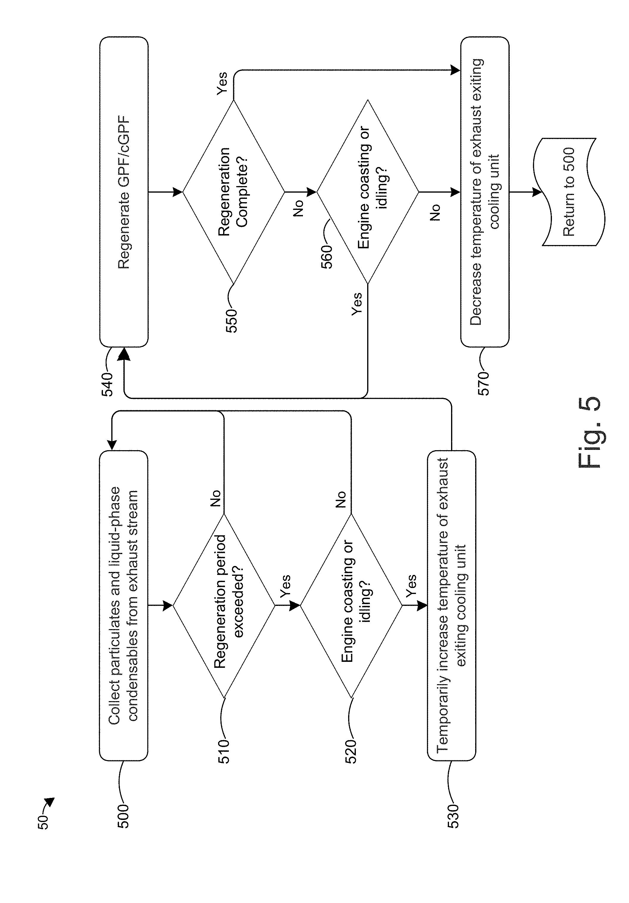
[0026] FIG. 5 is a flow chart of a method for operating and regenerating a GPF/cGPF in an exhaust treatment system;
[0027] FIG. 6 is a block diagram of an exhaust treatment system for reducing emissions of volatile hydrocarbon condensables according to one or more embodiments of the invention; and
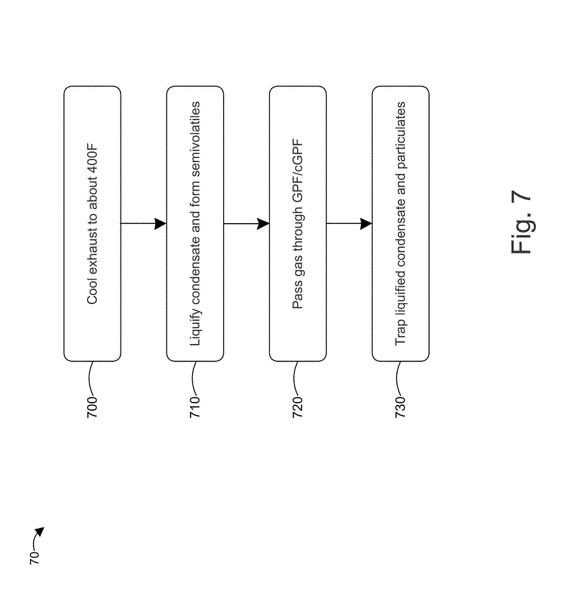
[0028] FIG. 7 is a flow chart of a method for reducing volatile hydrocarbon condensables from exhausts of internal combustion engines.
DETAILED DESCRIPTION
[0029] Aspects of the invention are directed to reducing particulate and volatile hydrocarbon emissions from the exhaust of an internal combustion engine. The exhaust gas is cooled from a first temperature to a second temperature in an exhaust gas cooler (e.g., a heat exchanger) such that a first portion of the volatile hydrocarbon condensables in the exhaust condense to the liquid phase and a second portion of the volatile hydrocarbon condensables in the exhaust condense on black carbon particles to form semivolatile brown carbon particulates. Some or all of the liquid-phase volatile hydrocarbon condensables and the semivolatile brown carbon particulates are trapped in a GPF or cGPF located downstream of the exhaust gas cooler.
[0030] FIG. 2 is a block diagram of an exhaust treatment system 20 according to one or more embodiments of the invention. The system 20 includes a first stage catalytic converter 210, an exhaust heat exchanger 220, an air pump 230, a second stage catalytic converter/cGPF 240, a muffler and tailpipe 250, and a controller 260. Exhaust from an internal combustion engine 200 enters the first stage catalytic converter 210 through a conduit, which can be connected to each cylinder of the engine 200 via a manifold. The exhaust enters the first stage catalytic converter 200 at or near the operating temperature of the engine. At steady state (i.e., after the engine has warmed up from a cold start), engine 200 generally operates in the range of about 650.degree. F. to about 1250.degree. F. As used herein, "about" means plus or minus 10% of the relevant value. Engine 200 can be a spark-ignited internal combustion engine or a diesel engine. In addition, engine 200 can be in a vehicle or it can be stationary, for example to drive a combined heat and power (CHP) system.
[0031] The engine 200 can operate with an air-fuel ratio (AFR) in the rich burn regime (i.e., less than or equal to a stoichiometric AFR). In some embodiments, the stoichiometric AFR is 14.64:1 (by mass) for gasoline. The stoichiometric AFR can vary depending on the type of fuel. For example, the stoichiometric AFR can be lower if the fuel includes ethanol. As an example, E85 fuel (85% ethanol, 15% gasoline) can have a stoichiometric AFR of about 9.8:1. When the engine 200 operates in the rich burn regime, the exhaust contains a minimal or a substantially zero oxygen content. For example, the oxygen content can be less than or equal to about 0.1% by volume, less than or equal to about 0.05% by volume, and/or less than or equal to about 0.025% by volume.
[0032] The first stage and second stage catalytic converters 210, 240 can include a catalyst comprising one or more platinum-group metals (PGMs), such as Pt, Pd, and/or Rh. In some embodiments, one or both of the first and second stage catalytic converters 210, 240 include a TWC. The first stage catalytic converter 210 promotes chemical reactions (e.g., reduction reactions) that remove at least some NO.sub.x compounds from the exhaust stream (e.g., by reducing NO.sub.x to form N.sub.2 and O.sub.2).
[0033] After passing through the first stage catalytic converter 210, the exhaust flows into the exhaust heat exchanger 220 (e.g., into an inlet of heat exchanger 220) which lowers the temperature of the exhaust from a first temperature to a second temperature, the second temperature lower than the first temperature. The first temperature can be at or near the steady-state operating temperature of the engine 200 (e.g., at least about 650.degree. F. such as about 650.degree. F. to about 1250.degree. F.). The second temperature can be about 400.degree. F., such about 350.degree. F. to about 450.degree. F., including about 375.degree. F., about 400.degree. F., about 425.degree. F., about 450.degree. F., or any value or range between any two of the foregoing values. The heat exchanger 220 includes a cooled path in which heat exchanger 220 cools the exhaust and an optional bypass path that is not cooled by the heat exchanger 220. The cooled and optional bypass paths of the heat exchanger 220 converge at the downstream end of the heat exchanger 220, where the paths mix and have a temperature T.sub.mix. The exhaust that flows through the cooled path can be cooled to a temperature of about 250.degree. F. to about 350.degree. F., including about 275.degree. F., about 300.degree. F., about 325.degree. F., or any value or range between any two of the foregoing values. The heat exchanger 220 cools the exhaust with a cooling fluid, such as radiator fluid or coolant, which is in thermal communication with the exhaust that flows through the cooled path. For example, the cooling fluid can be received from the vehicle's radiator and pass through a coil that provides a surface area for thermal communication between the cooling fluid and the exhaust flowing through the cooled path.
[0034] The temperature T.sub.mix can be adjusted by varying the flow rates (e.g., volumetric and/or mass flow rates) or the ratio of flow rates (e.g., volumetric and/or mass flow rates) of the exhaust in each path. For example, the heat exchanger 220 can include a bypass valve 270, in fluid communication (and/or fluidly coupled) with the cooled and bypass paths, that can be adjusted to vary the flow rate of the exhaust in the bypass path. When the bypass valve 270 is fully closed, all of the exhaust flows through the cooled path. When the bypass valve 270 is fully open, the exhaust flows through both the cooled and bypass paths without restriction. The bypass valve can also be partially opened or closed to limit the flow rate of exhaust through the bypass path. In an alternative embodiment, fully closing the bypass valve 270 causes all of the exhaust to flow through the cooled path, fully opening the bypass valve 270 causes all of the exhaust to flow through the bypass path, and partially opening the bypass valve 270 causes some exhaust to flow through the cooled and bypass paths, the respective amount/ratio depending on the operating position of the bypass valve 270.
[0035] In some embodiments, the heat exchanger 220 can also include a cooled path valve to open or close the cooled path. For example, during cold start the cooled path valve can be fully closed while the bypass valve 270 is fully open so the exhaust is at a maximum temperature when it passes through the second stage catalytic converter 240 to promote the chemical reactions at the second stage catalytic converter 240. Alternatively, the heat exchanger 220 can include a valve at its upstream side to direct the exhaust to either the cooled or bypass path, or to both the cooled and bypass paths. Any of the foregoing valves can be adjusted by controller 260, which receives as inputs a first temperature of the exhaust before it enters the heat exchanger 220, measured by thermocouple 225 (e.g., located proximal to the inlet of heat exchanger 220), and a second temperature of the exhaust after it exits the heat exchanger 220, measured by thermocouple 235 (e.g., located in the exhaust conduit that extends from the outlet of heat exchanger 220 to the inlet of second stage catalytic converter/cGPF 240). The controller 260 adjusts the valve(s) (e.g., valve 270) so that the second temperature is at a set point temperature of about 400.degree. F., such as about 350.degree. F. to about 450.degree. F., as discussed above.
[0036] When the exhaust gas is cooled by the heat exchanger 220 to about 400.degree. F., at least some or most of the gaseous condensables (e.g., volatile unburned hydrocarbons) undergo a phase change and condense as a liquid. Thus, the reduction in temperature of the exhaust stream causes a higher fraction of the condensables to reach their liquid phase while still contained in the exhaust gas stream. The reduction in temperature has the added benefit of forming more brown carbon when some of the gaseous condensables condense on the black carbon particles that act as nucleation sites during the phase change process.
[0037] After the exhaust gas exits the heat exchanger 220, it passes through a conduit that receives a volume of air injected by air pump 230. The injected air increases the oxygen concentration of the exhaust before it passes through the second stage catalytic converter 240. The increased oxygen concentration promotes oxidation reactions in the second stage catalytic converter that remove carbon monoxide and unburned hydrocarbons from the exhaust. The air pump 230 can inject unheated air taken from outside of the vehicle, which can have a temperature in the range of about 32.degree. F. (or lower in the winter) to about 90.degree. F. (or higher in the summer), depending on the climate in which the vehicle is located. The unheated air can cause the temperature of the exhaust to decrease. In other embodiments, the injected air is preheated in which case it has little effect on the exhaust temperature. To control for the temperature change caused by the injected air, thermocouple 235 is preferably located downstream of the injected air inlet to provide the appropriate feedback temperature to controller 260. Likewise, the injected air inlet is preferably located upstream of thermocouple 235 and downstream of heat exchanger 220. In some embodiments, the air pump 230 is also in electrical communication with the controller 260, for example to adjust the oxygen concentration based on feedback from an oxygen sensor disposed downstream of the injected air inlet.
[0038] After receiving the injected air from air pump 230, the exhaust passes into the second stage catalytic converter 240. As discussed above, the second stage catalytic converter 240 promotes chemical reactions (e.g., oxidation reactions) that remove at least some carbon monoxide and at least some unburned hydrocarbons from the exhaust stream. At the reduced temperature that the exhaust enters the second stage catalytic converter 240 (i.e., about 400.degree. F., such as about 350.degree. F. to about 450.degree. F.), the oxidation reactions occur without reforming nitrogen oxide compounds, which are controlled by emissions regulators. In some embodiment, the second stage catalytic converter 240 can also reduce the concentration of any remaining NO.sub.x in the exhaust.
[0039] The second stage catalytic converter 240 also includes a GPF. The GPF can be a separate unit (e.g., a modular portion of an assembly that includes a second stage catalytic converter) of the second stage catalytic converter 240 or it can be integrated into the second stage catalytic converter 240. In some embodiments, the second stage catalytic converter is a cGPF, which can include some or all catalytic elements that are also disposed in the second stage catalytic converter 240. For example, the cGPF can include one or more of the above-described platinum-group metals and/or it can include the catalysts that are typically included in a TWC. In some embodiments, the second stage catalytic converter 240 and/or cGPF is integrated into a single unit that also includes the muffler 250. In an alternative embodiment, a GPF is disposed between the second stage catalytic converter 240 and the injected air inlet for air pump 230.
[0040] The GPF or cGPF (in general, GPF) includes a coating 245 that traps particulate emissions, such as black and brown carbon, in the exhaust. The coating 245 can be a coating as known in the art. A three-way catalyst washcoat containing one or more PGMs and/or other metals with oxygen-storage capability may be added or included in coating 245. The coating 245 also collects the additional brown carbon and the liquid-phase condensables formed as a result of the lower exhaust temperature. Therefore, the reduction in temperature allows the GPF to trap more volatile hydrocarbon condensables, as liquid and as brown carbon, than it could when the exhaust is at a higher temperature (e.g., higher than about 400.degree. F.) where the liquid phase change does not occur. This reduction in the concentration of hydrocarbon condensables reduces the overall hydrocarbon emissions and reduces the chance of condensables forming particulates as the exhaust exits the tailpipe.
[0041] Aspects of the invention described herein can provide one or more of the following advantages:
[0042] (1) Cooling the exhaust gases in an exhaust gas cooler (e.g., heat exchanger 220) after the first stage catalytic converter (e.g., first stage catalytic converter 210) condenses a larger fraction of gaseous hydrocarbons into their liquid phase while they are still in the exhaust system (e.g., exhaust treatment system 20). These can be captured by the GPF/cGPF, making it more effective in removing a larger fraction of the condensables in liquid form and as solid particulates (e.g., brown carbon) that carry the liquefied condensables.
[0043] (2) Cooling the exhaust gases in an exhaust gas cooler (e.g., heat exchanger 220) after the first stage catalytic converter (e.g., first stage catalytic converter 210) results in the formation of particles containing large fractions of semivolatiles (e.g., brown carbon) that can be more easily captured in the GPF due to their larger size. Because a higher fraction of the particles forming after the exhaust gas cooler has larger sizes, it helps the GPF filtration system to remove more particulate mass and particulate numbers leaving the exhaust stream (e.g., exhaust treatment system 20) with a much smaller fraction of condensable hydrocarbons.
[0044] (3) Employing a catalyzed GPF (cGPF) can have the added benefit of reducing/replacing the second stage catalytic converter. Thus, the exhaust system (e.g., exhaust treatment system 20) can have approximately the same footprint and take up approximately the same amount of space as existing exhaust systems.
[0045] (4) Employing other forms of exhaust gas cooling systems (i.e., different than heat exchanger 220) that cool down the entire exhaust stream or fractions of it before treatment in the GPF/cGPF is also possible and will lead to similar benefits
[0046] (5) The systems and processes described herein can be used in internal combustion engine designs that utilize exhaust gas recirculation to reduce NO formation in the engine and/or to improve the engine efficiency.
[0047] (5) In a standard emissions system without intermediate exhaust cooling, the GPF/cGPF is regenerated by temporarily running the engine's AFR under fuel lean conditions to provide extra oxygen at the high temperatures necessary to oxidize the particulate matter caught in the filter. This may greatly increase the formation and/or reformation of nitrogen oxides, for example in the second catalytic converter. Because the above system 20 includes additional air for oxidation (i.e., air injected by air pump 230), regeneration of the GPF can be accomplished by temporarily increasing the temperature at the second stage catalytic converter 240 (e.g., by closing the cooled path valve) without changing the engine's AFR. While this may induce a slight increase in nitrogen oxides due to reformation, the overall tailpipe levels are much lower than would be produced by leaning the AFR. Nitrogen oxide reformation can be further reduced by increasing the temperature at a time when minimal fuel is consumed by the engine, such as when coasting down a hill or idling. Such regeneration can occur on a periodic basis, for example once a day, once a week, once every 1,000 miles, or other interval or periodic basis.
[0048] FIG. 3 is a block diagram of an exhaust treatment system 30 according to one or more embodiments of the invention. System 30 is the same or similar to system 20 except as described below. In place of the combined second stage catalytic converter/cGPF 240 in system 20, system 30 includes a GPF 380 disposed between the inlet for the air injected by air pump 230 and the inlet to second stage catalytic converter 340. In an alternative embodiment, the GPF 380 can be disposed between the outlet of heat exchanger 220 and the inlet for the air injected by air pump 230. The second stage catalytic converter 340 is otherwise the same or similar to second stage catalytic converter 240. For example, second stage catalytic converter 340 can include one or more platinum-group metals and/or it can include a TWC in some embodiments.
[0049] GPF 380 is the same or similar to the GPF described above with respect to second stage catalytic converter/cGPF 240. For example, GPF 380 includes a coating 345 which is the same or similar to coating 245. Thus, coating 345 can trap black carbon, brown carbon, and condensables in liquid form. It is noted that if additional GPFs are desired in system 30, the second stage catalytic converter 340 can include a second GPF or, alternatively, it can include or can be a cGPF, as described above.
[0050] In an alternative embodiment, the air pump 230 and/or the second stage catalytic converter 340 are not included in system 30. When the air pump 230 and/or second stage catalytic converter 340 are removed from system 30, the GPF 345 still functions to trap black carbon, brown carbon, and condensables in liquid form, as discussed above.
[0051] FIG. 4 is a flow chart 40 of a method for reducing particulate matter, hydrocarbons, nitrogen oxides, and carbon monoxide from exhausts of internal combustion engines. The method according to flow chart 40 can be performed on system 20 and/or 30, described above. In step 400, the exhaust is passed through a first stage catalytic converter. The first stage catalytic converter includes one or more active catalytic elements (e.g., a platinum-group metal and/or a TWC) that catalyzes a chemical reaction to reduce the concentration of nitrogen oxide compounds in the exhaust. The exhaust is generated by an internal combustion engine which can run at a stoichiometric or a rich AFR, as described above. In step 410, the exhaust is cooled to about 400.degree. F., such as about 350.degree. F. to about 450.degree. F. The exhaust can be cooled by passing some or all of it through a heat exchanger or by using another cooling unit. As discussed above, a portion of the exhaust can bypass the cooling unit and the flow rate and/or ratio of cooled and bypassed exhaust can be controlled (e.g., by valves in communication with a controller) to provide the desired temperature.
[0052] In step 420, the lower temperature causes at least a portion or most of the volatile hydrocarbon condensables to undergo a phase change into a liquid. The liquid-phase condensables can remain as liquid and/or they can condense on the black carbon particles, that act as nucleation sites during the phase change process, to form semivolatile brown carbon, as discussed above. In step 430, the oxygen concentration of the cooled exhaust is increased to at least about 0.25%, such as at least about 0.5%, at least about 0.75%, at least about 1%, or a higher concentration. The oxygen concentration can be increased by injecting air into the cooled exhaust stream. In step 440, the exhaust is passed through a GPF that includes a coating to trap the liquid-phase condensables and semivolatile particles formed in step 420 in addition to other particulates in the exhaust such as black carbon. In step 440, the exhaust is passed through a second stage catalytic converter. The second stage catalytic converter includes one or more active catalytic elements (e.g., a platinum-group metal and/or a TWC) that catalyzes chemical reactions to reduce the concentration of unburned hydrocarbons and carbon monoxide in the exhaust. The second stage catalytic converter can also reduce the concentration of nitrogen oxide compounds in some embodiments.
[0053] FIG. 5 is a flow chart 50 of a method for operating and regenerating a GPF/cGPF (in general, GPF) in an exhaust treatment system. The method according to flow chart 50 can be performed on system 20 and/or 30, described above. In step 500, the GPF collects or traps particulates, such as black and brown carbon, and liquid-phase condensables from the exhaust stream. After a first predetermined period or interval (e.g., once a day or every 100 miles), a controller in the exhaust treatment system at step 510 determines whether the regeneration period for the GPF has been exceeded. The regeneration period can be based on time (e.g., once a day, once a week, once a month, or other time period), based on mileage (e.g., every 500 miles, every 1,000 miles, or other mileage interval), based on a combination of time or mileage (e.g., once a week or once every 300 miles, whichever occurs first), or other factors. The regeneration period can occur on a periodic or a non-periodic basis. If the controller determines that the regeneration period has not been exceeded, the flow chart returns to step 500 and the GPF continues to collect particulates (e.g., black and/or brown carbon particulates) and liquid-phase condensables from the exhaust. If the controller determines that the regeneration period has been exceeded, the controller then determines at step 520 whether the engine is in an idling or coasting state (and/or that the engine is not in a drive state), for example based on the engine's rotational speed (e.g., RPMs) and/or the fuel intake of the engine. If the engine is not in an idling or coasting state (and/or if the engine is in a drive state), the flow chart 50 returns to step 500 and the GPF continues to collect particulates and liquid-phase condensables from the exhaust for a second predetermined period, or interval which can be the same or less than the first predetermined period or interval. For example, the second predetermined period can be less than an hour, such as 15 minutes, or less than 10 miles in some embodiments.
[0054] After the controller determines at step 520 that the engine is in an idling or coasting state (and/or not in a drive state), the controller at step 530 causes the temperature of the exhaust exiting the cooling unit to increase (e.g., by adjusting the bypass valve and/or cooling valve). The temperature of the exhaust exiting the cooling unit can raised to about 500.degree. F. to about 1,000.degree. F., such as about 600.degree. F., about 700.degree. F., about 800.degree. F., about 900.degree. F., or any value or range between any two of the foregoing values. In step 540, the GPF regenerates using the high temperature exhaust.
[0055] On a periodic basis or interval, the controller checks whether the regeneration is complete in step 550, which can be based on a predetermined time period. If the regeneration is complete, the flow chart 50 proceeds to step 570 where the controller causes the cooling unit to lower the temperature of the exhaust exiting the cooling unit to an operating temperature of about 400.degree. F., as discussed above. After the exhaust temperature is decreased in step 570, the flow chart 50 returns to step 500 where the GPF collects particulates and liquid-phase condensables from the exhaust. The controller also resets the first predetermined time period and the regeneration period.
[0056] If the regeneration is not complete in step 550, the flow chart proceeds to step 560 where the controller determines whether the engine continues to be in an idling or coasting state (and/or that the engine is not in a drive state). If the engine is in an idling or coasting state, the flow chart 50 returns to step 540 to continue to regenerate the GPF using the high temperature exhaust. If the engine is not in an idling or coasting state (and/or if the engine is in a drive state), the flow chart 50 proceeds to step 570 to decrease the exhaust temperature, as discussed above. After the exhaust temperature is decreased in step 570, the flow chart 50 returns to step 500 where the GPF collects particulates and liquid-phase condensables from the exhaust. The controller can reset the first predetermined period and/or the regeneration period to a secondary, lower period so that the controller attempts to complete the regeneration sooner than it normally would. Alternatively, the controller can set the first predetermined period and/or the regeneration period to zero, in which case flow chart 50 passes immediately to steps 510 and 520 in an attempt to complete the GPF regeneration process.
[0057] FIG. 6 is a block diagram of an exhaust treatment system 60 for reducing emissions of volatile hydrocarbon condensables according to one or more embodiments of the invention. Exhaust treatment system 60 includes an exhaust heat exchanger 620, a controller 660, and a GPF 680. Heat exchanger 620, controller 670, and GPF 680 can be the same as or substantially the same as heat exchanger 220, controller 260, and GPF 380, respectively. Accordingly, exhaust treatment system 60 operates in the same or substantially the same way as exhaust treatment system 30 with respect to heat exchanger 220, controller 260, and GPF 380.
[0058] In operation, exhaust from an engine passes through an exhaust conduit and into an inlet of heat exchanger 620 at a temperature at or near the operating temperature of the engine (e.g., about 650.degree. F. to about 1250.degree. F.). Upstream of the heat exchanger 620, the exhaust can optionally pass through a first stage catalytic converter, as discussed above. The controller 660 adjusts the operating position of one or more valves (e.g., bypass valve 670) in the heat exchanger 620, based on feedback from thermocouples 625, 635) to adjust the flow rate and/or ratio of exhaust that passes through a cooled path and a bypass path such that the temperature of the exhaust exiting the heat exchanger 620 is about 400.degree. F. (e.g., about 350.degree. F. to about 450.degree. F.), as discussed above. The reduction in temperature causes a portion or most of the volatile hydrocarbon condensables in the exhaust to undergo a phase change into a liquid, which are trapped or collected by GPF 680 as liquid and as brown carbon, as discussed above. GPF 680 can also collect black carbon particles in the exhaust.
[0059] In some embodiments, GPF 680 can be a cGPF as discussed above. In addition or in the alternative, a second stage catalytic converter can be disposed downstream of the GPF 680, as discussed above.
[0060] FIG. 7 is a flow chart 70 of a method for reducing volatile hydrocarbon condensables from exhausts of internal combustion engines. The method according to flow chart 40 can be performed on system 20, 30, and/or 40, described above. Steps 700, 710, and 720 can be the same as or substantially the same as steps 410, 420, and 440, respectively. It is noted that in step 720 the exhaust can pass through either a GPF or a cGPF. In step 730, the liquid-phase condensables and particulates (e.g., black carbon and/or semivolatile brown carbon particles) are trapped in the GPF/cGPF.
[0061] In the foregoing specification, the invention has been described with reference to specific embodiments. However, one of ordinary skill in the art appreciates that various modifications and changes can be made without departing from the scope of the disclosure and technology described herein. Accordingly, the specification and figures are to be regarded in an illustrative rather than a restrictive sense, and all such modifications are intended to be included within the scope of the claims and this disclosure.
* * * * *
D00000
D00001
D00002
D00003
D00004
D00005
D00006
D00007
XML
uspto.report is an independent third-party trademark research tool that is not affiliated, endorsed, or sponsored by the United States Patent and Trademark Office (USPTO) or any other governmental organization. The information provided by uspto.report is based on publicly available data at the time of writing and is intended for informational purposes only.
While we strive to provide accurate and up-to-date information, we do not guarantee the accuracy, completeness, reliability, or suitability of the information displayed on this site. The use of this site is at your own risk. Any reliance you place on such information is therefore strictly at your own risk.
All official trademark data, including owner information, should be verified by visiting the official USPTO website at www.uspto.gov. This site is not intended to replace professional legal advice and should not be used as a substitute for consulting with a legal professional who is knowledgeable about trademark law.