Tools Having A Structural Metal-matrix Composite Portion
Olsen; Garrett T. ; et al.
U.S. patent application number 16/311504 was filed with the patent office on 2019-08-01 for tools having a structural metal-matrix composite portion. This patent application is currently assigned to Halliburton Energy Services, Inc.. The applicant listed for this patent is Halliburton Energy Services, Inc.. Invention is credited to Grant O. Cook, III, Matthew Steven Farny, Garrett T. Olsen.
| Application Number | 20190234151 16/311504 |
| Document ID | / |
| Family ID | 61072843 |
| Filed Date | 2019-08-01 |


| United States Patent Application | 20190234151 |
| Kind Code | A1 |
| Olsen; Garrett T. ; et al. | August 1, 2019 |
TOOLS HAVING A STRUCTURAL METAL-MATRIX COMPOSITE PORTION
Abstract
Structural metal-matrix composites (MMC) comprising a foam matrix material infiltrated with a binder material, where the binder material binds the foam matrix material to a structural element of a tool, thereby enhancing three-dimensional reinforcement of the tool. In some instances, the structural element is a portion of a wellbore tool or a bit body, such that portions of such tools or bit bodies are composed of the structural MMC. The foam matrix material may be composed of a metallic foam, a ceramic foam, and any combination thereof.
| Inventors: | Olsen; Garrett T.; (The Woodlands, TX) ; Cook, III; Grant O.; (Spring, TX) ; Farny; Matthew Steven; (Magnolia, TX) | ||||||||||
| Applicant: |
|
||||||||||
|---|---|---|---|---|---|---|---|---|---|---|---|
| Assignee: | Halliburton Energy Services,
Inc. Houston TX |
||||||||||
| Family ID: | 61072843 | ||||||||||
| Appl. No.: | 16/311504 | ||||||||||
| Filed: | August 2, 2016 | ||||||||||
| PCT Filed: | August 2, 2016 | ||||||||||
| PCT NO: | PCT/US2016/045122 | ||||||||||
| 371 Date: | December 19, 2018 |
| Current U.S. Class: | 1/1 |
| Current CPC Class: | B22F 2998/10 20130101; E21B 10/42 20130101; B22F 2999/00 20130101; B22F 7/08 20130101; B22F 2999/00 20130101; B22F 2998/10 20130101; B22F 2999/00 20130101; E21B 10/54 20130101; B22F 2999/00 20130101; B22F 7/08 20130101; B22F 2998/10 20130101; B22F 7/08 20130101; C22C 32/00 20130101; B22F 3/11 20130101; B22F 2007/066 20130101; B22F 2007/066 20130101; C22C 2001/1057 20130101; E21B 10/46 20130101; B22F 2999/00 20130101; B22F 2007/066 20130101; C22C 1/08 20130101; C22C 2001/1073 20130101; B22F 7/08 20130101; C22C 29/00 20130101; C22C 1/08 20130101; C22C 2001/1073 20130101; B22F 2007/066 20130101; B22F 2007/066 20130101; C22C 1/08 20130101; B22F 3/1039 20130101; B22F 2999/00 20130101; B22F 3/11 20130101 |
| International Class: | E21B 10/46 20060101 E21B010/46; B22F 7/08 20060101 B22F007/08 |
Claims
1. A structural metal-matrix composite (MMC) comprising: a foam matrix material having a cellular structure, the foam matrix material selected from the group consisting of a metallic foam, a ceramic foam, and any combination thereof; a structural element of a tool; and a binder material infiltrated through the cellular structure of the foam matrix material to bind the foam matrix material and the structural element of the tool.
2. The structural MMC of claim 1, wherein the cellular structure of the foam matrix material is an open-cell foam structure or a closed-cell foam structure.
3. The structural MMC of claim 1, wherein the foam matrix material comprises the metallic foam composed of a metallic material selected from the group consisting of a metal, a metal alloy, a metal carbide, a superalloy, and any combination thereof.
4. The structural MMC of claim 1, wherein the foam matrix material comprises the ceramic foam composed of a ceramic material selected from the group consisting of an oxide ceramic, a boride ceramic, a nitride ceramic, a silicate ceramic, a carbide ceramic, diamond, and any combination thereof.
5. The structural MMC of claim 1, wherein the structural MMC further comprises reinforcement particulates.
6. The structural MMC of claim 1, wherein the binder material is at least partially selected from the group consisting of copper, nickel, manganese, zinc, and any combination thereof.
7. The structural MMC of claim 1, wherein the structural element of the tool corresponds to a portion of a wellbore tool.
8. The structural MMC of claim 1, wherein the structural element of the tool corresponds to a bit body of a drill bit.
9. A method comprising: placing a foam matrix material in a region of a mold, the foam matrix material having a cellular structure and selected from the group consisting of a metallic foam, a ceramic foam, and any combination thereof; placing a binder material in the mold; placing a structural element of a tool in the mold; heating the mold, the foam matrix material, the binder material, and the structural element of the tool to a temperature above the melting point of the binder material; infiltrating the cellular structure of the foam matrix material with the binder material; and cooling the mold, the foam matrix material, the binder material, and the structural element of the tool, wherein the infiltrated binder material binds the foam matrix material and the structural element of the tool.
10. The method of claim 9, wherein the cellular structure of the foam matrix material is an open-cell foam structure or a closed-cell foam structure.
11. The method of claim 9, wherein the structural MMC further comprises reinforcement particulates.
12. The method of claim 9, wherein the foam matrix material melts into, dissolves into, diffuses into, or reacts with the binder material during infiltration of the foam matrix material with the binder material, thereby forming a networked ductile phase.
13. The method of claim 9, wherein the foam matrix material reacts with the binder material during infiltration of the foam matrix material with the binder material, thereby forming an intermetallic phase.
14. The method of claim 9, wherein the mold corresponds to all or a portion of a wellbore tool mold.
15. The method of claim 9, wherein the mold corresponds to all or a portion of a drill bit.
16. The method of claim 9, wherein the mold corresponds to a bit body of a drill bit.
17. A drilling assembly comprising: a drill string extendable from a drilling platform and into a wellbore; a drill bit attached to an end of the drill string and including a bit body and a plurality of cutting elements coupled to an exterior portion of the bit body, the bit body composed of a structural metal-matrix composite (MMC) comprising: a foam matrix material having a cellular structure, the foam matrix material selected from the group consisting of a metallic foam, a ceramic foam, and any combination thereof; the bit body; and a binder material infiltrated through the cellular structure of the foam matrix material to bind the foam matrix material and the bit body; and a pump fluidly connected to the drill string and configured to circulate a drilling fluid to the drill bit through the wellbore.
18. The drilling assembly of claim 17, wherein the cellular structure of the foam matrix material is an open-cell foam structure or a closed-cell foam structure.
19. The drilling assembly of claim 17, wherein the foam matrix material comprises the metallic foam composed of a metallic material selected from the group consisting of a metal, a metal alloy, a metal carbide, a superalloy, and any combination thereof.
20. The drilling assembly of claim 17, wherein the foam matrix material comprises the ceramic foam composed of a ceramic material selected from the group consisting of an oxide ceramic, a boride ceramic, a nitride ceramic, a silicate ceramic, a carbide ceramic, diamond, and any combination thereof.
Description
BACKGROUND
[0001] The present disclosure relates to tools having a structural metal-matrix composite (MMC) portion and use thereof, and more specifically to tools having a structural MMC portion including a metallic and/or ceramic foam matrix material.
[0002] Traditional MMCs are composite materials having at least two constituent parts, the first being necessarily metal or metal-based and the second being the same metal in different form (e.g., a foamed metal v. an un-foamed metal), a different metal, or a non-metal material, such as an organic compound, where the first constituent forms a matrix portion of the MMC and the second constituent is dispersed or otherwise embedded into the matrix portion, such as to provide structural reinforcement and/or to bind the constituent parts together or to a structural element. Greater than two constituent parts may additionally be used to form an MMC, which may be termed hybrid composites. Such MMCs may include structural elements and be used as structural components or portions of various tools or equipment generally requiring erosion resistance, temperature resistance, and/or high impact strength. For example, MMCs may be used as part of the automotive industry (e.g., as all or portions of engines, drive shafts, disc brakes, and the like), the aviation industry (e.g., as all or portions of landing gear, and the like), the electrical industry (e.g., as all or portions of power electronic modules, power semiconductor devices, and the like), as well as other industries.
[0003] The oil and gas industry additionally employs a wide variety of wellbore tools used in downhole operations that may benefit from the erosion resistance, temperature resistance, and/or high impact strength of an MMC, such as wellbore tools for forming wellbores, wellbore tools used in completing wellbores that have been drilled, and wellbore tools used in producing hydrocarbons, such as oil and gas, from the completed wellbores. Wellbore cutting tools, in particular, are frequently used to drill oil and gas wells, geothermal wells and water wells. Wellbore cutting tools may include rotary drill bits (e.g., roller cone drill bits and fixed cutter drill bits), reamers, coring bits, under reamers, hole openers, stabilizers, and the like. For example, rotary drill bits are often formed with a bit body (sometimes referred to in the industry as a composite bit body or a matrix bit body when formed using a MMC), having cutting elements or inserts disposed at select locations about the exterior of the bit body. During drilling, these cutting elements engage and remove adjacent portions of the subterranean formation.
BRIEF DESCRIPTION OF THE DRAWINGS
[0004] The following figures are included to illustrate certain aspects of the disclosure, and should not be viewed as exclusive. The subject matter disclosed is capable of considerable modifications, alterations, combinations, and equivalents in form and function, as will occur to those skilled in the art and having the benefit of this disclosure.
[0005] FIG. 1 is a scanning electron microscope image of a closed celled metallic foam matrix material composed of nickel, prepared according to one or more examples described herein.
[0006] FIG. 2 is a cross-sectional view showing one example of a drill bit having a bit body with at least one structural MMC portion in accordance with the teachings of the present disclosure.
[0007] FIG. 3 is an isometric view of the drill bit of FIG. 1.
[0008] FIG. 4 is an end view showing one example of a mold assembly for use in forming a bit body in accordance with the teachings of the present disclosure.
[0009] FIG. 5 is a cross-sectional view showing one example of a mold assembly for use in forming a bit body in accordance with the teachings of the present disclosure.
[0010] FIG. 6 is a cross-sectional view showing one example of a drill bit in accordance with the teachings of the present disclosure.
[0011] FIG. 7 is a cross-sectional view showing one example of a drill bit in accordance with the teachings of the present disclosure.
[0012] FIG. 8 is a cross-sectional view showing one example of a drill bit in accordance with the teachings of the present disclosure.
[0013] FIG. 9 is a cross-sectional view showing one example of a matrix drill bit in accordance with the teachings of the present disclosure.
[0014] FIG. 10 is a schematic drawing showing one example of a drilling assembly suitable for use in conjunction with the drill bits of the present disclosure.
DETAILED DESCRIPTION
[0015] The present disclosure relates to tools having a structural metal-matrix composite (MMC) portion and use thereof, and more specifically to tools having a structural MMC portion including a metal-based (i.e., metallic and/or ceramic) foam matrix material, a binder material, and a structural element. These portions are distinguishable from other types of hard MMC portions that do not contain metallic and/or ceramic foam matrix material and that do not contain a structural element.
[0016] As used herein, the term "structural MMC," and grammatical variants thereof, for use in the examples of the present disclosure includes at least a metal-based (i.e., metal, ceramic, and any combination thereof) foam matrix material, a binder material, and a structural element. The term "foam matrix material," and grammatical variants thereof, as used herein refers to an inflexible material having a cellular structure of solid metal and/or ceramic capable of having a binder material and optional reinforcement (i.e., strengthening) material dispersed or otherwise embedded within the cellular structure. As used herein, the term "binder material," and grammatical variants thereof, refers to a material dispersed or otherwise embedded within a foam matrix material that is capable of binding the foam matrix material to a structural element. The binder material may, in some instances, additionally provide structural reinforcement to and/or alter the physical properties (e.g., wear resistance, friction coefficient, thermal conductivity, and the like) of the foam matrix material. The term "structural element," and grammatical variants thereof, as used herein refers to any portion of a tool providing a structural form thereto for a specific application, such as a portion of a wellbore tool (e.g., a drill bit, a leg of a drill bit, and the like). For example, the structural element may be a mandrel, a leg, a core, and insert, and/or a displacement structural element meant to supply a void space to a particular tool, and the like, without departing from the scope of the present disclosure.
[0017] The teachings of this disclosure may be applied to any tool that can be formed at least partially of structural MMC materials in accordance with the instant disclosure, including tools in any industry, such as those described above. By way of example, the teachings of the present disclosure may be illustrated with reference to wellbore tools that experience wear during contact with a wellbore or other downhole devices during downhole operations. Such wellbore tools may include tools for drilling wells, completing wells, and producing hydrocarbons from wells. Examples of such tools may include, but are not limited to, cutting tools, such as drill bits, reamers, stabilizers, and coring bits; drilling tools such as rotary steerable devices, mud motors; and other tools used downhole such as window mills, packers, tool joints, and other wear-prone tools. Even more particularly, examples of the teachings of the present disclosure may be illustrated with reference to a drill bit having a bit body with at least one portion thereof formed by a structural MMC comprising a metallic and/or ceramic foam matrix material infiltrated with a binder material, and a structural element. It is to be appreciated, nevertheless, that the examples described herein are non-limiting and the structural MMCs described herein are applicable to any tool that can be formed at least partially therefrom, without departing from the scope of the present disclosure.
[0018] Traditional composite materials may be formed by placing loose reinforcement material in particulate powder form into a mold and infiltrating the particulate powder matrix material with a reinforcement and/or binder material, followed by solidification. The structural MMCs described herein may exhibit comparatively enhanced mechanical properties, even at low volume fractions, by utilizing a metallic and/or ceramic foam matrix material (collectively simply "foam matrix material"). The foam matrix material may be composed of a metallic and/or ceramic material and may be used in lieu of traditional particulate powder matrix material. Alternatively, the foam matrix material described herein may be used in combination with an optional reinforcement material, without departing from the scope of the present disclosure (referred to herein as "optional reinforcement material"). The term "optional reinforcement material," and grammatical variants thereof, refers to herein as a material that is dispersed or otherwise embedded within the foam matrix material of the instant disclosure to provide structural reinforcement and/or alteration of physical properties to the foam matrix material, and may be in particulate (encompassing particles, fibers, and powder forms). In any examples described herein, the foam matrix material may be used in combination with optional reinforcement material(s) (e.g., optional particulate reinforcement material(s)), without departing from the scope of the present disclosure.
[0019] The foam matrix material described herein provides a structurally rigid, three-dimensional reinforcement that may behave in a similar nature to bundled fiber material. However, the foam matrix material is not designed using aspect ratios and length (as would be true for bundled fiber material), but instead based on cell type (e.g., open cell or closed cell) and cell size. The cell type and the cell size of the foam matrix material defines the type of structure it is able to provide to a structural MMC, including structural MMCs forming all or a portion of a tool, such as a wellbore tool. The rigid (inflexible), three-dimensional structure of the foam matrix materials described herein additionally physically support themselves and can be shaped as needed (and hold their shape) to provide desired capabilities for particular tools (e.g., drill bits). Indeed, the foam matrix materials described herein may be shaped (e.g., machine shaped) into various shapes to easily fit the desired shape of the structural MMC, including any all or a portion of a tool or wellbore tool it forms. Accordingly, the shape of the foam matrix material can be customized.
[0020] The structural MMCs of the present disclosure may be formed by placing a foam matrix material in a region of a mold comprising a structural element (e.g., a tool mold, such as a wellbore tool mold). The foam matrix material is then infiltrated with a binder material as a result of heating the mold. The mold is thereafter cooled, along with the foam matrix material and the binder material.
[0021] More specifically, and as discussed in greater detail below, the mold may initially have one or more displacement structural elements placed at strategic locations corresponding to the desired exterior and/or interior portions of a desired tool, for example. Thereafter, a foam matrix material is placed in the mold. The foam matrix material for use in the present disclosure is at least a metallic and/or ceramic foam matrix material and may optionally include optional reinforcement material (e.g., tungsten carbide particulates). Next, a binder material is placed in the mold, which may remain atop the foam matrix material. The mold and its contents are then heated, and when the temperature exceeds the melting point of the binder material, it infiltrates (or flows into) the foam matrix material and contacts the interior displacement structural elements. The mold and its contents (i.e., the foam matrix material, the binder material, any optional reinforcement material, and the structural element(s)) are then cooled to form the resultant structural MMC.
[0022] The foam matrix material may be placed in the mold in a pre-formed configuration (i.e., in a solid configuration, which may be preferred) or may be formed through the process of forming the structural MMC, depending on the binder material selected. The foam matrix material may be formed by introducing gas bubbles into a molten form of the material used to form the foam matrix material. The gas bubbles may be formed by injecting gas into the molten material, causing an in situ gas formation, or causing precipitation of gas previously dissolved in the molten material. Alternatively, the foam matrix material may be machined from the solid material selected to form the foam matrix material.
[0023] Advantageously, the rigid, three-dimensional structure of the foam matrix material may allow increased control over the structure and any reinforcement of the structural MMC. For example, in traditional MMCs, the use of loose matrix materials (e.g., particulates (which include powders, particles, and fibers herein)) can result in irregularities of a reinforcement structure, such as due to non-uniform physical properties, anisotrophic properties (e.g., in the case of fibers that may tend to "lie down" due to such properties), vibrational forces, gravitational forces, non-uniform infiltration, and the like. Such irregularities may cause areas of the resultant MMC to have variable properties throughout (e.g., areas of concentrated matrix material, areas of concentrated binder material, and the like). The use of the foam matrix material described herein, however, may provide a porous structure to permit flow of the binder material and any additional optional reinforcement material, thus providing better and more controlled placement therein. Additionally, where optional reinforcement material such those that are fiber-shaped are used, the fiber-shaped material may be held in place within the foam matrix material, while the pores allow the flow of any optional particulate reinforcement material and the binder material into the structure of the foam matrix material. After solidification of the structural MMC, it may be used to provide reinforcement or toughness to a portion of a tool (e.g., a bit body), depending on the composition of the foam matrix material and the remaining components of the structural MMC, such as the binder material and any optional reinforcement material.
[0024] The foam matrix material described herein comprises a metal, a ceramic, or a combination of a metal and a ceramic and has a cellular structure, as defined above. The cellular structure of the foam matrix material may be an open cell or closed cell, which may be utilized to alter the properties of the structural MMC. A "closed cell" foam matrix material, and grammatical variants thereof, refers to a foam having sealed pores (i.e., the pores are sealed from adjacent pores). Differently, an "open cell" foam matrix material, and grammatical variants thereof, refers to a foam having an interconnected network of pores (i.e., the pores are open to adjacent pores). FIG. 1 is a scanning electron microscope image of an open cell metallic foam matrix material composed of nickel, prepared according to one or more examples described herein. Closed cell configurations may allow for localized areas of toughness within the structural MMC, while open cell configurations lend to structural reinforcement that may have improved material properties, such as compression, tensile strength, and/or fracture toughness.
[0025] The size of the cell, whether open or closed, in a foam matrix material as described herein may additionally be controlled or otherwise varied to adjust the properties of a resultant structural MMC. For example, the cell size in an open celled foam matrix material may allow control over how much reinforcement is present in the structural MMC (e.g., generally the larger the openings, the less reinforcement, and vice versa). Furthermore, the foam matrix material may be customized based on the inclusion of additional optional reinforcement materials, their type, their shape, and/or their amount. In other examples, small cell size in a foam matrix material may be used to prevent or hinder optional particulate reinforcement material in certain areas, thus resulting in a binder-rich zone that may impart increased toughness and/or crack resistance to certain portions of the structural MMC. Similarly, small cell size in the foam matrix material may be used to prevent or hinder other optional reinforcement materials from entering into the foam matrix material, additionally resulting in a binder-rich zone to impart similar qualities to the structural MMC. That is, the foam matrix material may act as a filter to allow certain materials (e.g., binder materials, optional reinforcement materials, and the like, and combinations thereof) to be layered or otherwise varied relative to each other and/or to achieve specified configurations and compositions, thus imparting specific qualities to the structural MMC.
[0026] Alternatively or additionally to cell type and cell size, cell shape of the foam matrix material described herein may be used to impart certain qualities to the structural MMCs. For example, cell shape of the pores of a foam matrix material may be selected or otherwise designed to preferentially allow certain additional optional reinforcement materials having particular morphologies to pass through while precluding other morphologies. For instance, spherical or substantially spherical cell shapes may permit similarly shaped optional reinforcement materials to pass, whereas optional reinforcement materials of other shapes (e.g., irregular, plate-like, and the like) may be precluded. Use of cell shapes may thus result in certain properties, such as more dense packing or even distribution of any optional reinforcement material. Moreover, such packing or distribution of any optional reinforcement material may result in non-uniform or uniform infiltration of binder material, additionally allowing customization of the properties of the subsequent structural MMC.
[0027] The foam matrix materials described herein may be composed of any metal, ceramic, or combination thereof capable of being formed into a foam and used to form a structural MMC, as defined herein. Selection of such materials may depend on the use of the structural MMC, such as the tool or portion of the tool that it is used to form. For example, if the structural MMC forms a portion of a wellbore tool, the foam matrix material(s) should be selected for use in a downhole environment (e.g., downhole temperatures, downhole pressures, downhole friction forces, and the like).
[0028] The melting point of the foam matrix material may be selected to have a melting point greater than or less than the melting point of the binder material, without departing from the scope of the present disclosure. In any or all specific examples described herein, the composition of the foam matrix material may be selected to have a melting point greater than the melting point of the binder material(s), discussed below, selected to form the structural MMC, which may be greater than 1000.degree. C. in some instances. The term "melting point," and grammatical variants thereof, as used herein, refers to the temperature at which a solid (e.g., the foam matrix material) melts. In an example, the composition of the foam matrix material may be selected to have a melting point in the range of 1000.degree. C. to 4000.degree. C., encompassing any value and subset therebetween. For example, the composition of the foam matrix material may be selected to have a melting point of 1000.degree. C. to 1500.degree. C., or 1500.degree. C. to 2000.degree. C., or 2000.degree. C. to 2500.degree. C., or 2500.degree. C. to 3000.degree. C., or 3000.degree. C. to 3500.degree. C., or 3500.degree. C. to 4000.degree. C., or 1500.degree. C. to 3500.degree. C., or 2000.degree. C. to 3000.degree. C., encompassing any value and subset therebetween. Alternatively or additionally, the composition of the foam matrix material may be selected to have an oxidation temperature for the given atmospheric conditions that is greater than the melting point of the binder material(s).
[0029] In one or all examples, the foam matrix material described herein may have a composition that bonds with the binder material(s), so that an increased amount of thermal and mechanic stresses (or loads) can be transferred to the foam matrix material. Further, a composition that bonds with the binder material(s) may be less likely to pull out from the binder material as a crack potentially propagates in the structural MMC. That is, the binder material serves to bond the foam matrix material to one or more structural elements, and may additionally bond to the foam matrix material itself, without departing from the scope of the present disclosure.
[0030] Additionally, in one or all examples, the composition of the foam matrix material may endure temperatures and pressures experienced when forming a structurally MMC, as described in greater detail below, with little to no alloying with the binder material(s) or oxidation. However, in some instances, the atmospheric conditions may be changed (e.g., reduced oxygen content achieved via reduced pressures or gas purge) to mitigate oxidation of the foam matrix material to allow for a composition that may not be suitable for use in standard atmospheric oxygen concentrations.
[0031] In some instances, the foam matrix material is a metallic foam composed of a metal (e.g., an alkali metal, an alkaline metal, a transition metal, a post-transition metal, a lanthanide, an actinide), a metal alloy, a metal carbide, a superalloy, and the like, and any combination thereof. Specific examples of metallic foams suitable for use in conjunction as the foam matrix material described herein may include, but are not limited to, aluminum, iron, cadmium, cobalt, copper, carbon, vitreous carbon, gold, lead, molybdenum, nickel, niobium, rhenium, silicon, silver, tantalum, tin, titanium, tungsten, zinc, zirconium, copper-aluminum alloy, hafnium-carbide alloy, an iron alloy (e.g., iron-chromium alloy, iron-chromium-aluminum alloy, and the like), lanthanated molybdenum alloy, a nickel alloy (e.g., nickel-chromium-aluminum alloy, nickel-chromium alloy, nickel-iron alloy, nickel-iron-chromium alloy, nickel-manganese-gallium alloy, nickel-copper-chromium alloy, and the like), tungsten-nickel alloy, N-155 alloy, steel, stainless steel, austenitic stainless steel, ferritic steel, martensitic steel, a chromium alloy, boron carbide, silicon carbide, tantalum carbide, zinc carbide, zirconium carbide, molybdenum carbide, titanium carbide, niobium carbide, chromium carbide, vanadium carbide, iron, carbide, tungsten carbide, nickel-based superalloys, silicon nitride carbide, graphite, and the like, and any combination thereof.
[0032] Examples of suitable commercially available superalloys for use in forming the metallic foam matrix materials described herein may include, but are not limited to, INCONEL.RTM. alloys (austenitic nickel-chromium containing superalloys, available from Special Metals Corporation), WASPALOYS.RTM. (austenitic nickel-based superalloys), RENE.RTM. alloys (nickel-chrome containing alloys, available from Altemp Alloys, Inc.), HAYNES.RTM. alloys (nickel-chromium containing superalloys, available from Haynes International), INCOLOY.RTM. alloys (iron-nickel containing superalloys, available from Mega Mex), MP98T (a nickel-copper-chromium superalloy, available from SPS Technologies), TMS alloys, CMSX.RTM. alloys (nickel-based superalloys, available from C-M Group), and the like, and any combination thereof.
[0033] In some instances, the foam matrix material is a ceramic foam composed of an oxide ceramic, a boride ceramic, a nitride ceramic, a silicate ceramic, a carbide ceramic, diamond (e.g., natural diamond, synthetic diamond, and the like), and the like, and any combination thereof. Specific examples of ceramic foams suitable for use in conjunction as the foam matrix material described herein may include, but are not limited to, silicon oxide, silicon dioxide, aluminum oxide, aluminum titanate, beryllium oxide, zirconium oxide, magnesium oxide, titanium dioxide, lead zirconium titanate, titanium diboride, zirconium diboride, hafnium diboride, silicon nitride, aluminum nitride, boron nitride, titanium nitride, zirconium nitride, vanadium nitride, niobium nitride, tantalum nitride, hafnium nitride, porcelain, steatite, cordierite, mullite, and the like, and any combination thereof.
[0034] Combinations of the aforementioned metallic foams and ceramic foams may additionally be used to compose the foam matrix materials described herein, without departing from the scope of the present disclosure. Accordingly, the foam matrix materials of the present disclosure can utilize desirable benefits from one or more of the metallic and/or ceramic foams in combination.
[0035] The selection of the particular foam matrix material may depend on a number of factors, including those described above. The particular foam matrix material may be selected based on its particular eventual use in a structural MMC (including the type and use of any tool in which it is used), the selected binder material(s), any optional reinforcement material, and the like.
[0036] For example, the foam matrix material may be selected such that it will melt into, dissolve into, diffuse into, or react with the selected binder material(s) during infiltration of the foam matrix material with the binder material, as described below, thereby forming a networked ductile phase. As used herein, the term "networked ductile phase," and grammatical variants thereof, refers to a network of material that has an ability to absorb an impact or shock load with a lower propensity to fracture due to the networked material structure. Such networked ductile phase may possess pliability and/or flexibility, which may then impart toughness to the resultant structural MMC.
[0037] Alternatively, the foam matrix material may be selected such that it will react with the selected binder material(s) during infiltration of the foam matrix material with the binder material, thereby forming an intermetallic phase. As used herein, the term "intermetallic phase" refers to one or more phases comprising two elements in a covalent or ionic bond with a different crystal structure than that of the surrounding phase. Such intermetallic phase may possess high strength and/or stiffness, which may then impart strengthening, stiffening, and/or erosion resistance to the resultant structural MMC (as opposed to toughness, for example). Indeed, for example, when the structural MMC forms a portion of a wellbore tool, such as a drill bit, and is located at or near the surface of the drill bit (e.g., the bit body), stiffness of the structural MMC (e.g., by virtue of the intermetallic phase) to enhance erosion resistance of the drill bit. Stiffness may further be enhanced by including additional large particle sized optional reinforcement material within the foam matrix material.
[0038] Alternatively, the foam matrix material and binder material(s) may be selected such that they will dissolve into or react with each other during infiltration, such that after infiltration the shape of the structural MMC resembles tetrahedral molecular geometry comprising six straight edges, where the straight edges are evenly spaced and independent of one another. The tetrahedral geometry may impart high bond strength to the structural MMC. This geometry may be also be enhanced when the outer surface of the foam matrix material is designed to be thick. This geometry may provide an enhanced combination of strength and stiffness because the foam matrix material imparts strengthening (e.g., stiffness, ultimate tensile strength, and the like) in discrete, independent modules (which may or may not be themselves individual tetrahedrons) and, thus, may be less prone or not prone to crack propagation and/or crack failure. Any groupings forming the tetrahedral geometry may form the shape of the structural MMC described herein, without departing from the scope of the present disclosure.
[0039] Accordingly, the shape of the foam matrix material may be customized--the cell type, size, and shape of the foam matrix material may be customized; and/or the toughness, stiffness, or other qualities of the foam matrix material may be customized (e.g., due to the selection of certain foam matrix material types(s)). The inclusion of optional reinforcement material and its distribution within the foam matrix material, in combination with the type and reactivity of the selected binder material(s) allows further customization. Thus, the resultant structural MMC may have portions that are tough, portions that are stiff, portions that are brittle, portions that are erosion resistant, and the like by strategically forming the structural MMC. Moreover, such customization allows prudent use of certain components or compositional elements that may be expensive or in short supply, as these components and others can be selectively included in the structural MMC.
[0040] In any or all examples, the selected foam matrix material may itself be further treated to alter the material properties of the selected foam material. For example, the selected foam material may be a metallic foam composed of a metal alloy, and the metal alloy may be itself heat treated such that increased strength or stiffness is imparted prior to forming it into the foam matrix material. Alternatively or in addition to, the material properties of the foam material selected for forming the foam matrix material can be altered during the infiltration process (e.g., to impart increased strength or stiffness). That is, the selected foam material may be a metal alloy that is selected (or formulated) such that the infiltration process alone during forming the structural MMC imparts the requisite heat input to alter the properties of the metal alloy, and thus the structural MMC, such as by causing precipitation hardening throughout the foam material forming the foam matrix material. Accordingly, no additional manufacturing steps would be needed in addition to the manufacture of the structural MMC alone to alter the properties of the foam matrix material. Alternatively, the selected foam material forming the foam matrix material may be a ceramic material that can be pretreated to improve fracture resistance or bonding with the selected binder material(s).
[0041] In any or all examples of the structural MMCs described herein, an optional reinforcement material may be used in combination with the ceramic and/or metallic foam matrix materials and/or the binder material to further customize the structural MMC (e.g., to provide additional reinforcement). Such optional reinforcement materials may include, but are not limited to, reinforcing particulates, encompassing powders, particles, and fibers, and the like, and any combination thereof. These optional reinforcement materials may be dispersed or embedded in the foam matrix material prior to the step of infiltration with the binder material(s) or may be directly included in the binder material(s) and placed into the foam matrix material during the infiltration process (e.g., with the binder material(s)), without departing from the scope of the present disclosure.
[0042] As used herein, the "reinforcing particulates" have a shape such that they are substantially spherical, polygonal, or fibrous in shape. As used herein, the term "substantially spherical," and grammatical variants thereof, refers to a material that has a morphology that includes spherical geometry and elliptic geometry, including oblong spheres, ovoids, ellipsoids, capsules, and the like, and hybrids thereof. The term "polygonal," and grammatical variants thereof, as used herein, refers to shapes having at least two straight sides and angles. Examples of polygonal shapes may include, but are not limited to, a cube, cone, pyramid, cylinder, rectangular prism, cuboid, triangular prism, icosahedron, dodecahedron, octahedron, pentagonal prism, hexagonal prism, hexagonal pyramid, and the like, and hybrids thereof. As used herein, the term "fibrous," and grammatical variants thereof, refers to fiber-shaped substances having aspect ratios of greater than 2, or in the range of 2 to 500, encompassing any value and subset therebetween. For example, the fibrous reinforcing particles may have an aspect ratio of 2 to 50, or 50 to 100, or 100 to 200, or 200 to 300, or 300 to 400, or 400 to 500, or 50 to 450, or 100 to 400, or 150 to 350, or 200 to 300, encompassing any value and subset therebetween. Accordingly, "fibrous" shapes encompass fibers, rods, wires, dog bones, whiskers, ribbons, discs, wafers, flakes, rings, and the like, and hybrids thereof. As used herein, the term "dog bone" refers to an elongated structure like a fiber, whisker, or rod where the cross-sectional area at or near the ends of the structure are greater than a cross-sectional area therebetween. As used herein, the "aspect ratio" refers to the ratio of the longest dimension to the thickness.
[0043] A collection of fiber-shaped reinforcing particulates may be arranged to form a 2-dimensional or 3-dimensional structure (e.g., an oriented wool, a disoriented wool, or a mesh). As used herein, the term "oriented wool" refers to an entangled mass of fibers where at least 90% of the fibers are oriented within 25.degree. of each other (e.g., steel wool), which may be a result of the manufacturing process, entanglement method, or an orienting process (e.g., stretching a disoriented wool). As used herein, the term "disoriented wool" is an entangled mass of continuous fibers that are less oriented than an oriented wool. As used herein, the term "wool" encompasses both oriented wools and disoriented wools.
[0044] The size of the reinforcing particulates may be such that they have a unit mesh particle size in the range of 0.05 micrometer (.mu.m) to 2000 .mu.m, encompassing any value and subset therebetween. Accordingly, the term "reinforcing particulates" encompasses powder forms. For example, the size of the reinforcing particulates may have a unit mesh size of 0.05 .mu.m to 5 .mu.m, or 5 .mu.m to 400 .mu.m, or 400 .mu.m to 8000 .mu.m, or 800 .mu.m to 1200 .mu.m, or 1200 .mu.m to 1600 .mu.m, or 1600 .mu.m to 2000 .mu.m, or 400 .mu.m to 1600 .mu.m, or 800 .mu.m to 1200 .mu.m, encompassing any value and subset therebetween. As used herein, the term "unit mesh particle size" or simply "unit mesh size" refers to a size of an object (e.g., a particulate) that is able to pass through a square area having each side thereof equal to the specified numerical value provided herein. One skilled in the art would recognize that the length of the any fiber-shaped reinforcing particulate will depend on their unit mesh size diameter.
[0045] The optional reinforcing particulates may be composed of any material described above with reference to the metallic foam and/or ceramic foams for use in forming the foam matrix materials described herein and below with reference to the binder materials. The optional reinforcement particulates may additionally be composed of sand, glass materials, polymer materials (e.g., polystyrene, polyethylene, etc.), nut shell pieces, wood, cements (e.g., Portland cements), fly ash, carbon black powder, silica, alumina, alumino-silicates, fumed carbon, carbon black, graphite, mica, titanium dioxide, barite, meta-silicate, calcium silicate, calcium carbonate, dolomite, nepheline syenite, feldspar, pumice, volcanic material, kaolin, talc, zirconia, boron, shale, clay, sandstone, mineral carbonates, mineral oxide, iron oxide, formation minerals, any of the aforementioned mixed with a resin to form cured resinous particulates, and any combination thereof.
[0046] Additionally, the optional reinforcing particulates may be selected to have one, more than one, or all of the various characteristics discussed above with reference to the foam matrix material (e.g., a melting point above the melting point of the binder material; an oxidation temperature for the given atmospheric conditions that is greater than the melting point of the binder material(s); a material that melts into, dissolves into, diffuses into, or reacts with the binder material during infiltration; and the like; and any combination thereof).
[0047] Binder material compositions may be any material suitable for use in forming a structural MMC in accordance with the present disclosure, and may be the same material in different form (i.e., a non-foam) or a different material selected for forming the foam matrix material, provided that it is able to at least bond the foam matrix material and the structural element. As an example, the binder material may be nickel and the foam matrix material may also be nickel. Accordingly, the materials available for forming the binder material and the foam matrix material may be identical, without departing from the scope of the present disclosure. In some, but not all examples of the instant disclosure, the composition of the foam matrix materials may be chosen to have a melting point equal to or greater than the melting point of the binder material for a particular structural MMC.
[0048] Examples of suitable binder materials for use in the present disclosure may include, but are not limited to, copper, nickel, cobalt, iron, aluminum, molybdenum, chromium, manganese, tin, zinc, lead, silicon, tungsten, boron, phosphorous, gold, silver, palladium, indium, any mixture thereof, any alloy thereof, and any combination thereof. Additional specific examples of binder materials may include, but are not limited to, copper-phosphorus, copper-phosphorous-silver, copper-manganese-phosphorous, copper-nickel, copper-manganese-nickel, copper-manganese-zinc, copper-manganese-nickel-zinc, copper-nickel-indium, copper-tin-manganese-nickel, copper-tin-manganese-nickel-iron, gold-nickel, gold-palladium-nickel, gold-copper-nickel, silver-copper-zinc-nickel, silver-manganese, silver-copper-zinc-cadmium, silver-copper-tin, cobalt-silicon-chromium-nickel-tungsten, cobalt-silicon-chromium-nickel-tungsten-boron, manganese-nickel-cobalt-boron, nickel-silicon-chromium, nickel-chromium-silicon-manganese, nickel-chromium-silicon, nickel-silicon-boron, nickel-silicon-chromium-boron-iron, nickel-phosphorus, nickel-manganese, copper-aluminum, copper-aluminum-nickel, copper-aluminum-nickel-iron, copper-aluminum-nickel-zinc-tin-iron, and the like, and any combination thereof. Examples of commercially available binder materials may include, but are not limited to, VIRGIN.TM. Binder material 453D (copper-manganese-nickel-zinc, available from Belmont Metals, Inc.); copper-tin-manganese-nickel and copper-tin-manganese-nickel-iron grades 516, 519, 523, 512, 518, and 520 available from ATI Firth Sterling; and any combination thereof. Binder materials comprising copper, nickel, manganese, zinc, and any combination thereof, alone or with other materials may be preferred.
[0049] By way of non-limiting example, FIGS. 2-9 provide examples of implementing the structural MMCs comprising a metallic and/or ceramic foam matrix material infiltrated with a binder material(s), and including a structural element, described herein in drill bits. One skilled in the art will recognize how to adapt these teachings to other tools or wellbore tools, including, but not limited to, all those mentioned herein, or portions thereof.
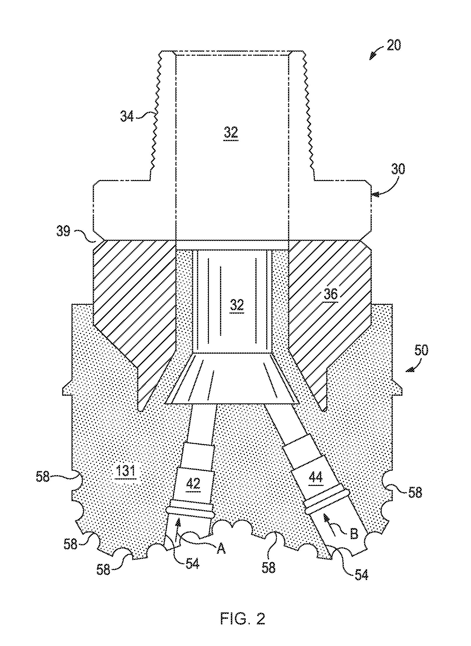
[0050] FIG. 2 is a cross-sectional view showing one example of a drill bit 20 formed with a bit body 50 that has a structural MMC portion 131 comprising a foam matrix material, a binder material infiltrated through the foam matrix material, and one or more structural elements. As used herein, the term "drill bit" encompasses rotary drag bits, drag bits, fixed cutter drill bits, and any other drill bits having a bit body capable of incorporating the teachings of the present disclosure (i.e., capable of incorporating a structural MMC).
[0051] As shown in FIG. 2, the drill bit 20 may include a structural element metal shank 30 with a structural element metal blank 36 securely attached thereto (e.g., at weld location 39). The metal blank 36 may extend into the bit body 50. The metal shank 30 may have a threaded connection 34 distal to the metal blank 36. The metal shank 30 and metal blank 36 are generally cylindrical structural elements that at least partially define corresponding fluid cavities 32 that fluidly communicate with each other. The fluid cavity 32 of the metal blank 36 may further extend into the bit body 50. At least one structural element flow passageway (shown as two flow passageways 42 and 44) may extend from the fluid cavity 32 to the exterior portions of the bit body 50. Structural element nozzle openings 54 may be defined at the ends of the flow passageways 42 and 44 at the exterior portions of the bit body 50.
[0052] A plurality of indentations or pockets 58 may be formed at the exterior portions of the bit body 50 and may be shaped to receive corresponding cutting elements (shown in FIG. 3).
[0053] Regarding crack propagation in a bit body 50, in some instances, cracks may originate at or near the nozzle openings 54 and propagate up flow passageways 42 and 44 in the direction of arrows A and B, respectively. As described further herein, the stress (or load) of the fracture may transfer to the structural MMC, and more particularly to the foam matrix material described herein, and mitigate crack propagation. Therefore, strengthening of the foam matrix material that is at a location non-parallel to the crack propagation direction provide some degree of load transfer and mitigation of crack propagation, which may be achieved using the foam shape and size; cell type, size, and shape; foam material selection; and the like, as described above. In some instances, the foam matrix material (or a portion thereof) is strengthened at a location substantially perpendicular (e.g., within 25.degree. of perpendicular) to the crack propagation direction to maximize stress transfer and minimize crack propagation.
[0054] FIG. 3 is an isometric view showing one example of a drill bit 20 that may be formed with the bit body 50 formed by a structural MMC comprising a foam matrix material, a binder material infiltrated through the foam matrix material, and a plurality of structural elements in accordance with the teachings of the present disclosure. As illustrated, the drill bit 20 includes the metal blank 36 and the metal shank 30, as generally described above with reference to. FIG. 2. The bit body 50 includes a plurality of cutter blades 52 formed on the exterior of the bit body 50. Cutter blades 52 may be spaced from each other on the exterior of the structural MMC bit body 50 to form fluid flow paths or junk slots 62 therebetween.
[0055] As illustrated, the plurality of pockets 58 may be formed in the cutter blades 52 at selected locations to receive corresponding cutting elements 60 (also known as cutting inserts), securely mounted (e.g., via brazing) in positions oriented to engage and remove adjacent portions of a subterranean formation during drilling operations. More particularly, the cutting elements 60 may scrape and gouge formation materials from the bottom and sides of a wellbore during rotation of the drill bit 20 by an attached drill string (not shown). For some applications, various types of polycrystalline diamond compact (PDC) cutters may be used as cutting elements 60. A drill bit having such PDC cutters may sometimes be referred to as a "PDC bit".
[0056] A nozzle 56 may be disposed in each nozzle opening 54. For example, nozzles 56 may be described or otherwise characterized as "interchangeable" nozzles.
[0057] Regarding crack propagation in a bit body 50, in some instances, cracks may develop in the blades 52 from any direction due to impact and torque experienced during drilling. Because the cracks may originate from all directions, the foam matrix material of the structural MMC may be uniformly strengthened using one or more methods described above, including the inclusion of additional reinforcing particulates, to reinforce the blades 52.
[0058] A wide variety of molds may be used to form a structural MMC bit body and associated drill bit in accordance with the teachings of the present disclosure.
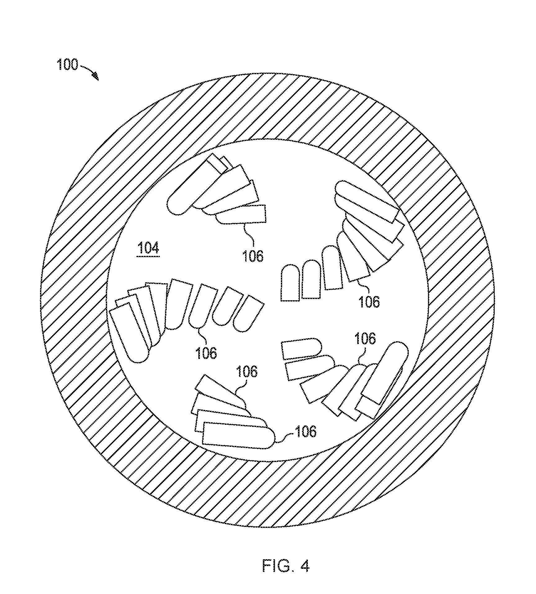
[0059] FIG. 4 is an end view showing one example of a mold assembly 100 for use in forming a bit body incorporating teachings of the present disclosure. A plurality of structural element mold inserts 106 may be placed within a cavity 104 defined by or otherwise provided within the mold assembly 100. The mold inserts 106 may be used to form the respective pockets in blades of the bit body. The location of mold inserts 106 in cavity 104 corresponds with desired locations for installing the cutting elements in the associated blades. Mold inserts 106 may be formed from various types of material such as, but not limited to, consolidated sand and graphite, or any material described herein with reference to the foam matrix material, the binder material, and the optional reinforcement material.
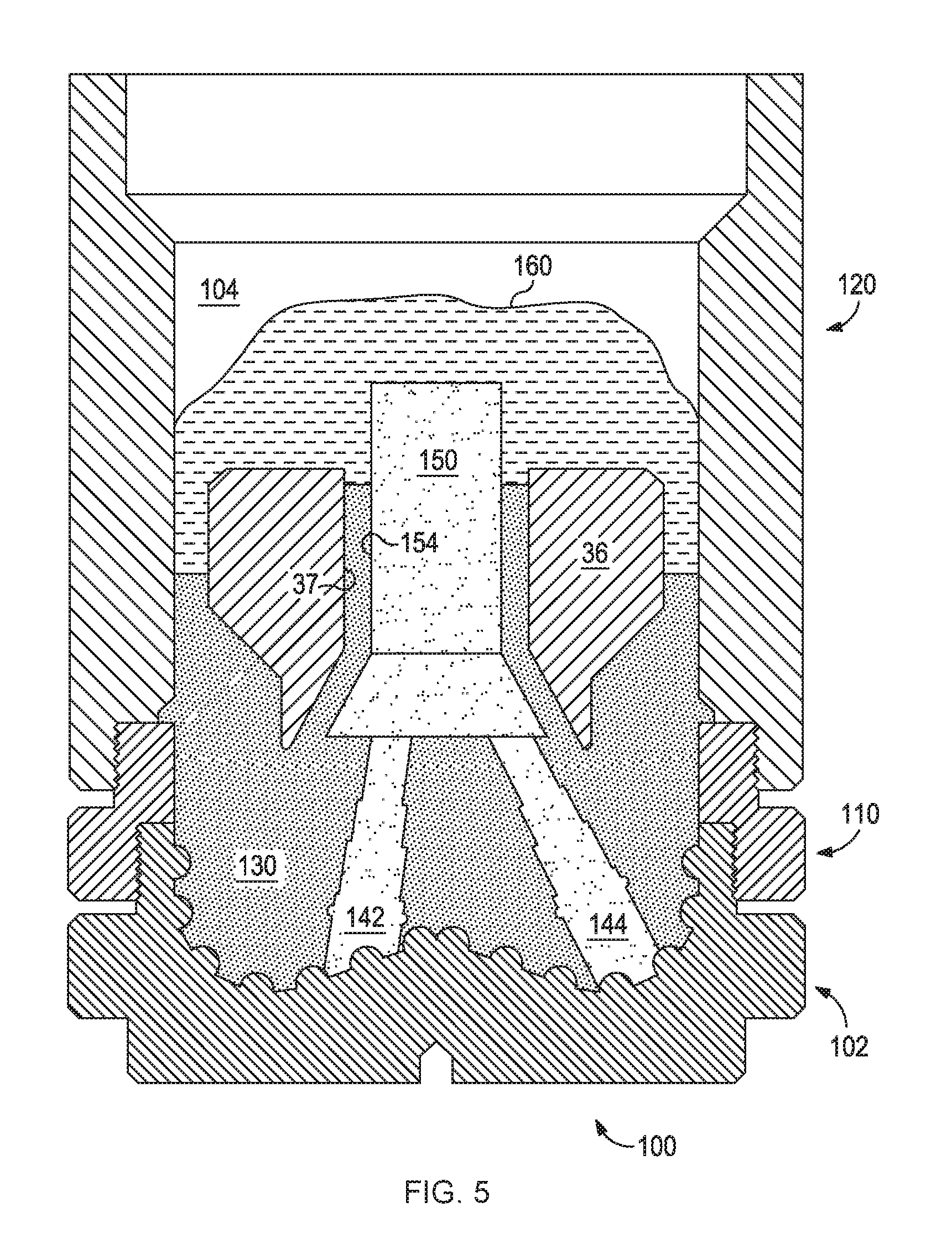
[0060] FIG. 5 is a cross-sectional view of the mold assembly 100 of FIG. 4 that may be used in forming a bit body incorporating teachings of the present disclosure. The mold assembly 100 may include several components such as mold 102, a gauge ring or connector ring 110, and a funnel 120. Mold 102, gauge ring 110, and funnel 120 may be formed from any material described herein with reference to the foam matrix material, the binder material, such as from graphite. Various techniques may be used to manufacture the mold assembly 100 including, but not limited to, machining a graphite blank to produce the mold assembly 100 with the associated cavity 104 having a negative profile or a reverse profile of desired exterior features for a resulting bit body. For example, the cavity 104 may have a negative profile that corresponds with the exterior profile or configuration of the blades 52 and the junk slots 62 formed therebetween, as shown in FIGS. 2-3.
[0061] Various types of temporary structural element displacement materials may be installed within cavity 104, depending upon the desired configuration of a resulting drill bit. Additional structural element mold inserts (not expressly shown) may be formed from various materials (e.g., consolidated sand and/or graphite) may be disposed within cavity 104. Such mold inserts may have configurations corresponding to the desired exterior features of the drill bit (e.g., junk slots).
[0062] Displacement materials (e.g., consolidated sand) may be installed within the mold assembly 100 at desired locations to form the desired exterior features of the drill bit (e.g., the fluid cavity and the flow passageways). Such structural element displacement materials may have various configurations. For example, the orientation and configuration of the consolidated sand legs 142 and 144 may be selected to correspond with desired locations and configurations of associated flow passageways and their respective nozzle openings. The consolidated sand legs 142 and 144 may be coupled to threaded receptacles (not expressly shown) for forming the threads of the nozzle openings that couple the respective nozzles thereto.
[0063] Other structural elements, such as a relatively large, generally cylindrically-shaped consolidated sand core 150 may be placed on the legs 142 and 144. Core 150 and legs 142 and 144 may be sometimes described as having the shape of a "crow's foot." Core 150 may also be referred to as a "stalk." The number of legs 142 and 144 extending from core 150 will depend upon the desired number of flow passageways and corresponding nozzle openings in a resulting bit body. The legs 142 and 144 and the core 150 may also be formed from graphite or other suitable materials, including any of those described herein with reference to the foam matrix material(s), the binder material(s), and the optional reinforcement material(s).
[0064] After desired displacement materials, including for example core 150 and legs 142 and 144, have been installed within the mold assembly 100, the foam matrix material 130 may then be placed within or otherwise introduced into the mold assembly 100. In an example, the foam matrix material described herein may be placed in a desired area or portion of the mold assembly 100 and optional reinforcement material (e.g., particulate powder of tungsten carbide) added around the placed foam matrix material. Alternatively, the foam matrix material may have optional reinforcement material(s) (e.g., particulate powder of tungsten carbide) mixed therein. In another example, the foam matrix material described herein may be formed into a specific shape for use in forming the solidified or hardened structural MMC, and if present, optional reinforcement material (e.g., particulate powder of tungsten carbide) may be dispersed or otherwise embedded therein. For example, the foam matrix material as a whole may be spiral-shaped, a mesh, or an oriented wool and placed around the legs 142 and 144, which, with reference to FIG. 2, may be oriented to mitigate crack propagation up flow passageways 42 and 44 in the direction of arrows A and B, respectively. In another example, the foam matrix material may be formed to have cell sizes allowing sufficient interstitial spacing for optional reinforcement material particles to flow therethrough. In some instances, the foam matrix material may be fabricated with such small cell sizes that they do not allow optional reinforcement material particles to migrate into the voids defined by the pores in the foam matrix material.
[0065] Vibration may be used to increase the packing efficiency of the foam matrix material 130 (e.g., to pack optional reinforcement material(s) or the binder material within the structure of a foam matrix material). In an example, after the foam matrix material 130 has been added to the mold assembly 100, the structural element metal blank 36 may then be placed within the mold assembly 100. In one or all examples, the foam matrix material 130 may be designed to have inserts for placing the metal blank 36. The metal blank 36 preferably includes inside diameter 37, which is larger than the outside diameter 154 of sand core 150. Additional foam matrix material 130 may be added to a desired level within the cavity 104, which may be designed to a specific shape for inclusion therein.
[0066] As illustrated, binder material 160 may be placed on top of the foam matrix material 130, metal blank 36, and core 150. Alternatively, the binder material 160 may be included with at least a portion of the foam matrix material 130. The binder material 160 may be covered with a flux layer (not expressly shown). Alternatively, a binder material 160 bowl (not expressly shown) disposed at the top of the funnel 120 may be used to contain the binder material 160, which, during infiltration, will then flow down into the foam matrix material 130, which may or may not include optional reinforcement material. In alternative examples, the binder material 160 includes optional reinforcement material (e.g., particulate powder tungsten carbide), regardless of whether the foam matrix material 130 includes such optional materials, without departing from the scope of the present disclosure.
[0067] A cover or lid (not expressly shown) may be placed over the mold assembly 100. The mold assembly 100 and materials disposed therein may then be preheated and then placed in a furnace, or directly placed in a furnace. When the furnace temperature reaches or optionally exceeds the melting point of the binder material 160, the binder material 160 may liquefy and infiltrate the foam matrix material 130, binding the foam matrix material 130 to the various structural elements.
[0068] After a predetermined amount of time allotted for the liquefied binder material 160 to infiltrate the foam matrix material 130, the mold assembly 100 may then be removed from the furnace and cooled at a controlled rate. Once cooled, the mold assembly 100 may be broken away to expose the bit body having a structural MMC comprising a foam matrix material, a binder material, various structural elements, and any optional reinforcement material. Subsequent processing and machining, according to well-known techniques, may be used to, produce a drill bit having the desired bit body, if necessary.
[0069] The structural MMC portion may be homogeneous throughout or heterogeneous throughout the bit body as illustrated in FIGS. 2-3.
[0070] In an example, the structural MMC portion may be localized within a portion of the bit body with the remaining portion being formed by a hard composite that is not a structural MMC. In some instances, localization may provide mitigation for crack initiation and propagation while minimizing the additional cost that may be associated with some structural MMC materials and/or processing. Further, the inclusion of the foam matrix material in the bit body may, in some instances, reduce erosion properties of the bit body because of the lower concentration of reinforcing particles. Therefore, in some instances, localization of the foam matrix material to only a portion of the bit body may mitigate any reduction in erosion properties thereat.
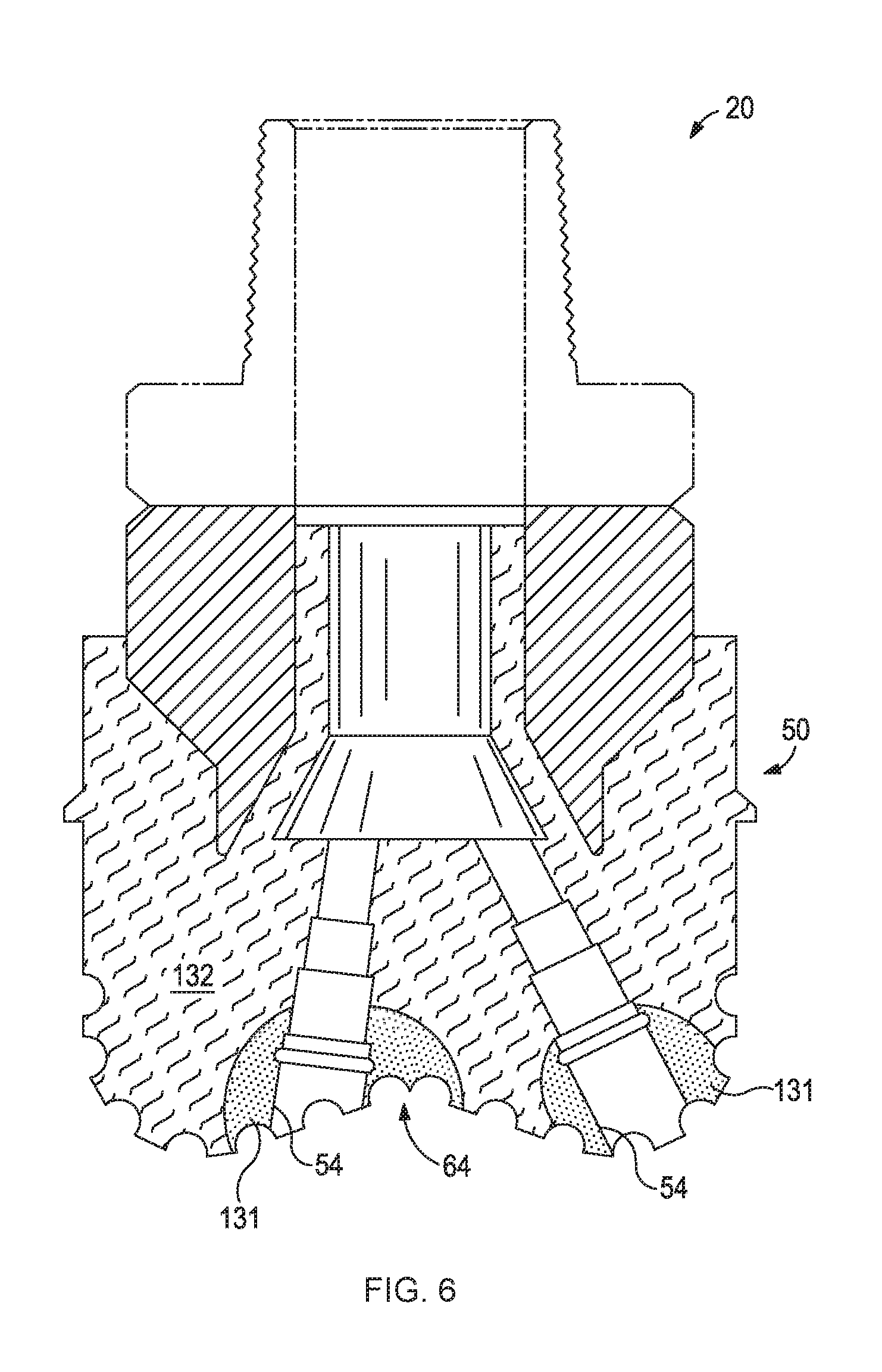
[0071] For example, FIG. 6 is a cross-sectional view showing one example of a drill bit 20 formed with a bit body 50 having a hard composite portion 132 that is not a structural MMC in combination with one or more structural MMC portions 131 (two shown) in accordance with the teachings of the present disclosure. The structural MMC portions 131 are shown to be located proximal to the nozzle openings 54 and an apex 64, two structural element areas of bit bodies that typically have an increased propensity for cracking. As used herein, the term "apex," and grammatical variants thereof, refers to the central portion of the exterior surface of the bit body that engages the formation during drilling. Typically, the apex of a drill bit is located at or proximal to where the blades 52 (FIG. 3) meet on the exterior surface of the bit body that engages the formation during drilling.
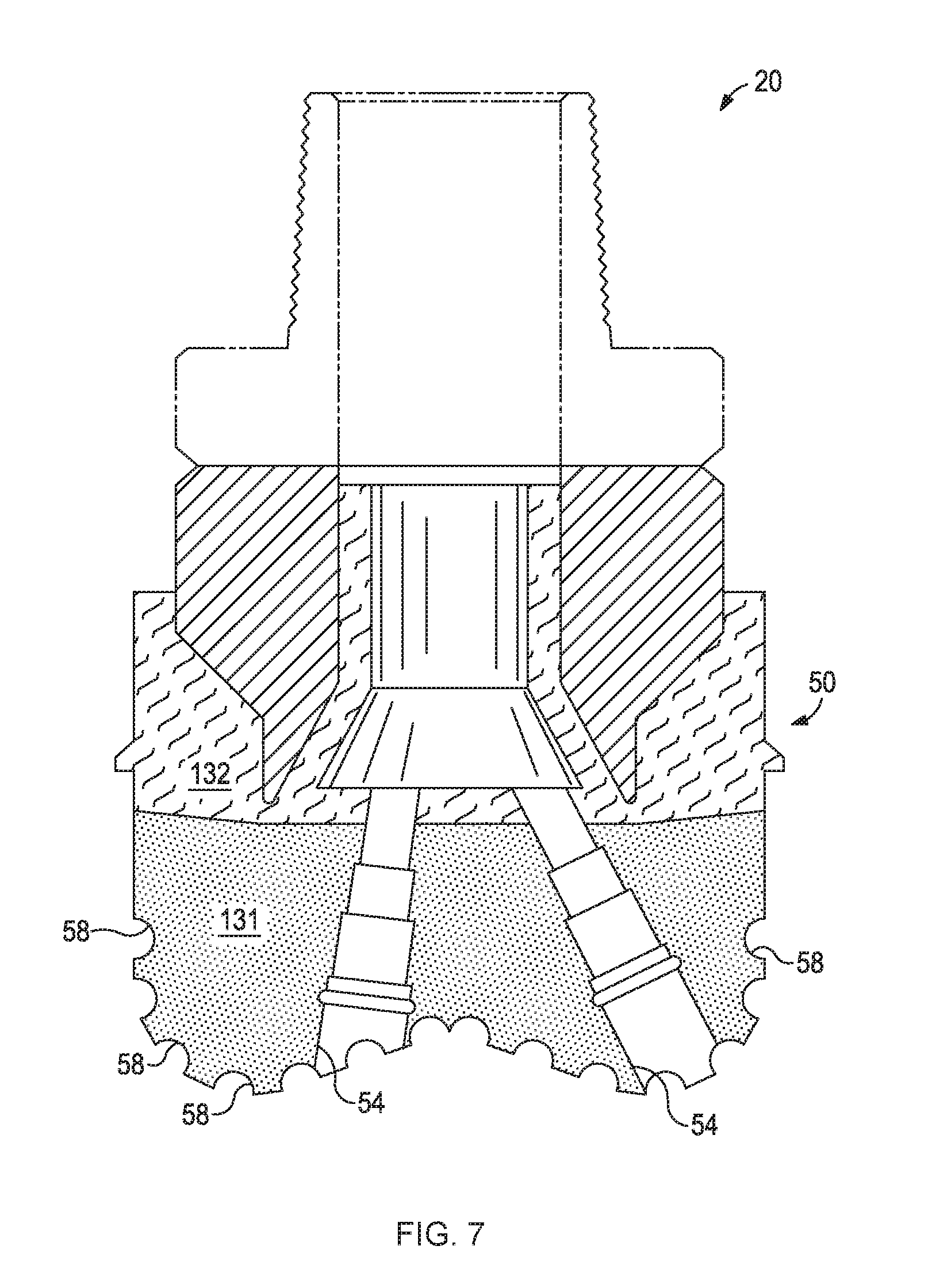
[0072] In another example, FIG. 7 is a cross-sectional view showing one example of a drill bit 20 formed with a bit body 50 having a hard composite portion 132 and a structural MMC portion 131 in accordance with the teachings of the present disclosure. The structural MMC portion 131 is shown to be located proximal to the nozzle openings 54 and the pockets 58.
[0073] In some examples, the configuration of the foam matrix material (e.g., shape, cell type, cell size, cell shape, foam material, and the like) may be different in different portions of the structural MMC 131 to achieve different qualitative results, such as to mitigate crack initiation and propagation, mitigate erosion, and/or minimize the additional cost that may be associated with some foam matrix materials.
[0074] For example, FIG. 8 is a cross-sectional view showing one example of a drill bit 20 formed with a bit body 50 having a structural MMC portion 131 in accordance with the teachings of the present disclosure. The cell size of the foam matrix material decreases or progressively decreases from apex to the shank of the bit body 50 (as illustrated by the degree or concentration of stippling in the bit body 50). As illustrated, the smallest cell sizes of the foam matrix material are adjacent the nozzle openings 54 and the pockets 58 of the structural MMC 131 and the largest cell sizes of the foam matrix material are adjacent the metal blank 36 of the structural MMC 131.
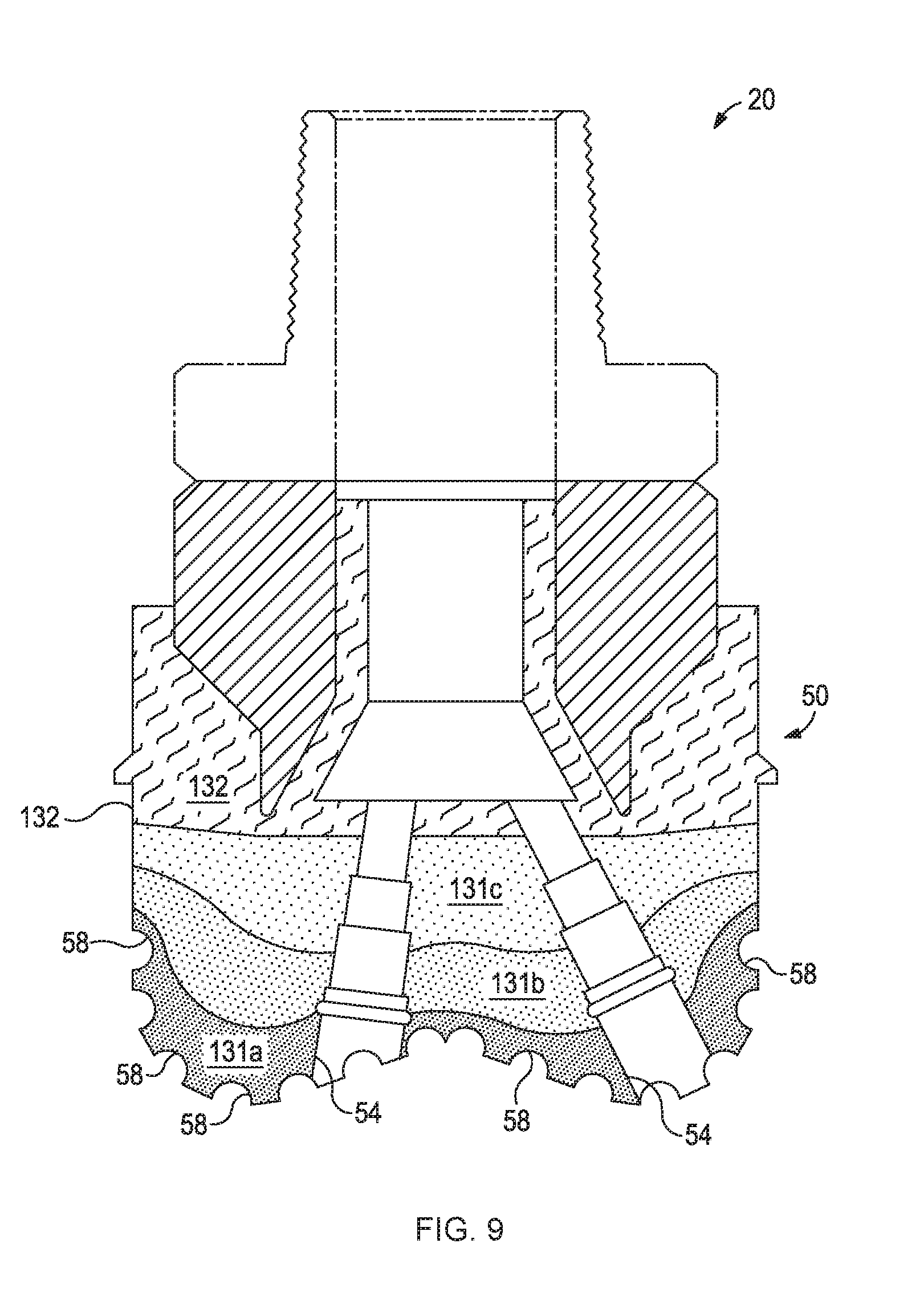
[0075] In some instances, the concentration change of the cell sizes of a foam matrix material (or multiple foam matrix materials) of a structural MMC may be gradual. Alternatively, the concentration change may be more distinct and resemble layering or localization. For example, FIG. 9 is a cross-sectional view showing one example of a drill bit 20 formed with a bit body 50 having a hard composite portion 132 that is not a structural MMC and a structural MMC portion 131 in accordance with the teachings of the present disclosure. The structural MMC portion 131 is shown to be located proximal to the nozzle openings 54 and the pockets 58 in layers 131a, 131b, and 131c. The layer 131a is shown to be located proximal to the nozzle openings 54 and the pockets 58 and may have the smallest cell sizes of a foam matrix material. The layer 131c with the largest cell sizes of a foam matrix material is shown to be located proximal to the hard composite portion 132. The layer 131b with the intermediate cell sizes of the foam matrix material is shown to be disposed between layers 131a and 131c. It is to be appreciated that the layers 131a, 131b, and 131c may be made of the same or different material, and may be a continuous or discontinuous foam matrix material. Alternatively or additionally, the structural MMC 131 portion of layers 131a, 131b, and 131c may vary by the type of material forming the foam matrix material, the cell shape, the cell type, the foam matrix material shape, and the like, without departing from the scope of the present disclosure.
[0076] One skilled in the art would recognize the various configurations and locations for the hard composite portions that are not structural MMCs and the structural MMC portions (including with varying configurations thereof) that would be suitable for producing a particular tool, or wellbore tool, such as a bit body and a resultant drill bit to achieve certain qualities, such as a reduced propensity to have cracks initiate and propagate.
[0077] Further, one skilled in the art would recognize the modifications to the composition of the reinforcement material 130 of FIG. 5 to form a bit body according to the above examples in FIGS. 6-9 and other configurations within the scope of the present disclosure.
[0078] FIG. 10 is a schematic showing one example of a drilling assembly 200 suitable for use in conjunction with the drill bits of the present disclosure. It should be noted that while FIG. 10 generally depicts a land-based drilling assembly, those skilled in the art will readily recognize that the principles described herein are equally applicable to subsea drilling operations that employ floating or sea-based platforms and rigs, without departing from the scope of the disclosure.
[0079] The drilling assembly 200 may include a drilling platform 202 coupled to a drill string 204. The drill string 204 may include, but is not limited to, drill pipe and coiled tubing, as generally known to those skilled in the art. A drill bit 206 according to any of the examples described herein may be attached to the distal end of the drill string 204 and may be driven either by a downhole motor and/or via rotation of the drill string 204 from the well surface. As the drill bit 206 rotates, it creates a wellbore 208 that penetrates the subterranean formation 210. The drilling assembly 200 may also include a pump 212 that circulates a drilling fluid through the drill string (as illustrated as flow arrows C) and other pipes 214.
[0080] One skilled in the art would recognize other equipment suitable for use in conjunction with drilling assembly 200, which may include, but is not limited to, retention pits, mixers, shakers (e.g., shale shaker), centrifuges, hydrocyclones, separators (including magnetic and electrical separators), desilters, desanders, filters (e.g., diatomaceous earth filters), heat exchangers, any fluid reclamation equipment, and the like. Further, the drilling assembly may include one or more sensors, gauges, pumps, compressors, and the like.
[0081] The structural MMC portion comprising foam matrix material infiltrated with a binder material(s) described herein may be implemented in other tools or wellbore tools or portions thereof and systems relating thereto, without departing from the scope of the present disclosure. Examples of such wellbore tools where a structural MMC portion described herein may be implemented in at least a portion thereof may include, but are not limited to, reamers, coring bits, rotary cone drill bits, centralizers, pads used in conjunction with formation evaluation (e.g., in conjunction with logging tools), packers, and the like. In some instances, portions of wellbore tools where a structural MMC described herein may be implemented may include, but are not limited to, wear pads, inlay segments, cutters, fluid ports (e.g., the nozzle openings described herein), convergence points within the wellbore tool (e.g., the apex described herein), and the like, and any combination thereof.
[0082] Examples disclosed herein include:
[0083] Example A: A structural metal-matrix composite (MMC) comprising: a foam matrix material having a cellular structure, the foam matrix material selected from the group consisting of a metallic foam, a ceramic foam, and any combination thereof; a structural element of a tool; and a binder material infiltrated through the cellular structure of the foam matrix material to bind the foam matrix material and the structural element of the tool.
[0084] Example B: A method comprising: placing a foam matrix material in a region of a mold, the foam matrix material having a cellular structure and selected from the group consisting of a metallic foam, a ceramic foam, and any combination thereof; placing a binder material in the mold; placing a structural element of a tool in the mold; heating the mold, the foam matrix material, the binder material, and the structural element of the tool to a temperature above the melting point of the binder material; infiltrating the cellular structure of the foam matrix material with the binder material; and cooling the mold, the foam matrix material, the binder material, and the structural element of the tool, wherein the infiltrated binder material binds the foam matrix material and the structural element of the tool.
[0085] Example C: A drilling assembly comprising: a drill string extendable from a drilling platform and into a wellbore; a drill bit attached to an end of the drill string and including a bit body and a plurality of cutting elements coupled to an exterior portion of the bit body, the bit body composed of a structural metal-matrix composite (MMC) comprising: a foam matrix material having a cellular structure, the foam matrix material selected from the group consisting of a metallic foam, a ceramic foam, and any combination thereof; the bit body; and a binder material infiltrated through the cellular structure of the foam matrix material to bind the foam matrix material and the bit body; and a pump fluidly connected to the drill string and configured to circulate a drilling fluid to the drill bit through the wellbore.
[0086] Exemplary additional elements applicable to A, B, and/or C may include the following in any suitable combination:
[0087] Element 1: Wherein the cellular structure of the foam matrix material is an open-cell foam structure or a closed-cell foam structure.
[0088] Element 2: Wherein the structural MMC further comprises reinforcement particulates.
[0089] Element 3: Wherein the foam matrix material comprises the metallic foam composed of a metallic material selected from the group consisting of a metal, a metal alloy, a metal carbide, a superalloy, and any combination thereof.
[0090] Element 4: Wherein the foam matrix material comprises the ceramic foam composed of a ceramic material selected from the group consisting of an oxide ceramic, a boride ceramic, a nitride ceramic, a silicate ceramic, a carbide ceramic, diamond, and any combination thereof.
[0091] Element 5: Wherein the binder material is at least partially selected from the group consisting of copper, nickel, manganese, zinc, and any combination thereof.
[0092] Element 6: Wherein the structural element of the tool corresponds to a portion of a wellbore tool.
[0093] Element 7: Wherein the structural element of the tool corresponds to a bit body of a drill bit.
[0094] Element 8: Wherein the foam matrix material melts into, dissolves into, diffuses into, or reacts with the binder material during infiltration of the foam matrix material with the binder material, thereby forming a networked ductile phase.
[0095] Element 9: Wherein the foam matrix material reacts with the binder material during infiltration of the foam matrix material with the binder material, thereby forming an intermetallic phase.
[0096] Element 10: Wherein a mold is used to form a structural metal-matrix composite, and the mold corresponds to all or a portion of a wellbore tool mold.
[0097] Element 11: Wherein a mold is used to form a structural metal-matrix composite, wherein the mold corresponds to all or a portion of a drill bit.
[0098] Element 12: Wherein a mold is used to form a structural metal-matrix composite, wherein the mold corresponds to a bit body of a drill bit.
[0099] By way of non-limiting example, exemplary combinations applicable to A, B, and C include: 1-12; 1, 3, and 10; 4, 5, 7, and 12; 8 and 9; 2, 4, 11, and 12; 6 and 7; 8, 9, and 11; and the like.
[0100] One or more illustrative examples are presented herein. Not all features of a physical implementation are described or shown in this application for the sake of clarity. It is understood that in the development of a physical embodiment incorporating the examples described herein, numerous implementation-specific decisions must be made to achieve the developer's goals, such as compliance with system-related, business-related, government-related and other constraints, which vary by implementation and from time to time. While a developer's efforts might be time-consuming, such efforts would be, nevertheless, a routine undertaking for those of ordinary skill in the art and having benefit of this disclosure.
[0101] Therefore, the present disclosure is well adapted to attain the ends and advantages mentioned as well as those that are inherent therein. The particular examples disclosed above are illustrative only, as the present disclosure may be modified and practiced in different but equivalent manners apparent to those skilled in the art having the benefit of the teachings herein. Furthermore, no limitations are intended to the details of construction or design herein shown, other than as described in the claims below. It is therefore evident that the particular illustrative examples disclosed above may be altered, combined, or modified and all such variations are considered within the scope and spirit of the present disclosure. The examples illustratively disclosed herein suitably may be practiced in the absence of any element that is not specifically disclosed herein and/or any optional element disclosed herein. While compositions and methods are described in terms of "comprising," "containing," or "including" various components or steps, the compositions and methods can also "consist essentially of" or "consist of" the various components and steps. Also, the terms in the claims have their plain, ordinary meaning unless otherwise explicitly and clearly defined by the patentee. Moreover, the indefinite articles "a" or "an," as used in the claims, are defined herein to mean one or more than one of the element that it introduces. If there is any conflict in the usages of a word or term in this specification and one or more patent or other documents that may be incorporated herein by reference, the definitions that are consistent with this specification should be adopted.
* * * * *
D00000
D00001
D00002
D00003
D00004
D00005
D00006
D00007
D00008
D00009
D00010
XML
uspto.report is an independent third-party trademark research tool that is not affiliated, endorsed, or sponsored by the United States Patent and Trademark Office (USPTO) or any other governmental organization. The information provided by uspto.report is based on publicly available data at the time of writing and is intended for informational purposes only.
While we strive to provide accurate and up-to-date information, we do not guarantee the accuracy, completeness, reliability, or suitability of the information displayed on this site. The use of this site is at your own risk. Any reliance you place on such information is therefore strictly at your own risk.
All official trademark data, including owner information, should be verified by visiting the official USPTO website at www.uspto.gov. This site is not intended to replace professional legal advice and should not be used as a substitute for consulting with a legal professional who is knowledgeable about trademark law.