Snowplowable Pavement Marker
Lowe; Harry E.
U.S. patent application number 16/258253 was filed with the patent office on 2019-08-01 for snowplowable pavement marker. The applicant listed for this patent is Harry E. Lowe. Invention is credited to Harry E. Lowe.
| Application Number | 20190234032 16/258253 |
| Document ID | / |
| Family ID | 65411948 |
| Filed Date | 2019-08-01 |


| United States Patent Application | 20190234032 |
| Kind Code | A1 |
| Lowe; Harry E. | August 1, 2019 |
Snowplowable Pavement Marker
Abstract
Disclosed are improved snowplowable pavement markers held fixedly to a roadway by adhesive. The markers include a holder and at least one transversely arranged reflector to retroreflect incident light from headlights of approaching vehicles. The holders have a pocket for supporting the reflector. One or more through openings having angled sides are defined in the bottom of the pocket so that when the marker is installed in an adhesive bed on the pavement, adhesive flows into contact with the holder and the bottom of the reflector to simultaneously affix both to the pavement. Reflectors may be replaced by simply chiseling an old reflector out of the holder pocket to create a flat bottom surface in the pocket to which a bead of mastic adhesive is applied and a new reflector is subsequently installed. This new marker construction applies to both raised and recessed snowplowable pavement markers.
| Inventors: | Lowe; Harry E.; (Schaumburg, IL) | ||||||||||
| Applicant: |
|
||||||||||
|---|---|---|---|---|---|---|---|---|---|---|---|
| Family ID: | 65411948 | ||||||||||
| Appl. No.: | 16/258253 | ||||||||||
| Filed: | January 25, 2019 |
Related U.S. Patent Documents
| Application Number | Filing Date | Patent Number | ||
|---|---|---|---|---|
| 62622918 | Jan 28, 2018 | |||
| Current U.S. Class: | 1/1 |
| Current CPC Class: | E01F 9/578 20160201; E01F 9/512 20160201; E01F 9/553 20160201; E01F 11/00 20130101 |
| International Class: | E01F 9/553 20060101 E01F009/553; E01F 9/576 20060101 E01F009/576; E01F 11/00 20060101 E01F011/00 |
Claims
1. A reflective pavement marker to be held fixedly to a roadway by adhesive, the marker comprising: a reflector for reflecting incident light; a holder having upwardly-extending walls forming an upwardly-opening pocket; the reflector being at least partially seated within the pocket; the holder having an opening with sides extending from the bottom of the holder to the pocket; and, whereby adhesive extending through the opening holds the reflector within the holder.
2. The reflective pavement marker of claim 1 wherein the sides of the opening at least partially extend upwardly and radially outward from the bottom of the holder.
3. The reflective pavement marker of claim 1 wherein the holder has a shoulder with an upwardly-facing horizontal surface outward of the opening underlying the reflector seated within the pocket.
4. The reflective pavement marker of claim 3 further including a vent in the shoulder providing air relief past the reflector seated within the pocket.
5. The reflective pavement marker of claim 3 wherein the shoulder is intermediate the top and bottom of the holder and the sides of the opening below the shoulder extend upwardly and radially outward from the bottom of the holder.
6. The reflective pavement marker of claim 1 wherein the reflector is generally rectangular and wherein the walls of the holder include laterally-spaced end walls and axially-spaced side walls around the pocket generally corresponding to the shape and size of the reflector such that the reflector may be seated at least partially in the pocket.
7. The reflective pavement marker of claim 6 wherein the holder has a shoulder with an upwardly-facing horizontal surface outward of the opening underlying the reflector seated within the pocket.
8. The reflective pavement marker of claim 7 further including a vent in the shoulder providing air relief past the reflector seated within the pocket.
9. The reflective pavement marker of claim 1 wherein the holder is comprised of metal and includes a pair of laterally-spaced, longitudinal keels and a cross member connecting the keels forming at least a portion of the pocket.
10. The reflective pavement marker of claim 1 wherein the holder is comprised of plastic and wherein the walls of the holder include a pair of axially-spaced end walls and a pair of laterally-spaced side walls forming at least a portion of the pocket.
11. The reflective pavement marker of claim 1 wherein the reflector and the holder are non-integral separate components of the marker and adhesive applied to the roadway passing through the opening holds the reflector within the holder and fixes both the holder and the reflector to the roadway.
12. A method of fixing the reflective pavement marker of claim 1 to a roadway, the method comprising: creating a cavity in a roadway of a dimension allowing the marker to be at least partially seated therein; at least partially filling the cavity with adhesive; and, positioning the marker at least partially in the cavity in contact with the adhesive such that the adhesive passes through the opening and flows into bonding contact with the holder and with the reflector.
13. A reflective pavement marker to be held fixedly to a roadway by adhesive, the marker comprising: a reflector for reflecting incident light; a holder having upwardly-extending walls forming an upwardly-opening pocket; the reflector being at least partially seated within the pocket; the holder having an opening with sides extending from the bottom of the holder to the pocket; the sides of the opening at least partially extending upwardly and radially outward; the holder having a shoulder with an upwardly-facing horizontal surface outward of the opening underlying the reflector seated within the pocket; a vent in the shoulder providing air relief past the reflector seated within the pocket; and, whereby adhesive extending through the opening holds the reflector within the holder.
14. The reflective pavement marker of claim 12 wherein the holder is comprised of metal and includes a pair of laterally-spaced, longitudinal keels and a cross member connecting the keels forming at least a portion of the pocket.
15. The reflective pavement marker of claim 11 wherein the holder is comprised of plastic and wherein the walls of the holder include a pair of axially-spaced end walls and a pair of laterally-spaced side walls forming at least a portion of the pocket.
16. The reflective pavement marker of claim 1 wherein the reflector and the holder are non-integral separate components of the marker and adhesive applied to the roadway passing through the opening holds the reflector within the holder and fixes both the holder and the reflector to the roadway.
Description
CROSS REFERENCE TO RELATED APPLICATION
[0001] This application claims the benefit of and priority from U.S. Provisional Application Ser. No. 62/622,918 filed 28 Jan. 2018 (Jan. 28, 2018), the disclosures of which are herein incorporated by reference in their entireties.
BACKGROUND OF THE INVENTION
Technical Field
[0002] The present invention relates to reflectors and, more particularly, to snowplowable pavement markers.
Background Art
[0003] Pavement markers provide visible delineation of center lines, edge lines, turning lanes, ramps, and the like. Pavement markers must withstand damage from vehicle traffic, snowplows, and sundry environmental factors. Presently, two types of snowplowable pavement markers are generally being used, namely, raised markers and recessed markers.
[0004] A typical raised marker utilizes a heavy iron casting embedded within a pavement cutout. The casting has raised laterally spaced inclined longitudinal keels or rails, and a reflector held between and at a lower height than the rails. While the casting is embedded in the pavement, both the rails and reflector protrude slightly above the pavement surface. Raised markers have been used extensively in snow-belt states, as the rails effectively guide the snowplow up and over the reflector. However, many raised marker castings are often dislodged from the pavement, which then potentially become heavy projectiles capable of causing both vehicle damage and personal injury. In fact, some states have already demanded increased inspection of raised markers and/or their removal.
[0005] Recessed markers, which are being increasingly specified in highway construction, are mounted below the pavement surface in long narrow line-of-sight grooves that allow vehicle headlight rays to illuminate the reflector. Recessed markers typically have reflector assemblies that are held in plastic holders. The plastic holders are positioned in the grooves and fixed to the roadway pavement by epoxy or other suitable adhesive.
[0006] Raised snowplowable markers using cast iron metal holders, introduced commercially in 1976, were the forerunner of present day designs. Then and now, the reflector predominantly used in raised and recessed snowplowable markers has an integral butyl rubber pad coated with pressure sensitive adhesive as its bottom surface.
[0007] In general, use of the reflector's butyl pad alone for adherence to the reflector holder was long ago (circa 1980) found insufficient and an additional mastic type adhesive was applied to the metal holder, and more recently, to the recessed plastic holder.
[0008] In particular, even with the additional use of mastic type secondary adhesive, the bond between the reflector and the iron holder is tenuous. In a 2 to 4 year period, water penetration under the butyl-type pad causes continuing interfacial rusting and subsequent release of the reflector from the holder. The iron holder disclosed herein illustrates a solution to these problems by providing a tough, non-rusting, structural adhesive surface in the holder for initial and future bonding of the reflector to the holder.
[0009] With roadway exposure, reflectors and the holders in which they are mounted can become detached from roadway pavement. This may be because of weather, environmental conditions and frequent vehicle impacts. As a result, reflectors and/or holders periodically require replacement.
BRIEF SUMMARY OF THE INVENTION
[0010] The present invention is directed to overcoming one or more of the problems as set forth above.
[0011] It is one object of the present invention to provide a roadway marker that is easy to install, replace and is durable.
[0012] It is a further object of the present invention to provide a roadway marker that is effective, strong and inexpensive.
[0013] It is a further object of the present invention to reduce material cost, reduce manufacturing complexities, and eliminate unnecessary components.
[0014] It is an object to provide a marker that is fixed to a roadway with adhesive comprising a holder and a reflector wherein the holder has a bottom through opening permitting adhesive to directly adhere the holder and reflector to the roadway.
[0015] It is also an object to provide a marker wherein the holder opening has angled internal walls so that the adhesive functions to positively secure the holder to the roadway.
[0016] In an exemplary embodiment, the holder is a metal casting with spaced keels and a central connecting portion defining a pocket sized and configured to receive a reflector within the pocket and having an opening through the bottom of the pocket.
[0017] In another exemplary embodiment, the holder is a thin, rectangular, plastic container having a pocket sized and configured to receive a reflector within the pocket and having an opening through the bottom of the pocket.
[0018] In one aspect of the invention, a roadway marker has a reflector and a holder with an opening formed in the bottom permitting epoxy or other adhesive to flow into the interior of the holder and into contact with the reflector.
[0019] In another aspect of the invention, the opening is circumscribed by a tapered wall so that epoxy or other adhesive can flow onto the taper and positively lock the holder and reflector down to the pavement.
[0020] In yet another aspect of the invention, the holder opening is dimensionally smaller than the pocket to define a shoulder for supporting the reflector.
BRIEF DESCRIPTION OF THE SEVERAL VIEWS OF THE DRAWINGS
[0021] The details of construction and operation of the invention are more fully described with reference to the accompanying drawings which form a part hereof and in which like reference numerals refer to like parts throughout.
[0022] In the drawings:
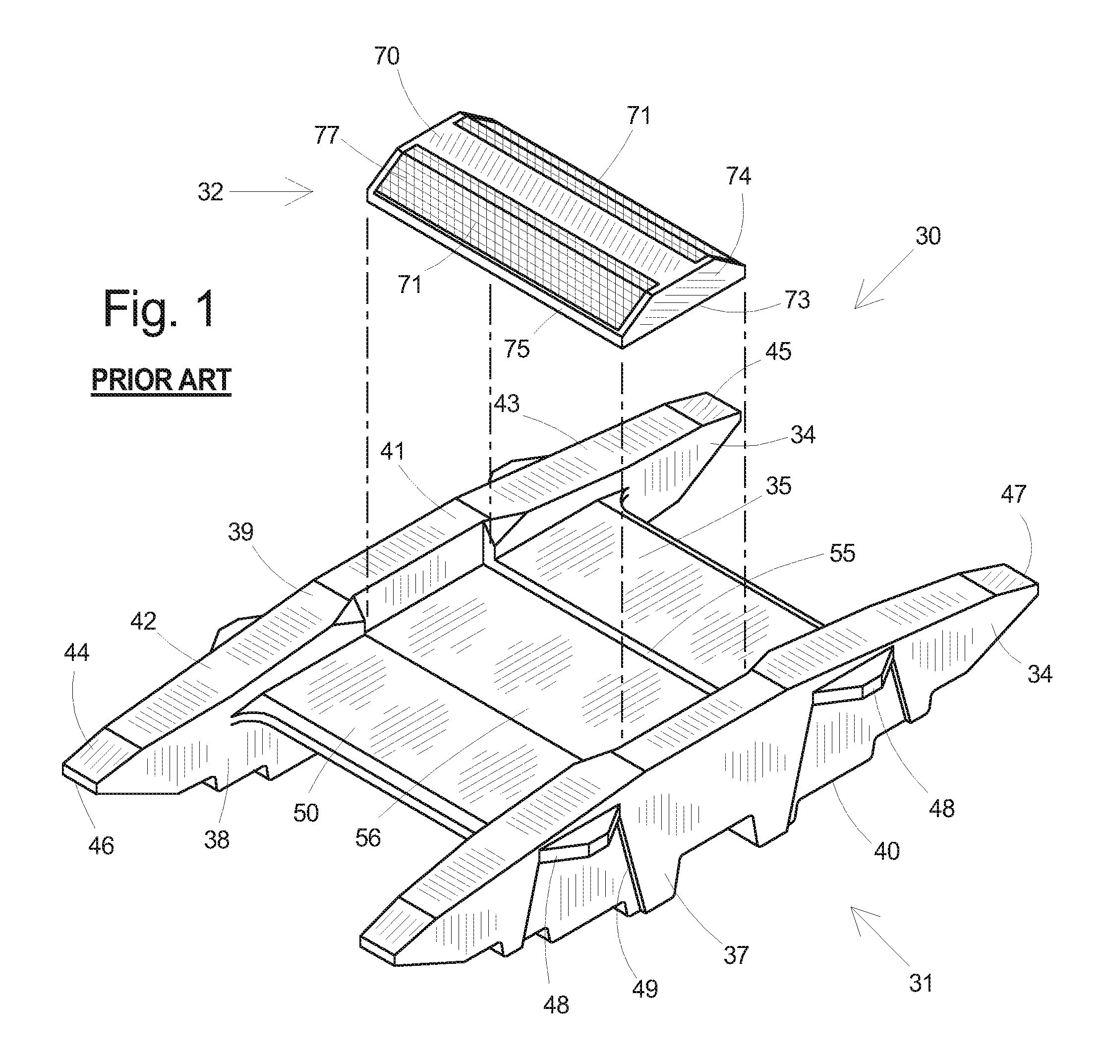
[0023] FIG. 1 is an exploded perspective view of a prior art marker having a metal holder with a closed pocket and a reflector;
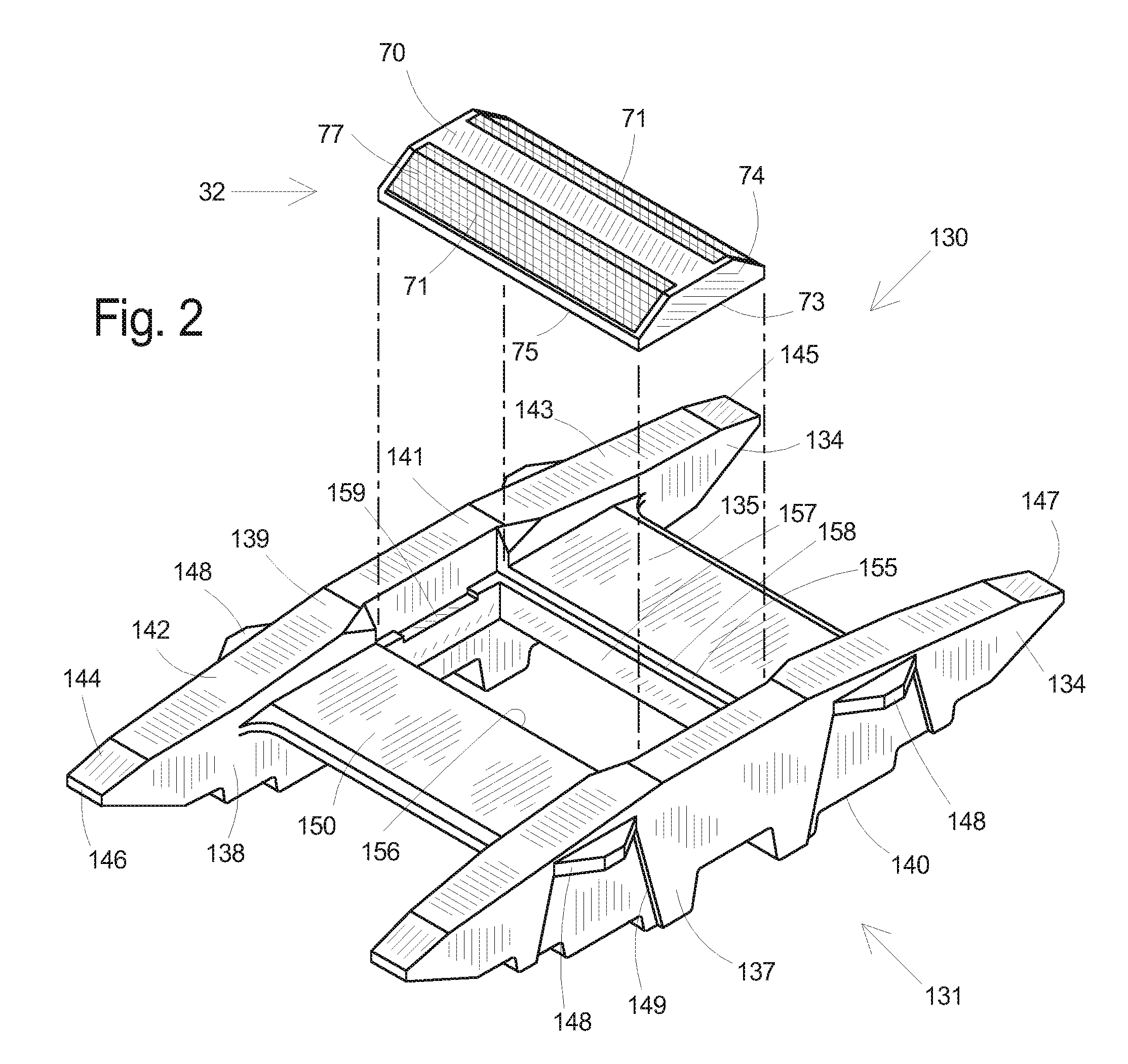
[0024] FIG. 2 is an exploded perspective view of a first embodiment of a marker having a metal holder with a bottom opening and a reflector;
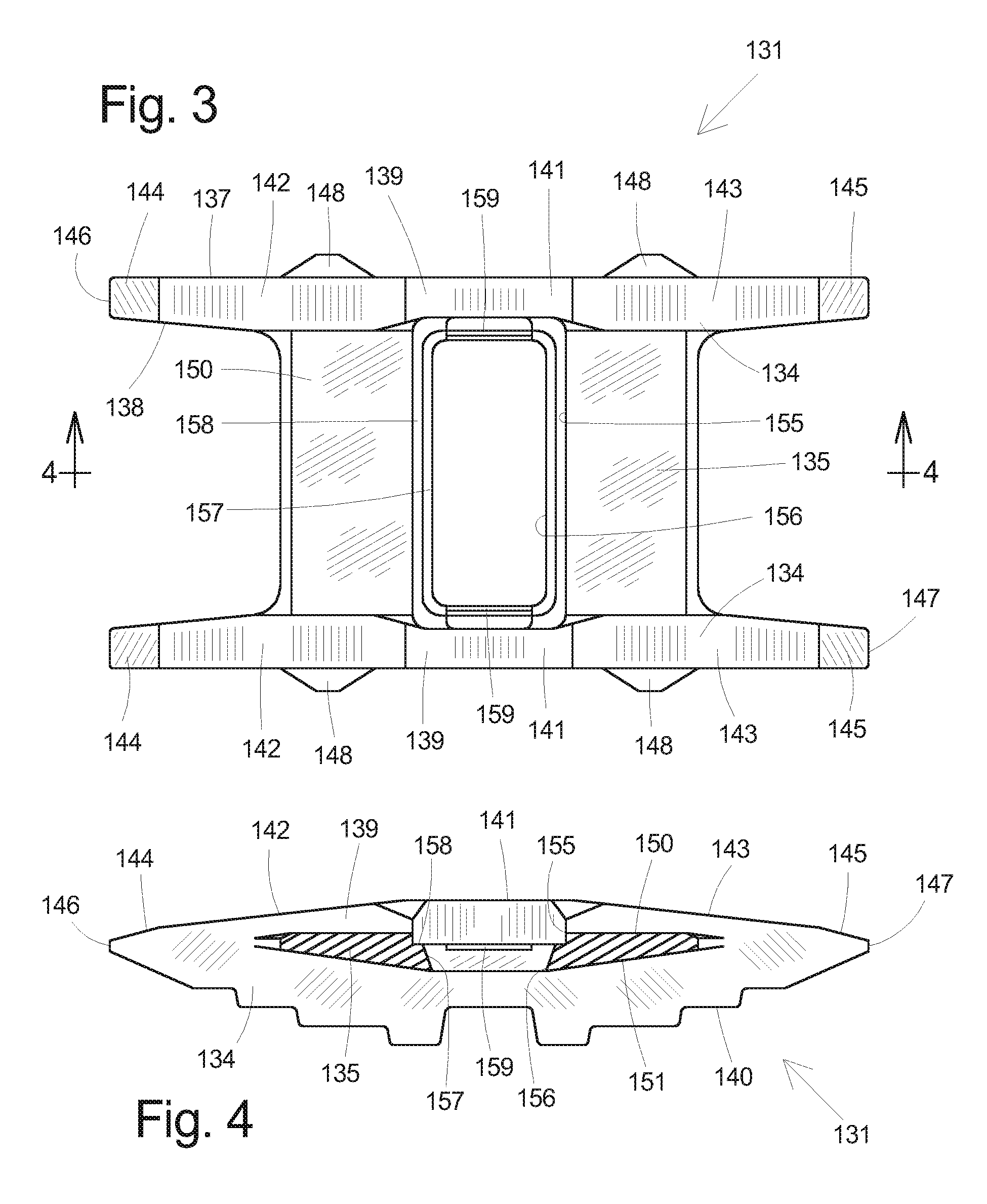
[0025] FIG. 3 is a top plan view of the metal holder shown in FIG. 2;
[0026] FIG. 4 is a vertical cross-sectional view of the metal holder taken along line 4-4 of FIG. 3;
[0027] FIG. 5 is an exploded perspective view of a second embodiment of a marker having a plastic holder with a bottom opening and a reflector;
[0028] FIG. 6 is a top plan view of the plastic holder shown in FIG. 5;
[0029] FIG. 7 is a vertical cross-sectional view of the plastic holder taken along line 7-7 of FIG. 6;
[0030] FIG. 8 is a vertical cross-sectional view of the plastic holder taken along line 8-8 of FIG. 6;
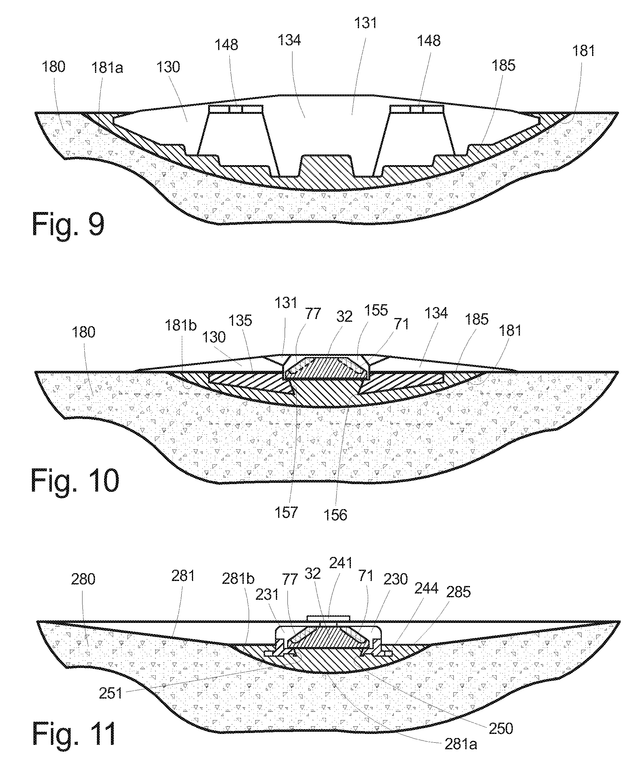
[0031] FIG. 9 is a vertical cross-sectional view of the marker shown in FIG. 2 and a portion of roadway in which it is installed taken along one side of the metal holder;
[0032] FIG. 10 is a vertical cross-sectional view of the marker shown in FIG. 2 and a portion of roadway in which it is installed taken through the center of the metal holder; and,
[0033] FIG. 11 is a vertical cross-sectional view of the marker shown in FIG. 5 and a portion of roadway in which it is installed taken through the center of the plastic holder.
[0034] All figures are drawn for ease of explanation of the basic teachings of the present invention only; the extensions of the figures with respect to number, position, relationship, and dimensions of the parts to form the preferred embodiment will be explained or will be within the skill of the art after the following teachings of the present invention have been read and understood.
DETAILED DESCRIPTION OF THE PREFERRED EMBODIMENTS
[0035] While the present invention is susceptible of embodiment in many different forms, there are shown in the drawings and will be described herein in detail specific embodiments thereof with the understanding that the present disclosure is to be considered as an exemplification of the principles of the invention and is not intended to limit the invention to the specific embodiments illustrated.
[0036] In FIG. 1, a prior art raised roadway marker, generally designated 30, is seen to be comprised of a metal holder, generally designated 31, and a reflector, generally designated 32. The holder 31, which may be integrally formed as a metal casting, typically iron, is bilaterally symmetrical and includes a pair of longitudinally-extending, laterally-spaced rails, or keels 34, connected by a supporting cross member 35.
[0037] Each keel 34 has an outer side wall 37, an inner side wall 38, a top wall 39, and a stepped convex bottom wall 40. The top wall 39 includes a flat top surface 41, forward and rearward ramp surfaces 42 and 43, and forward and rearward inclined surfaces 44 and 45 adjacent the keel ends 46 and 47. A pair of positioning tabs 48, or projecting sponsons, extend outward from the outer side wall 37 at the top of tapering grooves 49.
[0038] The cross member 35 has a relatively flat top surface 50 and an arcuate bottom surface (not shown). Formed in the top surface 50 is a downwardly-extending, generally rectangularly shaped pocket 55 having a planar floor 56 that extends laterally into the side walls 38.
[0039] The reflector 32 comprises a plastic body 70 and one or more retroreflective lenses 71. The reflector body 70 has an attached butyl elastomeric adhesive pad 73 at the bottom, trapezoidal high lateral end walls 74, and low axial walls 75 defining recesses in which the retroreflective lenses 71 are mounted.
[0040] The angularly-mounted retroreflective lenses 71 typically include a flat lens 77 on the exposed obverse face sealing a series of cells each having an array of microprismatic cube elements, or triple mirror corner reflectors, internally disposed along the reverse face. Reflector assemblies of the type described here are commercially available from Ennis-Flint, Inc. of Thomasville, N.C., and from 3M Company's Traffic Safety and Security Division of St. Paul, Minn.,
[0041] In FIGS. 2-4, an improved raised roadway marker, generally designated 30, is seen to be comprised of a metal holder, generally designated 131, and a reflector 32. The reflector 32 is of the type described above.
[0042] The holder 131 may be integrally formed as a single metal casting approximately 10 inches long, 1.9 inches high, and 5.75 inches wide. The casting, which is typically made of iron and is bilaterally symmetrical, includes a pair of longitudinally-extending, laterally-spaced rails, or keels 134, connected by a transverse supporting cross member 135. Each keel 134 has an outer side wall 137, an inner side wall 138, a top wall 139 and a stepped convex bottom wall 140. The top wall 139 includes a flat top surface 141, forward and rearward ramp surfaces 142 and 143, and forward and rearward inclined surfaces 144 and 145 adjacent the keel ends 146 and 147. A pair of positioning tabs 148 extend outward from the outer side wall 137 at the top of tapering grooves 149.
[0043] The cross member 135 has a relatively flat top surface 150 and an arcuate bottom surface 151. Extending vertically into the cross member 135 between the top and bottom surfaces 150 and 151 is a generally rectangular pocket 155 with a through opening 156 circumscribed by the slanting faces of the inwardly projecting internal walls 157. The internal walls 157 define an internal shoulder 158 having an upwardly-facing horizontal surface transverse to the internal walls 157 that supports the bottom edges of the reflector 32 when it is located within the pocket 155. The sides of the opening 156 slant upwardly and radially outward such that the opening 156 has a cross-sectional area at its top end that is dimensionally larger than the cross-sectional area at its bottom end. An air vent 159 is formed along the top edge of the internal wall 157 at each side thereof. Additional vents may be formed around any side surface of the internal shoulder. The pocket 155 defining the shoulder 158 and opening 156 may extend laterally into the keel 134 as shown in FIGS. 2 and 3.
[0044] As seen in FIG. 2, the reflector 32 is located within the pocket 155 with the bottom edges of the reflector 32 located on the shoulder 158. The reflector 32 is of the type described above and comprises a plastic body 70 and one or more retroreflective lenses 71. The reflector body 70 has an attached butyl elastomeric adhesive pad 73, trapezoidal high lateral end walls 74, and low axial walls 75 defining recessed transverse faces on which the retroreflective lenses 71 are mounted.
[0045] The retroreflective lenses 71 are mounted within the reflector 32 so that the lens face 77 is tilted about 30.degree. relative to the bottom surface. While an angle of 30.degree. relative to the roadway is preferred, this may be modified up to plus 20.degree.. The retroreflective lenses 71 may be colored white, yellow, red, blue or green. In some installations, where the marker 130 is to be seen from opposite directions, two retroreflective lenses 71 are used. Herein, a reflector refers to an assembly of one or more retroreflective lenses and a retroreflector refers to an assembly of one or more smaller elements that reflect light back in the direction of incident light.
[0046] The reflector 32 described hereabove formed separately from the holder is approximately 2 inches long and 4 inches wide and is made of polycarbonate ("PC"). The adhesive coated elastomeric pad 73 is permanently factory bonded to the bottom of the reflector 32 to temporarily affix it to the holder 131 before installation of the marker 130 in the roadway.
[0047] As seen in FIGS. 9 and 10, the marker 130 is shown positioned in a section of pavement 180. To install the marker 130, an arcuate cavity 181 having an H-shaped cross-section is cut into the pavement 180. The laterally-spaced sections of the groove 181a are cut to a depth sufficient to receive the keels 134, while the middle section 181b is cut to a shallower depth sufficient to receive the cross member 135. Typically, this is done with a 3-part circular diamond blade arrangement. The blades for the narrow cuts have a diameter of 20 inches and the wider cut inner blades have a diameter of 18 inches, the large-diameter cut being about 1.5-2.0 inches deep.
[0048] Adhesive 185 is poured into the cavity 181 and the marker 130 is set into place. The marker 130 is pressed into the cavity 181 until the positioning tabs 148 rest on the adjacent uncut pavement surface with the keel 134 positioned just above the cavity bottom (FIG. 9). The adhesive 185 flows around the keel ends (FIG. 10), against the keels 134 and the arcuate bottom of the cross member 135, and through the pocket opening 156 into contact with the bottom of the reflector 32. The marker 130 will thereby be securely held therein when the adhesive 185 cures.
[0049] In FIGS. 5-8, a recessed roadway marker, generally designated 230, is shown and is seen to include a plastic holder, generally designated 231, and a reflector 32 of the type previously described above. The reflector holder 231, which might be of unitary construction, has an upwardly facing recess, or pocket 233, defined by a peripheral shoulder 234 with a horizontal upwardly-facing surface 235, a pair of axially-spaced short end walls 236 and 237, and a pair of laterally-spaced, transverse, elevated side walls 238 and 239. Positioning tabs 241 and 242 project outwardly from the upper portion of the side walls 238 and 239. The tabs 241 and 242 might be narrower at the top of the side wall 238 and 239 to easily break away without dislocation of the marker 230. Holder anchoring means or tabs 244 project outwardly away from the lower portions of the axial end walls 236 and 237 outside the pocket 233. The anchoring means 244 may be comprised of many separate spaced apart projections extending off the holder 231 as shown or may be a single projecting flange extending across the entire width of each axial end wall.
[0050] Defined through the bottom 248 is a rectangular through opening 250. The top of the opening 250 is dimensionally larger than the bottom of the opening 250 so that the slanting faces of the internal side wall 251 of the opening 250 are angled approximately 20.degree. relative to vertical. A cutout is formed in the shoulder 234 at the lateral sides to create shallow air relief vents 255. It is understood that a plurality of openings may be substituted for a single opening and openings may be of differing size and have side surfaces of differing angles.
[0051] As seen in FIG. 11, the recessed marker 230 is shown positioned in a section of pavement 280. To install the marker 230, a long line-of-sight groove 281 is cut longitudinally in the pavement 280 starting at zero depth where the groove 281 begins and ends and extending progressively to a deepest medial portion 281a, such as where the one or more markers might be secured. The line-of-sight groove 281 may have a length of 9 feet or longer. At the point where the marker or markers 230 will be located, a deeper, shorter secondary groove, or cavity 281b, is cut sufficiently deep to mount the marker 230 therein allowing the marker 230 to have a top clearance below the adjacent uncut pavement surface. The arcuate secondary groove 281b is slightly wider than the width of the holder 231.
[0052] An epoxy adhesive 285 or other adhesive (hereinafter the term "adhesive" shall mean to include any effective or suitable adhesive) is poured into the secondary groove 281b and the marker 230 is set into place. The marker 230 is pressed into the concave secondary groove 281b until the positioning tabs 241 and 242 rest on the adjacent uncut pavement surface 280. This accurately locates the marker 230 vertically relative to the pavement surface. The adhesive 285 flows around and over the anchoring tabs 244 and also up through the pocket opening 250 and tapered internal side walls 251 of the holder 231 into contact with the bottom of the reflector 32. The reflector 32 will then be securely held therein when the adhesive 285 cures and bonds to the butyl pad.
[0053] It is noted that the adhesive is a structural or engineering adhesive that includes epoxies, polyesters, polyurethanes, acrylics, and the like.
[0054] Note that when installed, the high side walls 238 and 239 are situated below the level of the pavement where they will not be impacted by vehicular traffic or snowplows. Similarly, the low axially-spaced end walls 236 and 237 are at a level relative to the bottom of the reflective lenses 71 or such that the axially-spaced end walls 236 and 237 do not block the line-of-sight from vehicles to the reflective lenses 71.
[0055] Whenever a reflector as disclosed herein needs to be replaced because it is worn or broken, it can be chiseled or pried out of the holder. After the pocket surface is cleaned or otherwise prepared by removing residual adhesive and other contaminants, new adhesive is applied and a new reflector is pressed down into the adhesive forcing it to flow onto all surfaces and around corners and edges to bond the reflector to the holder.
INDUSTRIAL APPLICABILITY
[0056] From the foregoing, it will be observed that numerous variations and modifications may be effected without departing from the spirit and scope of the invention. It will also be observed that the various elements of the invention may be in any number of combinations, and that all of the combinations are not enumerated here. It will be understood that no limitation with respect to the specific apparatus illustrated herein is intended or should be inferred. While specific embodiments of the invention have been disclosed, one of ordinary skill in the art will recognize that one can modify the materials, dimensions and particulars of the embodiments without straying from the inventive concept.
[0057] Other aspects, objects and advantages of this invention can be obtained from a study of the drawings and the foregoing disclosure.
[0058] It should be understood that the terms "top," "bottom," "forward," "rear," "rearward," "upper," "lower," "inner," "outer," "side," "lateral," "end," "height," "width," "length," "horizontal," "vertical," and similar terms as used herein, have reference only to the structure shown in the drawings and are utilized only to facilitate describing the invention. The terms and expressions employed herein have been used as terms of description and not of limitation.
[0059] As used herein, the term "within" shall mean "to be partially or completely inside of"; the term "axial" refers to a direction that is longitudinal and substantially straight; the term "transverse" refers to a direction other than the axial direction (e.g., orthogonal or nonorthogonal).
* * * * *
D00000
D00001
D00002
D00003
D00004
D00005
XML
uspto.report is an independent third-party trademark research tool that is not affiliated, endorsed, or sponsored by the United States Patent and Trademark Office (USPTO) or any other governmental organization. The information provided by uspto.report is based on publicly available data at the time of writing and is intended for informational purposes only.
While we strive to provide accurate and up-to-date information, we do not guarantee the accuracy, completeness, reliability, or suitability of the information displayed on this site. The use of this site is at your own risk. Any reliance you place on such information is therefore strictly at your own risk.
All official trademark data, including owner information, should be verified by visiting the official USPTO website at www.uspto.gov. This site is not intended to replace professional legal advice and should not be used as a substitute for consulting with a legal professional who is knowledgeable about trademark law.