Oxidation Fiber Manufacturing Method
WANG; CHIH-YUNG
U.S. patent application number 15/951341 was filed with the patent office on 2019-08-01 for oxidation fiber manufacturing method. The applicant listed for this patent is UHT UNITECH COMPANY LTD.. Invention is credited to CHIH-YUNG WANG.
| Application Number | 20190233977 15/951341 |
| Document ID | / |
| Family ID | 62116203 |
| Filed Date | 2019-08-01 |


View All Diagrams
| United States Patent Application | 20190233977 |
| Kind Code | A1 |
| WANG; CHIH-YUNG | August 1, 2019 |
OXIDATION FIBER MANUFACTURING METHOD
Abstract
The present disclosure mainly uses a transmitting unit to drive the fiber yarn bunch to pass an operation region of the microwave processing unit, and the microwave is focused to perform an ultra-fast pre-oxidization process on the passed fiber yarn bunch, thus processing the fiber yarn bunch to form an oxidation fiber yarn bunch. Not only an oxidization time of an oxidation fiber can be reduced, but also the cross section area of the oxidation layer of the oxidation fiber in the oxidation fiber yarn bunch generated by the microwave focusing oxidization process occupies more than 50% of the cross section area of the oxidation fiber in the oxidation fiber yarn bunch. Thus, the shell-core structure of the oxidation fiber can be reduced efficiently. Even, the oxidation fiber has no obvious shell-core structure. Accordingly, relatively positive and reliable means for increasing the performance of carbon fiber are provided.
| Inventors: | WANG; CHIH-YUNG; (TAOYUAN CITY, TW) | ||||||||||
| Applicant: |
|
||||||||||
|---|---|---|---|---|---|---|---|---|---|---|---|
| Family ID: | 62116203 | ||||||||||
| Appl. No.: | 15/951341 | ||||||||||
| Filed: | April 12, 2018 |
| Current U.S. Class: | 1/1 |
| Current CPC Class: | D01F 9/225 20130101; D01F 9/14 20130101; D01F 11/16 20130101; D01F 9/32 20130101; D10B 2321/10 20130101; D10B 2401/063 20130101; D10B 2211/04 20130101; D01D 10/0454 20130101; D10B 2101/12 20130101; D01F 9/18 20130101 |
| International Class: | D01F 11/16 20060101 D01F011/16; D01D 10/04 20060101 D01D010/04; D01F 9/18 20060101 D01F009/18; D01F 9/32 20060101 D01F009/32 |
Foreign Application Data
| Date | Code | Application Number |
|---|---|---|
| Jan 29, 2018 | TW | 107103128 |
Claims
1. An oxidation fiber manufacturing method, used to pre-oxidize a fiber yarn bunch to form an oxidation fiber yarn bunch; the fiber yarn bunch is formed by merely one fiber, or alternatively, the fiber yarn bunch is formed by binding a plurality of fibers; the oxidation fiber yarn bunch is formed by merely one oxidation fiber, or alternatively, the oxidation fiber yarn bunch is formed by binding a plurality of oxidation fibers; the oxidation fiber manufacturing method comprises following steps: a yarn bunch providing step: preparing the fiber yarn bunch; and a microwave processing step: exposing the fiber yarn bunch in a microwaving condition to form the oxidation fiber yarn bunch.
2. The oxidation fiber manufacturing method according to claim 1, wherein the microwaving condition comprises: a microwave frequency being 300 MHz through 300,000 MHz; a microwave power being 1 kW/m.sup.2 through 1000 kW/m.sup.2 ; an operation temperature being 100.degree. C. through 600.degree. C.; a processing time being 1 minute through 40 minutes; and a gas atmosphere being at least one of oxygen, air and ozone.
3. The oxidation fiber manufacturing method according to claim 2, wherein the microwave power is 10 kW/m.sup.2 through 24 kW/m.sup.2 .
4. The oxidation fiber manufacturing method according to claim 2, wherein the microwave frequency is 2000 MHz through 3000 MHz, the operation temperature being 150.degree. C. through 350.degree. C., and the processing time is 5 minutes through 20 minutes.
5. The oxidation fiber manufacturing method according to claim 1, wherein the fiber yarn bunch is one of a polyacrylonitrile (PAN) fiber and a pitch fiber.
6. An oxidation fiber manufacturing method, used to pre-oxidize a fiber yarn bunch to form an oxidation fiber yarn bunch; the fiber yarn bunch is formed by merely one fiber, or alternatively, the fiber yarn bunch is formed by binding a plurality of fibers; the oxidation fiber yarn bunch is formed by merely one oxidation fiber, or alternatively, the oxidation fiber yarn bunch is formed by binding a plurality of oxidation fibers; the oxidation fiber manufacturing method comprises following steps: a. providing a transmitting unit and a microwave processing unit; b. providing the fiber yarn bunch, disposing the fiber yarn bunch in the transmitting unit, and making the transmitting unit drive the fiber yarn bunch to pass the microwave processing unit; c. activating the microwave processing unit, and generating a microwaving condition by microwave processing unit; and d. activating the transmitting unit, and driving the fiber yarn bunch to be processed for a processing time under the microwaving condition by the transmitting unit, so as to make the fiber yarn bunch form the oxidation fiber yarn bunch.
7. The oxidation fiber manufacturing method according to claim 6, wherein the microwaving condition comprises: a microwave frequency being 300 MHz through 300,000 MHz; a microwave power being 1 kW/m.sup.2 through 1000 kW/m.sup.2 ; an operation temperature being 100.degree. C. through 600.degree. C.; and a gas atmosphere being at least one of oxygen, air and ozone
8. The oxidation fiber manufacturing method according to claim 7, wherein the processing time is 1 minute through 40 minutes.
9. The oxidation fiber manufacturing method according to claim 7, wherein the microwave power is 10 kW/m.sup.2 through 24 kW/m.sup.2 .
10. The oxidation fiber manufacturing method according to claim 7, the microwave frequency is 2000 MHz through 3000 MHz, and the operation temperature being 150.degree. C. through 350.degree. C.
11. The oxidation fiber manufacturing method according to claim 6, the fiber yarn bunch is one of a polyacrylonitrile (PAN) fiber and a pitch fiber.
12. The oxidation fiber manufacturing method according to claim 6, wherein the transmitting unit is installed with a feeding unit for providing the fiber yarn bunch, a winder unit for continuously pulling and transmitting the fiber yarn bunch, and an oven body which the fiber yam bunch passes; the microwave processing unit is installed with a magnetron at the oven body for generating the microwave frequency and the microwave power, and is further installed with an gas supplying unit for injecting a gas atmosphere into the oven body.
13. The oxidation fiber manufacturing method according to claim 12, wherein the winder unit, the magnetron and the gas supplying unit are electrically connected to a control unit.
14. The oxidation fiber manufacturing method according to claim 12, wherein interior of the oven body is installed with a thermos unit.
15. The oxidation fiber manufacturing method according to claim 14, wherein the thermos unit is at least one of a metal oxide, a carbide and a high microwave sensitive material.
16. The oxidation fiber manufacturing method according to claim 12, wherein the fiber yarn bunch disposed is disposed in the oven body by a repeating and winding manner, and continuously irradiated by the microwave processing unit.
Description
BACKGROUND
1. Technical Field
[0001] The present disclosure relates to a carbon fiber pre-oxidization technology, in particular to disclose an oxidation fiber manufacturing method of helping to enhance the performance of the carbon fiber.
2. Description of Related Art
[0002] The carbon fiber is a new carbon material with 90% carbon concentration, in which the organic fiber is performed with sequential thermal processes to transform to such carbon fiber. The carbon fiber has advantages of the high specific strength, the high specific modulus, the high conductivity and the thermal conductivity, the low thermal expansion coefficient, the low density, the high temperature resistance, the fatigue resistance, the creep resistance and the self-lubrication, and is an ideal function and structure material being widely used in the aerospace, civil aviation and transportation and other fields, thus having wide application prospects.
[0003] The carbon fiber preparing process using polyacrylonitrile (PAN) as the raw silk comprises polymerization, spinning, pre-oxidization and carbonization processes, wherein the pre-oxidization process is the key structure transformation stage of in the carbon fiber preparing process, and is the most time consuming stage in the thermal processing processes, which has the objective of transforming the linear macromolecular chains of polyacrylonitrile to the oxidation fiber with the thermal resistance structure, such that the oxidation fiber in the next carbonization will not burned and melted, and can maintain the fiber shape.
[0004] The structure transformation of the raw silk in the pre-oxidization process mainly determines the structure and the performance of the carbon fiber. During the industrial production, the pre-oxidization process with gradient temperature increasing manner is mostly used, and the proper gradient temperature range in the process is required. If the initial temperature is too low, it will not contribute to the pre-oxidization process, and the consuming time will be increased to cause the large cost. By contrast, if the initial temperature is too high, the heat emission of the severe reaction will make the macromolecular chains of polyacrylonitrile be melted, wherein the macromolecular chains of polyacrylonitrile have no thermal resistance. In addition, if the termination temperature is too high, the concentrated heat emission destroys the structure of the pre-oxidization silk, and makes the pre-oxidization silk over oxidized, and thus it is hard to prepare the carbon fiber with high strength. However, if the termination temperature is too low, the raw silk is not pre-oxidized sufficiently.
[0005] Moreover, when the pre-oxidization process is performed by heating, accompanying with the progressing of the pre-oxidization, since the heat is transmitted from the outer layer of the raw silk to the inner layer of the raw silk, the outer layer of the raw silk is firstly formed with an oxidization layer (i.e. the shell portion) having compact trapezoidal structure, and this prevents the oxygen from diffusing to the core portion of the raw silk. As such, as shown in FIG. 1, this causes an obviously differential shell-core structure between the oxidation layer 111 (shell portion) generated by oxidizing one fiber 11 in the oxidation fiber 10 and the core portion 112 being not oxidized, and a shell-core interface 113 exists between the oxidation layer 111 and the core portion 112. To check the shell-core structure, the scanning electron microscope (SEM) can photograph the substantial image to observe the cross section of the oxidation fiber and to respectively calculate the cross section areas of the oxidation layer, the core portion and the oxidation fiber. The core portion degree (%) can be used to evaluate the degree of the shell-core structure, wherein the core portion degree is the value that the cross section area of the core portion divides the summation of the cross section areas of the oxidation layer and the core portion, i.e. the value that the cross section area of the core portion divides the cross section area of the oxidation fiber. In addition, the physical properties of the oxidation fiber 10 and its manufactured carbon fiber, such as the tensile strength and the tensile modulus, are further determined by the oxidization degree and the cyclization degree of the oxidation fiber 10 or the oxidation layer 111. That is, the higher the oxidization degree and the cyclization degree of the oxidation fiber 10 or the oxidation layer 111 are, the higher the tensile strength and the tensile modulus of the carbon fiber manufactured by the oxidation fiber 10 are. The oxidation layer 111 presents the oxidation status and the structure thereof is compact, such that the manufactured carbon fiber thereof has the high tensile strength and the high tensile modulus. The core portion 112 presents the non-complete oxidation status or the non-oxidation status, and the structure thereof is loose, such that the manufactured carbon fiber thereof has the low tensile strength and the low tensile modulus. Since the oxidation layer 111 and the core portion 112 have the different oxidization degrees, the resulted shell-core structure is one important factor of lowering the tensile strength of the carbon fiber. Thus, how to shorten the pre-oxidization time in the pre-oxidization reaction process and how to simultaneously increase the pre-oxidization degree and eliminate the shell-core structure have importance of decreasing the carbon fiber manufacturing cost and increasing the performance (such as the tensile strength and the tensile modulus).
SUMMARY
[0006] Accordingly, the present disclosure provides an oxidation fiber manufacturing method which has the main objectives of shortening the oxidization time of the oxidation fiber, efficiently eliminating the shell-core structure of the oxidation fiber, and even making the oxidation fiber have no obvious shell-core structure.
[0007] The present disclosure provides an oxidation fiber manufacturing method used to pre-oxidize a fiber yarn bunch to form an oxidation fiber yarn bunch. The fiber yarn bunch is formed by merely one fiber, or alternatively, the fiber yarn bunch is formed by binding a plurality of fibers. The oxidation fiber yam bunch is formed by merely one oxidation fiber, or alternatively, the oxidation fiber yarn bunch is formed by binding a plurality of oxidation fibers. The oxidation fiber manufacturing method comprises following steps: [0008] a yarn bunch providing step: preparing the fiber yarn bunch; and [0009] a microwave processing step: exposing the fiber yarn bunch in a microwaving condition to form the oxidation fiber yarn bunch.
[0010] In one embodiment, an oxidation fiber manufacturing method of the present disclosure is used to pre-oxidize a fiber yarn bunch to form an oxidation fiber yarn bunch. The fiber yarn bunch is formed by merely one fiber, or alternatively, the fiber yarn bunch is formed by binding a plurality of fibers. The oxidation fiber yarn bunch is formed by merely one oxidation fiber, or alternatively, the oxidation fiber yarn bunch is formed by binding a plurality of oxidation fibers. the oxidation fiber manufacturing method comprises following steps: [0011] a. providing a transmitting unit and a microwave processing unit; [0012] b. providing the fiber yarn bunch, disposing the fiber yarn bunch in the transmitting unit, and making the transmitting unit drive the fiber yarn bunch to pass the microwave processing unit; [0013] c. activating the microwave processing unit, and generating a microwaving condition by microwave processing unit; and [0014] d. activating the transmitting unit, and driving the fiber yam bunch to be processed for a processing time under the microwaving condition by the transmitting unit, so as to make the fiber yarn bunch form the oxidation fiber yarn bunch.
[0015] According to the oxidation fiber manufacturing method, the fiber of the fiber yarn bunch is pre-oxidized to form the oxidation fiber by using the oxidation fiber manufacturing method.
[0016] According to the oxidation fiber manufacturing method, the microwaving condition comprises: a microwave frequency being 300 MHz through 300,000 MHz; a microwave power being 1 kW/m.sup.2 through 1000 kW/m.sup.2 ; an operation temperature being 100.degree. C. through 600.degree. C.; and a gas atmosphere being at least one of oxygen, air and ozone.
[0017] According to the oxidation fiber manufacturing method, a processing time is 1 minute through 40 minutes.
[0018] According to the oxidation fiber manufacturing method, the microwave power is 10 kW/m.sup.2 through 24 kW/m.sup.2 .
[0019] According to the oxidation fiber manufacturing method, the microwave frequency is 2000 MHz through 3000 MHz, the operation temperature being 150.degree. C. through 350 and the processing time is 5 minutes through 20 minutes.
[0020] According to the oxidation fiber manufacturing method, he fiber yarn bunch is one of a polyacrylonitrile (PAN) fiber, a pitch fiber and other one organic fiber.
[0021] According to the oxidation fiber manufacturing method, the transmitting unit is installed with a feeding unit for providing the fiber yarn bunch, a winder unit for continuously pulling and transmitting the fiber yarn bunch, and an oven body which the fiber yarn bunch passes. The microwave processing unit is installed with a magnetron at the oven body for generating the microwave frequency and the microwave power, and is further installed with a gas supplying unit for injecting the gas atmosphere into the oven body.
[0022] According to the oxidation fiber manufacturing method, the winder unit, the magnetron and the gas supplying unit are electrically connected to a control unit.
[0023] According to the oxidation fiber manufacturing method, interior of the oven body is installed with a thermos unit.
[0024] According to the oxidation fiber manufacturing method, the thermos unit is at least one of a metal oxide, a carbide and a high microwave sensitive material.
[0025] According to the oxidation fiber manufacturing method, the fiber yarn bunch disposed is disposed in the oven body by a repeating and winding manner, and continuously irradiated by the microwave processing unit.
[0026] The oxidation fiber manufacturing method of the present disclosure mainly uses the microwave processing unit to focus the microwave to apply an ultra-fast pre-oxidization process on the fiber yarn bunch, such that the fiber yarn bunch is processed to form the oxidation fiber. Not only the oxidization time of the oxidation fiber can be shortened, but also the cross section area of the oxidation layer in the oxidation fiber occupies more than 50% of the cross section area of the oxidation fiber, which efficiently eliminate the shell-core structure. When the cross section area of the oxidation layer in the oxidation fiber occupies more than 80% of the cross section area of the oxidation fiber, even the oxidation fiber has no obvious shell-core structure. Accordingly, relatively positive and reliable means are provided to improve the performance of the carbon fiber.
BRIEF DESCRIPTION OF THE DRAWINGS
[0027] The accompanying drawings are included to provide a further understanding of the present disclosure, and are incorporated in and constitute a part of this specification. The drawings illustrate exemplary embodiments of the present disclosure and, together with the description, serve to explain the principles of the present disclosure.
[0028] FIG. 1 is a schematic diagram showing a shell-core structure of the conventional oxidation fiber.
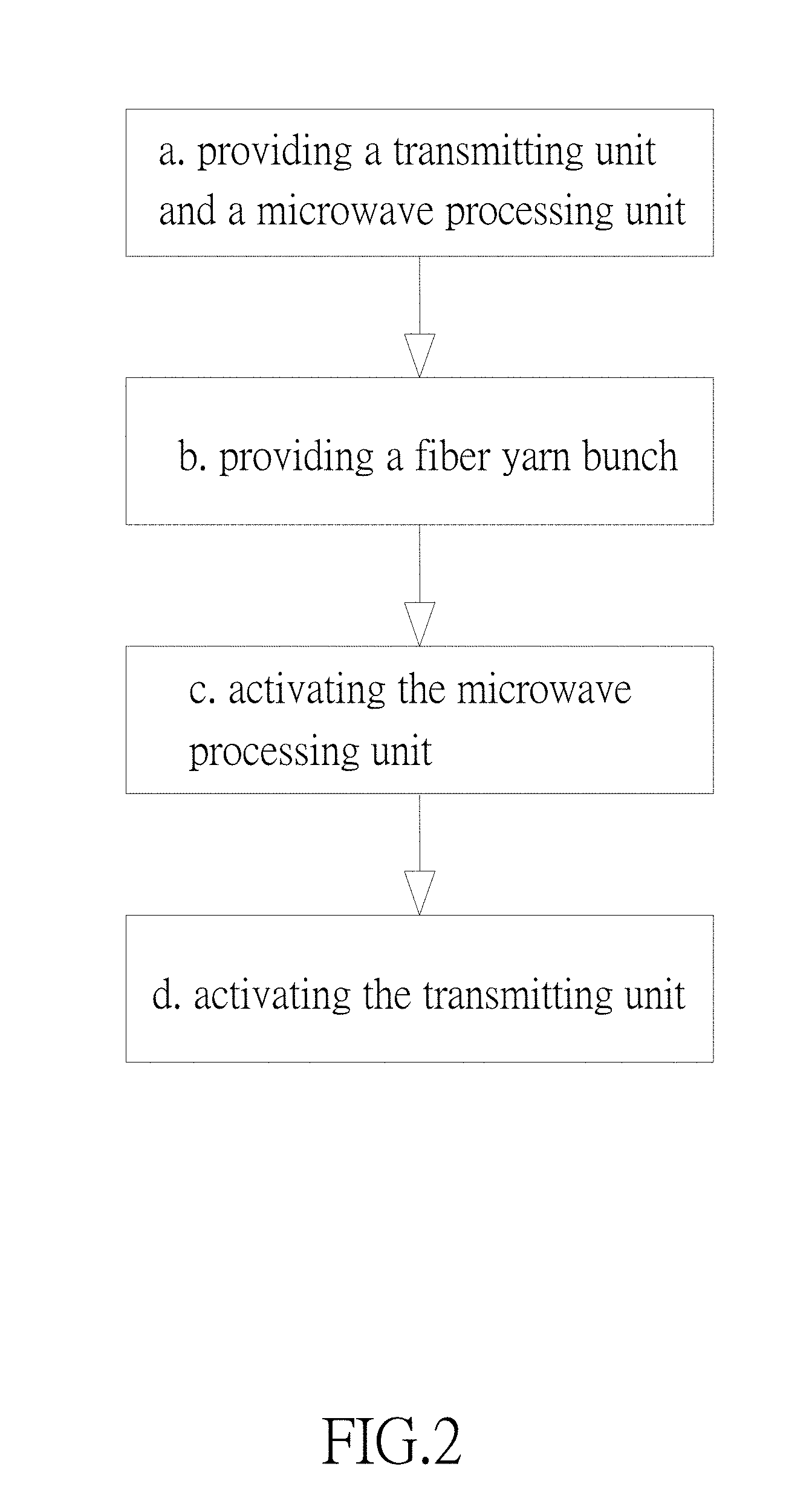
[0029] FIG. 2 is basic flow chart showing an oxidation fiber manufacturing method of the present disclosure.
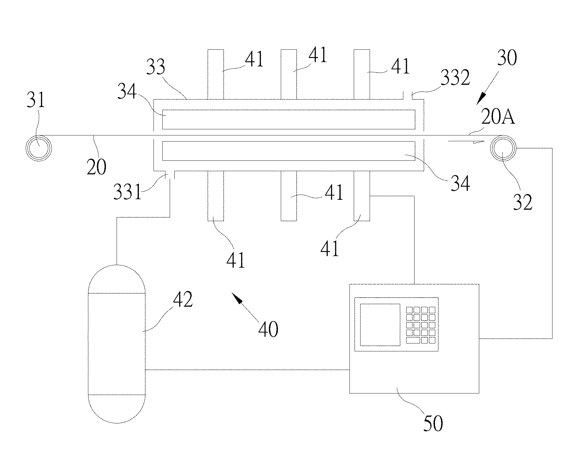
[0030] FIG. 3 is a schematic diagram showing structures of a transmitting unit and a microwave processing unit associated with the oxidation fiber manufacturing method of the present disclosure.
[0031] FIG. 4 is an oxidization degree curve diagram of oxidation fibers associated with fiber yarn bunches on which the 12 kW/m.sup.2, 16 kW/m.sup.2, 20 kW/m.sup.2 , and 24 kW/m.sup.2 microwave focusing processes of and the conventional heating process are respectively performed.
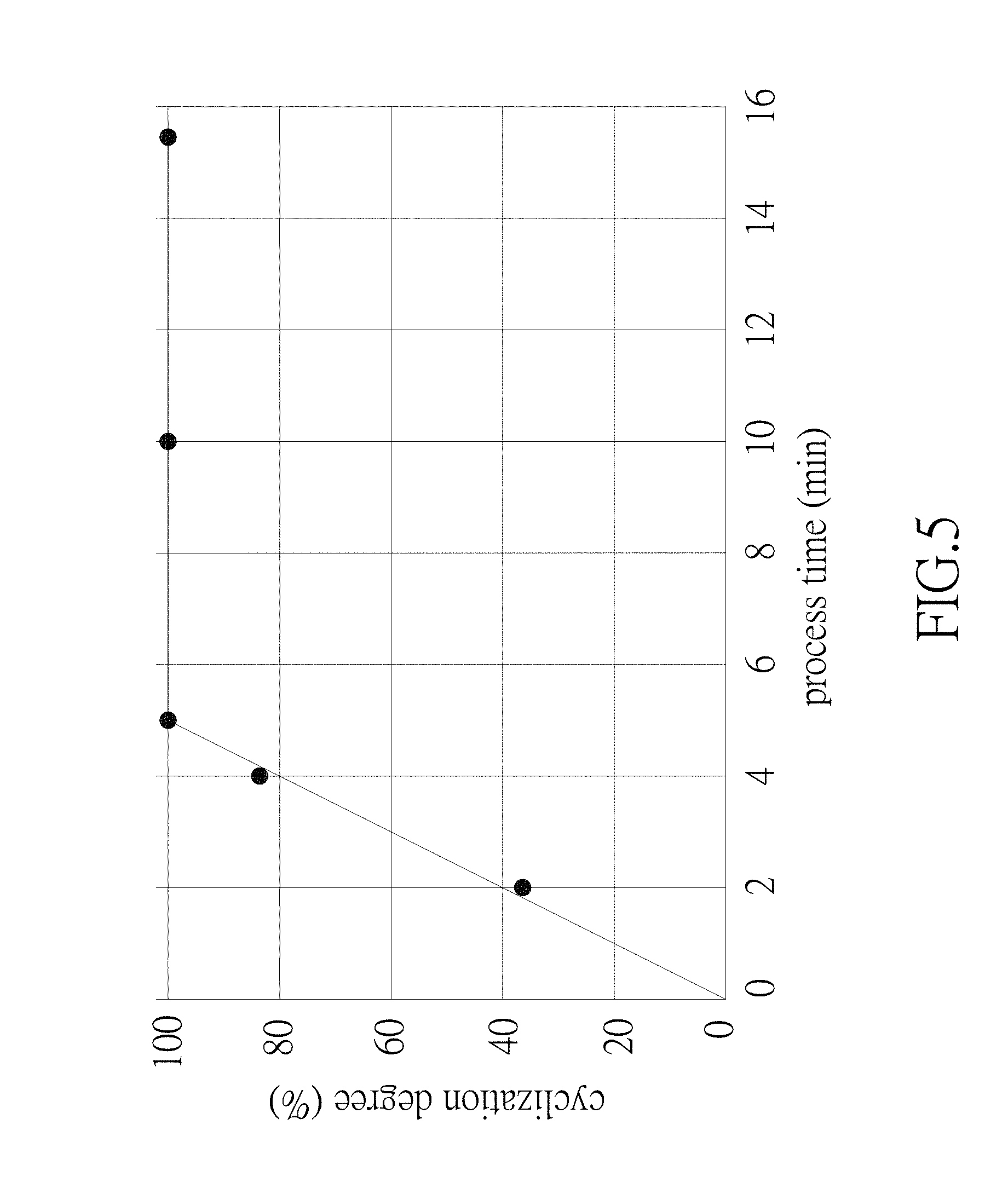
[0032] FIG. 5 is a cyclization degree curve diagram of oxidation fibers associated with fiber yarn bunches on which the 24 kW/m.sup.2 microwave focusing processes are respectively performed for 2 minutes, 4 minutes, 5 minutes, 10 minutes and 15 minutes.
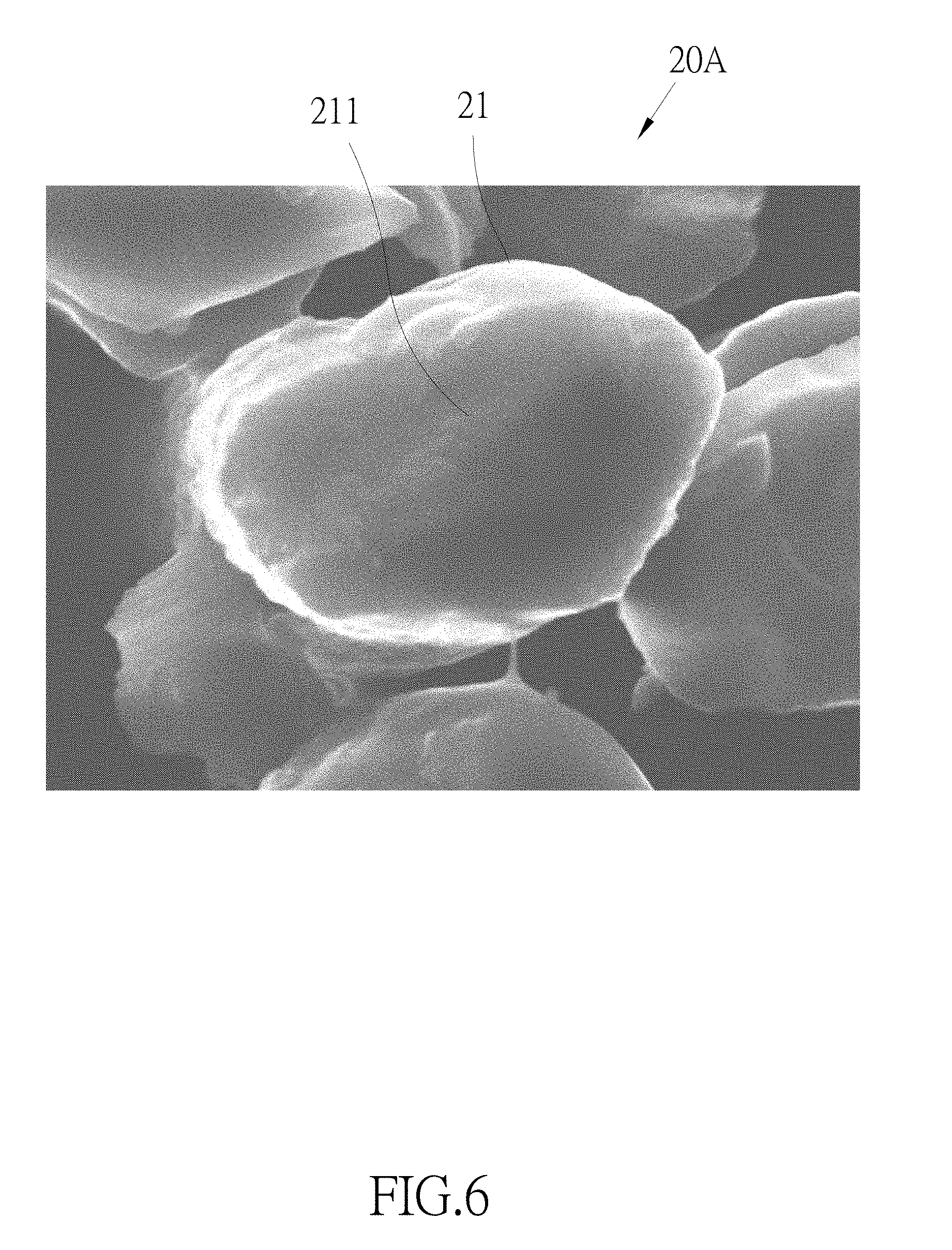
[0033] FIG. 6 is a substantial cross section image of the oxidation fiber of the fiber yarn bunch on which the 24 kW/m.sup.2 microwave focusing process is performed for 5 minutes.
[0034] FIG. 7 is a substantial cross section image of the oxidation fiber of the fiber yarn bunch on which the 24 kW/m.sup.2 microwave focusing process is performed for 10 minutes.
[0035] FIG. 8 is a substantial cross section image of the oxidation fiber of the fiber yarn bunch on which the 24 kW/m.sup.2 microwave focusing process is performed for 15 minutes.
[0036] FIG. 9 is a flow chart of another one oxidation fiber manufacturing method of the present disclosure.
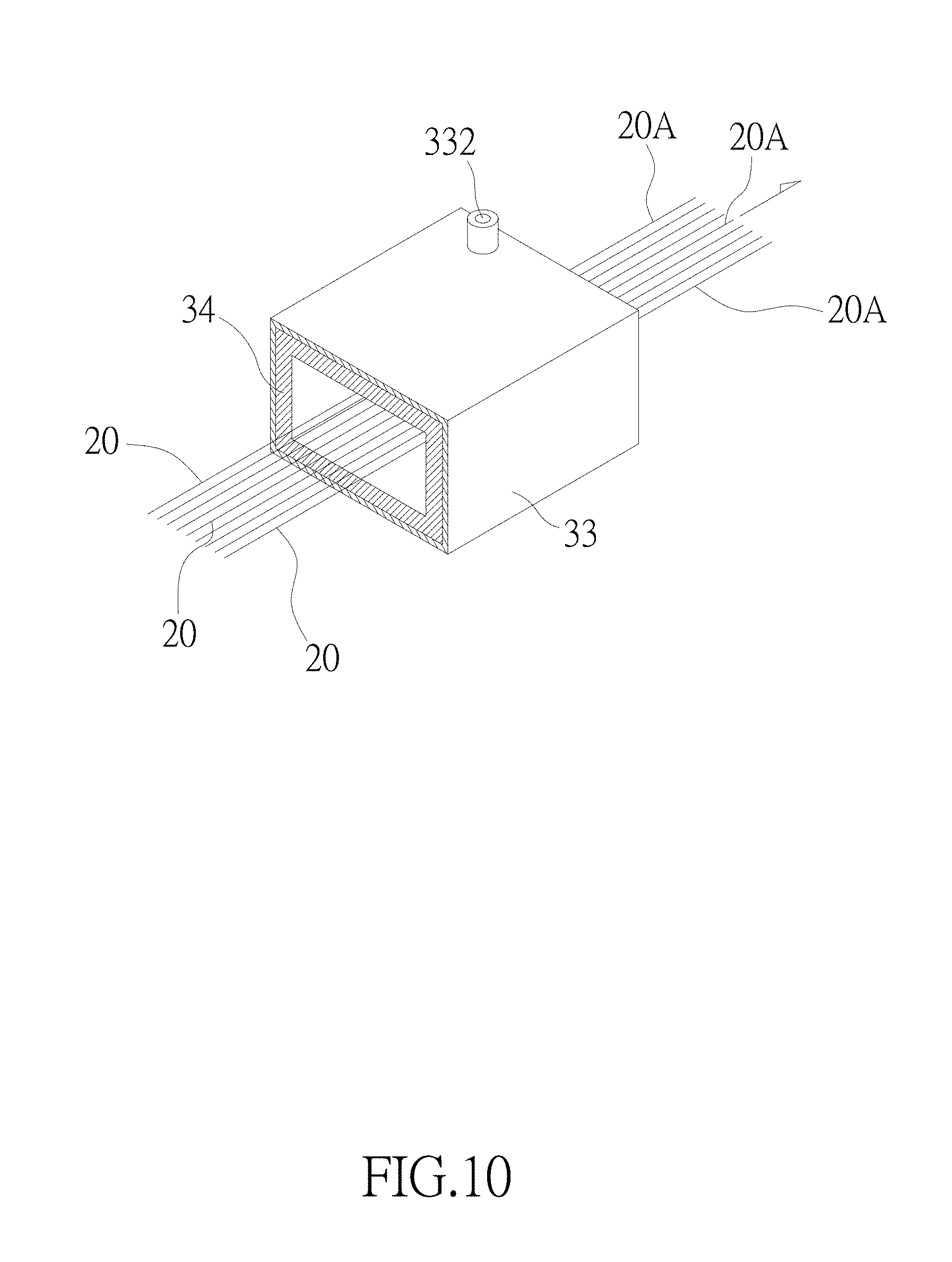
[0037] FIG. 10 is a schematic diagram showing a structure of an oven body associated with the oxidation fiber manufacturing method of the present disclosure.
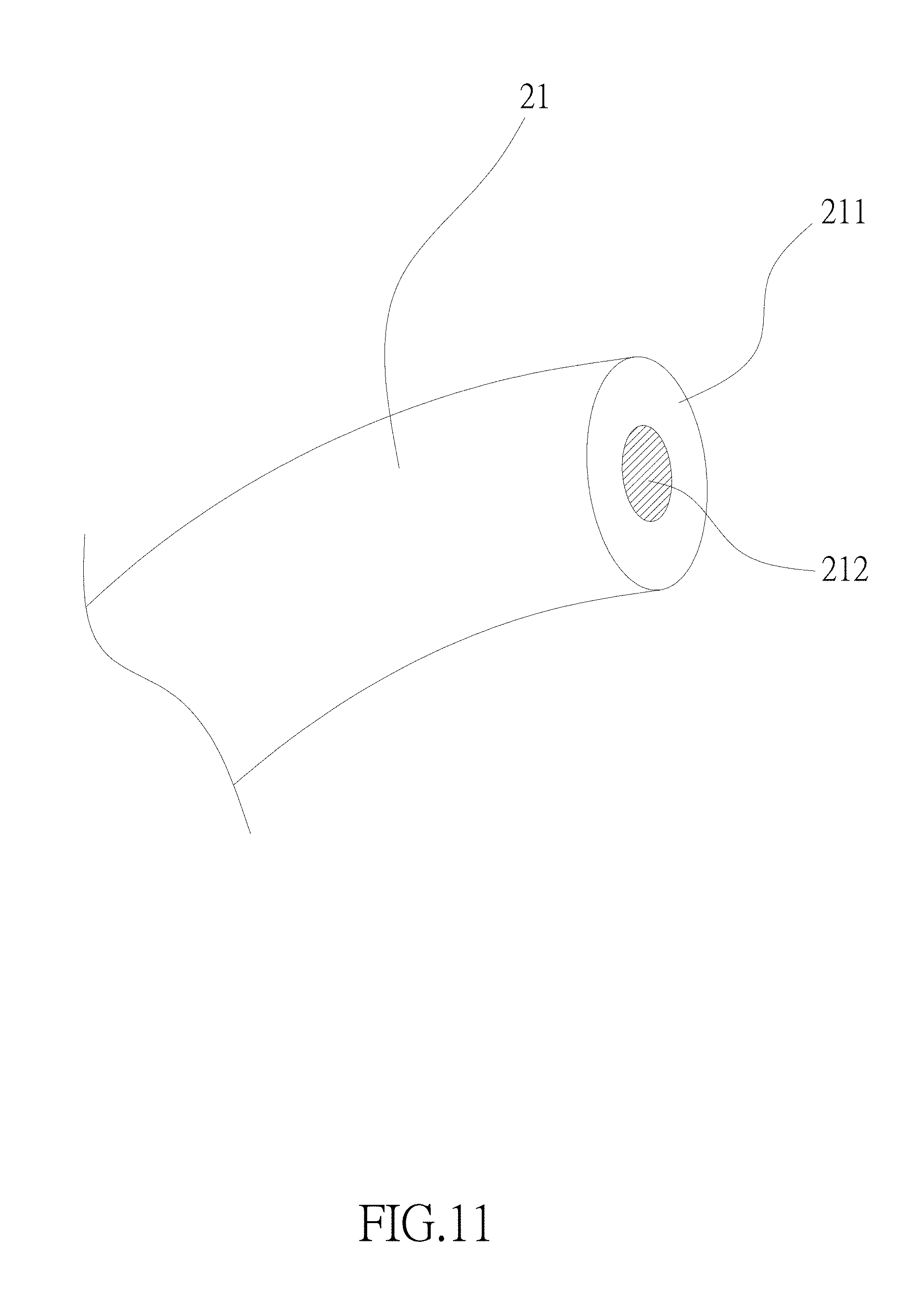
[0038] FIG. 11 is a schematic diagram showing a structure of an oxidation fiber of the present disclosure.
DESCRIPTION OF THE EXEMPLARY EMBODIMENTS
[0039] The present disclosure mainly provides an oxidation fiber manufacturing method which can shorten the oxidization time of the oxidation fiber, efficiently eliminate the shell-core structure of the oxidation fiber, and even make the oxidation fiber have no obvious shell-core structure. As shown in FIG. 2 and FIG. 3, the oxidation fiber manufacturing method basically comprises the following steps.
[0040] Step A: providing a transmitting unit 30 and a microwave processing unit 40. When the present disclosure is implemented, the transmitting unit 30 is installed with a feeding unit 31 for providing the fiber yarn bunch 20, a winder unit 32 for continuously pulling and transmitting the fiber yarn bunch 20, and an oven body 33 which the fiber yarn bunch 20 passes, wherein the fiber yarn bunch 20 is formed by merely one fiber (not shown in the drawings), or alternatively, the fiber yarn bunch 20 is formed by binding a plurality of fibers. The microwave processing unit 40 is installed with a magnetron 41 at the oven body 33 for generating the microwave, and is further installed with an gas supplying unit 42 for injecting a gas atmosphere into the oven body 33. The gas supplying unit 42 is coupled to a gas inlet 331 of the oven body 33, and the gas with the oxygen is injected into the oven body 33 via the gas inlet 331, and exhausted from the oven body 33 via a gas outlet 332 of the oven body 33. The transmitting unit 30 is further installed with a thermos unit 34 in the interior of the oven body 33. Preferably, the microwave processing unit 40 is installed with the plurality of the magnetrons 41 at the oven body 33. The magnetrons 41 are disposed at the top and bottom sides of the oven body 33, and the magnetrons 41 disposed on the top and bottom sides of the oven body 33 are arranged corresponding to each other or in an offset manner, or alternatively, the magnetrons 41 are disposed at single one side of the oven body 33 (such as the top or bottom side). As shown in FIG. 3, the magnetrons 41 are disposed at the top and bottom sides of the oven body 33, and the magnetrons 41 disposed on the top and bottom sides of the oven body 33 are arranged corresponding to each other. Optimally, the magnetrons 41 disposed on the top and bottom sides of the oven body 33 are arranged corresponding to each other as shown in FIG. 3, and thus by simultaneously and uniformly irradiating the microwave on the upper and lower portions of the fiber yarn bunch 20 which passes the oven body 33, the length of the oven body 33 can be correspondingly reduced, and the process time can be shortened to increase the production speed.
[0041] Step B: providing the fiber yarn bunch 20, disposing the fiber yarn bunch 20 in the transmitting unit 30, and making the transmitting unit 30 drive the fiber yarn bunch 20 to pass the microwave processing unit 40. For example, the winded fiber yarn bunch 20 can be disposed at the transmitting unit 30 by the manner that the winded fiber yarn bunch 20 can be continuously driven by the transmitting unit 30 to pass the operation region of the microwave processing unit 40. In the embodiment, the winded fiber yarn bunch 20 is disposed at the feeding unit 31, and the tail end of the fiber yarn bunch 20 is guided to pass the oven body 33 and then fixed on the winder unit 32, wherein the fiber yarn bunch 20 can be one of a polyacrylonitrile (PAN) fiber, a pitch fiber and other one organic fiber.
[0042] Step C: activating the microwave processing unit 40, and using the microwave processing unit 40 to generate a microwaving condition. The microwaving condition comprises: a microwave frequency being 300 MHz through 300,000 MHz; a microwave power being 1 kW/m.sup.2 through 1000 kW/m.sup.2 ; an operation temperature being 100.degree. C. through 600.degree. C.; and a gas atmosphere being at least one of oxygen, air and ozone. The gas atmosphere is the above gas with oxygen. In the embodiment, the gas supplying unit 42 is used to inject the gas with oxygen into the interior of the oven body 33.
[0043] Step D: activating the transmitting unit 30, using the transmitting unit 30 to drive the fiber yarn bunch 20 to be exposed in the microwaving condition for a processing time, so as to transform the fiber yarn bunch 20 to the oxidation fiber yarn bunch 20A. For example, the fiber yarn bunch 20 is driven by the transmitting unit 30 to pass the operation region of the microwave processing unit 40 at the speed which the microwave focusing process is continuously applied for 1 minute through 40 minutes, and that is, the processing time is 1 minute through 40 minutes. In the embodiment, the fiber yarn bunch 20 is driven by the transmitting unit 30 to pass the oven body 33 to form the oxidation fiber yarn bunch 20A at the speed which the microwave focusing process is continuously applied for 1 minute through 40 minutes. In addition, the fiber yarn bunch 20 in the oven body 33 is winded and repeated to pass the oven body 33 to the oxidation fiber yarn bunch 20A at the speed which the microwave focusing process is continuously applied for 1 minute through 40 minutes, so as to form the oxidation fiber yarn bunch 20A. For example, the fiber yarn bunch 20 at the front end of the oven body 33 enters the interior of the oven body 33, and then is transmitted to the back end of the oven body 33. Next, the fiber yam bunch 20 is transmitted from the back end of the oven body 33 to the front end of the oven body 33, and then is transmitted from the front end of the oven body 33 to the back end of the oven body 33 again. The manner is used to repeat and wind the fiber yarn bunch 20 until the requirements is satisfied, and then the fiber yarn bunch 20 is sent out from the back end of the oven body 33 to form the oxidation fiber yarn bunch 20A. The above used repeating and winding manner can sufficiently reduce the required length of the oven body 33.
[0044] Accordingly, by using oxidation fiber manufacturing method, under the operation of the transmitting unit 30, the fiber yarn bunch 20 is driven to pass the operation region of the microwave processing unit 40 at the predetermined speed. During the progress which the fiber yarn bunch 20 passes the operation region of the microwave processing unit 40, the microwave focusing is continuously used to apply the ultra-fast pre-oxidization process on the fiber yarn bunch 20, so as to process the fiber yarn bunch 20 to form the oxidation fiber yam bunch 20A. As shown in FIG. 4, the fiber yarn bunch 20 is formed by merely one fiber, or alternatively, the fiber yarn bunch 20 is formed by binding a plurality of fibers; and the oxidation fiber yarn bunch 20A is formed by merely one oxidation fiber, or alternatively, the oxidation fiber yarn bunch 20A is formed by binding a plurality of oxidation fibers. The oxidation fiber manufacturing method of the present disclosure can be used to pre-oxidize the fiber of the fiber yarn bunch 20 to form the oxidation fiber 21.
[0045] Referring to FIG. 4, the fiber yarn bunches 20 are respectively applied with the non-microwave process and the microwave focusing processes of 12 kW/m.sup.2, 16 kW/m.sup.2, 20 kW/m.sup.2 and 24 kW/m.sup.2 microwave powers, and it can obtain the result that the microwave focusing process of 24 kW/m.sup.2 is applied to the fiber yarn bunch 20 for 10 minutes to make the oxidization degree of the oxidation fiber 21 in the oxidation fiber yarn bunch 20A reach 100%. Corresponding to the fiber yarn bunch 20, the oxidation fiber yarn bunch 20A is formed by merely one oxidation fiber, or alternatively, the oxidation fiber yarn bunch 20A is formed by binding a plurality of oxidation fibers. Similarly, the microwave focusing process of 20 kW/m.sup.2 is applied to the fiber yam bunch 20 for 15 minutes to make the oxidization degree of the oxidation fiber 21 in the oxidation fiber yarn bunch 20A reach 100%. The microwave focusing process of 16 kW/m.sup.2 is applied to the fiber yarn bunch 20 for 25 minutes to make the oxidization degree of the oxidation fiber 21 in the oxidation fiber yarn bunch 20A reach 100%. However, even the microwave focusing process of 12 kW/m.sup.2 is applied to the fiber yarn bunch 20 for 40 minutes, the oxidization degree of the oxidation fiber 21 in the oxidation fiber yarn bunch 20A still cannot reach 100%, but can reach 89%. If the conventional heating process at 270.degree. C. ut the microwave is applied to heat the fiber yarn bunch 20 for 40 minutes, the oxidization degree of the oxidation fiber 21 can merely reaches 70%. Thus, compared the microwaving process provided by the present disclosure to the conventional heating process, the present disclosure can efficiently increase the oxidization degree of the oxidation fiber 21 and shorten the process time. Especially, when the microwave focusing process of 24 kW/m.sup.2 is applied to the fiber yarn bunch 20 for 10 minutes, the oxidization degree of the oxidation fiber 21 in the oxidation fiber yam bunch 20A can reach 100%, and thus the 24 kW/m.sup.2 and 40 minutes are the best process condition of the oxidization stage.
[0046] Referring to FIG. 5, the microwave focusing processes of 24 kW/m.sup.2 are performed on the fiber yarn bunch 20 respectively for 2 minutes, 4 minutes, 5 minutes, 10 minutes and 15 minutes for checking the cyclization degrees of the formed oxidation fibers 21. The cyclization degree of the oxidation fiber 21 reaches 100% after 5 minutes are elapsed. Thus, the required time of 5 minutes that the cyclization degree reaches 100% is less than the required time of 10 minutes that the oxidization degree reaches 100%. Referring to FIG. 6, FIG. 7 and FIG. 8 simultaneously, the cross sections of oxidation fibers 21 associated with the oxidation fiber yarn bunches 20A formed by being processed with the microwave focusing processes of 24 kW/m.sup.2 respectively for 5 minutes, 10 minutes and 15 minutes are photographed by the scanning electron microscope to obtain the substantial cross section images. It is found that the oxidation layer 211 occupies more than 99.0% of the oxidation fiber 21, or the cross section area of the oxidation layer 211 occupies more than 99.0% of the cross section area of the oxidation fiber 21, and no obvious shell-core structure exists.
[0047] Refer to Table 1 and Table 2 simultaneously. Table 1 is a comparison table showing the measured tensile strengths of the fiber yam bunches 20, the oxidation fiber yarn bunches 20A and the carbon fiber yarn bunches formed by the next carbonization, wherein two sets of the fiber yarn bunches 20, the oxidation fiber yarn bunches 20A and the carbon fiber yarn bunches are respectively processed by the conventional electro thermal tube heating process and the microwaving process of the oxidation fiber manufacturing method of the present disclosure. Table 2 is a comparison table showing the measured tensile moduli of the fiber yam bunches 20, the oxidation fiber yarn bunches 20A and the carbon fiber yarn bunches formed by the next carbonization, wherein two sets of the fiber yarn bunches 20, the oxidation fiber yarn bunches 20A and the carbon fiber yarn bunches are respectively processed by the conventional electro thermal tube heating process and the microwaving process of the oxidation fiber manufacturing method of the present disclosure. Regarding the conventional electro thermal tube heating process, the processing condition is the oven body temperature of 270.degree. C. and the p g time of 40 minutes,and the obtained results of the physical properties are called "comparative example 1". Regarding the microwaving process of the oxidation fiber manufacturing method of the present disclosure, the processing condition is the oven body temperature of 220.degree. C., the microwave frequency of 2450 MHz, the microwave power of 24 kW/m.sup.2 and the processing time of 10 minutes, and the obtained results of the physical properties are called "embodiment 1". In both of the comparative example 1 and the embodiment 1, the fiber yarn bunches 20 are made of polyacrylonitrile.
TABLE-US-00001 TABLE 1 the tensile strength the fiber the oxidation fiber the carbon fiber (MPa) yarn bunch yarn bunch yarn bunch comparative 865 221 2824 example 1 embodiment 1 865 164 3675
[0048] In Table 1, the embodiment 1 shows the tensile strength of the final carbon fiber yarn bunch carbonized by the oxidation fiber yarn bunch processed with the microwaving process of the oxidation fiber manufacturing method of the present disclosure is 1.3 times of that in the comparative example 1 (i.e. 3675 divides 2824), and that is the tensile strength has the improvement of 30%. The microwaving process can oxidize polyacrylonitrile more complete, and the tensile strength of the oxidation fiber yarn bunch associated with the microwaving process is slightly less than that of the oxidation fiber yarn bunch associated with the conventional electro thermal tube heating process, which is another one evidence that the microwaving process of the oxidation fiber manufacturing method of the present disclosure can further increase the oxidization degree of the fiber yam bunch.
TABLE-US-00002 TABLE 2 the tensile modulus the fiber the oxidation fiber the carbon fiber (GPa) yarn bunch yarn bunch yarn bunch comparative 8.82 6.03 194.4 example 1 embodiment 1 8.82 6.92 227.1
[0049] In Table 2, embodiment 1 shows the tensile modulus of the final carbon fiber yarn bunch carbonized by the oxidation fiber yarn bunch processed with the microwaving process of the oxidation fiber manufacturing method of the present disclosure is 1.17 times of that in the comparative example 1 (i.e. 227.1 divides 194.4), and that is the tensile modulus has the improvement of 17%.
[0050] Accordingly, compared with the oxidation fiber yarn bunches respectively generated by the fiber yarn bunches on which the conventional heating process and the microwaving process of the present disclosure are performed, the microwaving process of the present disclosure can reduce the required time of the conventional heating process from 40 minutes to 10 minutes, thus the process efficiency is increased with three times, and the process time is reduced. Compared to the conventional heating process, the present disclosure can enhance the 30% tensile strength and the 17% tensile modulus of carbon fiber yarn bunch. Compared to the conventional heating process, the present disclosure can further make the cross section area of the oxidation layer 2111 of the oxidation fiber 21 in the oxidation fiber yarn bunch 20A occupy more than 99.0% of the cross section area of the oxidation fiber 21, such that no obvious shell-core structure exists. The cross section of the oxidation fiber yarn bunch 20A is more uniform, and thus the tensile strength and the tensile modulus of the carbon fiber yarn bunch are increased. The relatively positive and reliable means for enhancing the carbon fiber performance are therefore provided.
[0051] When the oxidation fiber manufacturing method of the present disclosure is implemented, the 24 kW/m.sup.2 microwave focusing process is applied to process the fiber yarn bunch for 5 minutes through 10 minutes, preferably. Certainly, when the oxidation fiber manufacturing method of the present disclosure is implemented, the 24 kW/m.sup.2 microwave focusing process is applied to process the fiber yarn bunch for 5 minutes through 10 minutes. As shown in FIG. 3, the transmitting unit 30 is installed with the feeding unit 31, the winder unit 32 and the oven body 33, wherein the feeding unit 31 is used to provides the fiber yarn bunch 2, the fiber yarn bunch 20 can pass the oven body 33, and the winder unit 32 is used to drag the fiber yarn bunch 20 for continuous transmission and to receive the oxidation fiber yarn bunch 20A. The microwave processing unit 40 is further installed with the magnetron 41 and the gas supplying unit 42, wherein the magnetron 41 is disposed at the oven body 33 for generating the microwave, and the gas supplying unit 42 is used to inject the gas with oxygen into the oven body 33. Accordingly, the oxidation fiber manufacturing method of the present disclosure is adapted to the continuous carbon fiber yarn bunch generation manner that the fiber yarn bunch 20 passes the oven body 33 without the reception and winding of the winder unit 32 and the carbonization is next performed, or alternatively, the oxidation fiber manufacturing method of the present disclosure is adapted to the generation manner that the winded fiber yarn bunch 20 is winded out by the feeding unit 31 and received and winded by the winder unit 32.
[0052] Certainly, the oxidation fiber manufacturing method of the present disclosure can also be adapted to the batch generation manner. The embodiment of the batch generation manner can sequentially execute the following steps, as shown in FIG. 9. The oxidation fiber manufacturing method of the present disclosure can be adapted to pre-oxidize the fiber yarn bunch 20 to form the oxidation fiber yarn bunch 20A. The steps of FIG. 9 are illustrated as follows.
[0053] A yarn bunch providing step S01: preparing the fiber yarn bunch 20. The fiber yarn bunch 20 is formed by merely one fiber, or alternatively, the fiber yarn bunch 20 is formed by binding a plurality of fibers. The fiber yarn bunch 20 is one of a polyacrylonitrile (PAN) fiber, a pitch fiber and other one organic fiber.
[0054] A microwave processing step S02: exposing the fiber yam bunch 20 in the microwaving condition to form the oxidation fiber yarn bunch 20A. The microwaving condition comprises: the microwave frequency being 300 MHz through 300,000 MHz; the microwave power being 1 kW/m.sup.2 through 1000 kW/m.sup.2 ; the operation temperature being 100.degree. C. through 600.degree. C.; the processing time being 1 minute through 40 minutes; and the gas atmosphere being at least one of oxygen, air and ozone.
[0055] Furthermore, the oxidation fiber manufacturing method of the present disclosure is implemented in the embodiment which the microwave processing unit 40 is installed with the gas supplying unit 42 for injecting the gas atmosphere into the oven body 33, wherein the gas atmosphere injected into the oven body 33 by the gas supplying unit 42 is at least one of oxygen, air and ozone.
[0056] Moreover, the oxidation fiber manufacturing method is implemented in the embodiment that the transmitting unit 30 is installed with the feeding unit 31, the winder unit 32 and the oven body 33, and the microwave processing unit 40 is installed with the magnetron 41 and the gas supplying unit 42, wherein the feeding unit 31 is used to provides the fiber yarn bunch 2, the fiber yarn bunch 20 can pass the oven body 33, the winder unit 32 is used to drag the fiber yarn bunch 20 for continuous transmission, the magnetron 41 is disposed at the oven body 33 for generating the microwave, the gas supplying unit 42 is used to inject the gas with oxygen into the oven body 33, and the winder unit 32, the magnetron 41 and the gas supplying unit 42 are electrically connected to a control unit 50. Operations of the winder unit 32, the magnetron 41 and the gas supplying unit 42 are controlled by the control unit 50, and parameters related to the spinning speed of the winder unit 32, the power of the magnetron 41 and flux of the gas supplying unit 42 are determined according to the property of the processed fiber yarn bunch 20 or the product specification.
[0057] the oxidation fiber manufacturing method is implemented in the embodiment that the transmitting unit 30 is installed with the feeding unit 31, the winder unit 32 and the oven body 33, wherein the feeding unit 31 is used to provides the fiber yarn bunch 2, the fiber yarn bunch 20 can pass the oven body 33, the winder unit 32 is used to drag the fiber yarn bunch 20 for continuous transmission, and the transmitting unit 30 is further installed with the thermos unit 34 in the interior of the oven body 33, and as shown in FIG. 10. The thermal storage effect of the thermos unit 34 can be utilized, such that the interior of the oven body 33 can be keep at the predetermined operation temperature to achieve the objective of power saving. In FIG. 10, the feeding unit 31 provides the parallel arranged fiber yarn bunches 20 into the oven body 33.
[0058] When the oxidation fiber manufacturing method of the present disclosure is implemented, the transmitting unit 30 as shown in FIG. 3, the thermos units 34 are respectively disposed at top and bottom sides of the interior of the oven body 33 in respective to a transmission path of the fiber yam bunch 20; or alternatively, as shown in FIG. 10, the thermos unit 34 is disposed in the interior of the oven body 33 for covering the transmission path of the fiber yarn bunch 20, such that the fiber yarn bunch 20 is heated uniformly.
[0059] According to the above possible embodiments associated with the oxidation fiber manufacturing of the present disclosure, the thermos unit 34 can be selected from at least one of a metal oxide, a carbide and a high microwave sensitive material.
[0060] When the oxidation fiber manufacturing of the present disclosure is implemented, as shown in FIG. 3, the magnetrons 41 are respectively disposed at top and bottom sides of the transmission path of the fiber yarn bunch 20; or alternatively, the magnetrons 41 are disposed for covering the transmission path of the fiber yarn bunch 20, such that the microwave focusing process is uniformly performed on the fiber yarn bunch 20.
[0061] Referring to FIG. 4 again, after the microwave focusing process of the 12 kW/m.sup.2 microwave power at 220.degree. C. is applied to the fiber yarn bunch 20 for 40 minutes, the oxidation degree of the oxidation fiber 21 reaches 89%. However, after the conventional heating process at 270.degree. C. is applied to the fiber yarn bunch 20 for 40 minutes without the microwaving process, the oxidation degree of the oxidation fiber 21 merely reaches 70%. Therefore, compared to the conventional heating process, the oxidation fiber manufacturing of the present disclosure can obtain the higher oxidation degree at the lower temperature, thus preventing the thermal waste.
[0062] Refer to Table 3, and Table 3 is a comparison table showing the measured tensile strengths of the fiber yarn bunches 20, the oxidation fiber yarn bunches 20A and the carbon fiber yarn bunches formed by the next carbonization, wherein several sets of the fiber yarn bunches 20, the oxidation fiber yarn bunches 20A and the carbon fiber yarn bunches are respectively processed by the conventional electro thermal tube heating process and the microwaving processes of the oxidation fiber manufacturing method of the present disclosure. Regarding the conventional electro thermal tube heating process, the processing condition is the oven body temperature of 270.degree. C. and the processing time of 40 minutes, and the obtained results of the physical roperties are called "comparative example 1". Regarding the microwaving processes of the present disclosure, the processing conditions are the oven body temperature of 220.degree. C., the microwave frequency of 2450 MHz and the processing time of 10 minutes, and the obtained results of the physical properties associated with 24 kW/m.sup.2, 22 kW/m.sup.2, 16 kW/m.sup.2 and 15 kW/m.sup.2 microwave powers are called "embodiment 1", "embodiment 2", "embodiment 3", "embodiment 4" and "embodiment 5". In all of comparative example 1 and embodiments 1 through 5, the fiber yarn bunches 20 are made of polyacrylonitrile. In addition, the cross sections of the oxidation fibers 21 of the oxidation fiber yarn bunches 20A associated with all of the comparative example 1 and the embodiments 1 through 5 are photographed by the scanning electron microscope to obtain the substantial cross section images, and the calculated values that the cross section areas of the oxidation layers 211 respectively divide the cross section areas of the oxidation fibers 21, i.e. the ratios which the oxidation layers 211 occupy the oxidation fibers 21, are also listed in Table 3.
TABLE-US-00003 TABLE 3 the tensile strength of the the the fiber microwave tensile yarn bunch power X* strength number (MPa) (kW/m.sup.2) (MPa) ratio R* comparative 865 0 2824 1 .sup. 40% example 1 embodiment 1 865 24 3675 1.30 99.0% embodiment 2 865 22 3580 1.27 91.3% embodiment 3 865 20 3486 1.23 82.7% embodiment 4 865 16 3298 1.17 61.5% embodiment 5 865 15 3204 1.13 51.2% X*: the tensile strength of the carbon fiber yarn bunch R*: the value that the cross section area of the oxidation layer divides cross section area of the oxidation fiber
[0063] In Table 3, embodiment 5 shows the tensile strength of the final carbon fiber yarn bunch carbonized by the oxidation fiber yarn bunch processed with the microwaving process of the present disclosure is 1.13 times of that in the comparative example 1, and that is the tensile strength has the improvement of 13%. In embodiment 5, the value that the cross section area of the oxidation layer 211 divides the cross section area of the oxidation fiber 21 is 51.2%, i.e. the oxidation layer 211 occupies the 51.2% oxidation fiber 21. Embodiment 4 shows the tensile strength of the final carbon fiber yam bunch carbonized by the oxidation fiber yarn bunch processed with the microwaving process of the present disclosure is 1.17 times of that in the comparative example 1, and that is the tensile strength has the improvement of 17%. In embodiment 4, the value that the cross section area of the oxidation layer 211 divides the cross section area of the oxidation fiber 21 is 61.5%, i.e. the oxidation layer 211 occupies the 61.5% oxidation fiber 21. Embodiment 3 shows the tensile strength of the final carbon fiber yarn bunch carbonized by the oxidation fiber yarn bunch processed with the microwaving process of the present disclosure is 1.23 times of that in the comparative example 1, and that is the tensile strength has the improvement of 23%. In embodiment 3, the value that the cross section area of the oxidation layer 211 divides the cross section area of the oxidation fiber 21 is 82.7%, i.e. the oxidation layer 211 occupies the 82.7% oxidation fiber 21. Embodiment 2 shows the tensile strength of the final carbon fiber yarn bunch carbonized by the oxidation fiber yarn bunch processed with the microwaving process of the present disclosure is 1.27 times of that in the comparative example 1, and that is the tensile strength has the improvement of 27%. In embodiment 2, the value that the cross section area of the oxidation layer 211 divides the cross section area of the oxidation fiber 21 is 91.3%, i.e. the oxidation layer 211 occupies the 91.3% oxidation fiber 21. Embodiment 1 shows the tensile strength of the final carbon fiber yam bunch carbonized by the oxidation fiber yarn bunch processed with the microwaving process of the present disclosure is 1.3 times of that in the comparative example 1, and that is the tensile strength has the improvement of 30%. In embodiment 1, the value that the cross section area of the oxidation layer 211 divides the cross section area of the oxidation fiber 21 is 99.0%, i.e. the oxidation layer 211 occupies the 99.0% oxidation fiber 21.
[0064] Thus, the present disclosure further discloses the oxidation fiber 21, and the oxidation fiber 21 comprises an oxidation layer 211 and a core portion 212, wherein the oxidation layer 211 covers the outer side of the core portion 212, and the oxidation layer 211 occupy the more than 50% oxidation fiber 21, or the cross section area of the oxidation layer 211 occupy the more than 50% cross section area of the oxidation fiber 21. As shown in FIG. 11, the oxidation layer 211 occupy the more than 80% oxidation fiber 21, or the cross section area of the oxidation layer 211 occupy the more than 80% cross section area of the oxidation fiber 21.
[0065] Certainly, the oxidation fiber 21 of the present disclosure can be formed by using one of the above oxidation fiber manufacturing methods to process the fiber yarn bunch 20. Since the oxidation fiber 21 of the present disclosure is formed under the microwaving condition, the oxidation layer 211 is a microwaved oxidation layer, and the oxidation layer 211 of the oxidation fiber 21 in the oxidation fiber yarn bunch 20A occupies the at least 50% oxidation fiber 21.
[0066] When the present disclosure is implemented, the fiber yarn bunch 20 can be one of polyacrylonitrile, pitch and other organic fibers. Certainly, after the microwave focusing process of 24 kW/m.sup.2 microwave power is applied on the fiber yarn bunch 20 for 10 minutes to obtain the oxidation fiber, the oxidation layer 211 occupy the 99.0% oxidation fiber 21, or the cross section area of the oxidation layer 211 occupy the 99.0% cross section area of the oxidation fiber 21.
[0067] Compared to the prior art, the oxidization fiber manufacturing method disclosed by the present disclosure mainly uses the microwave processing unit to focus the microwave to apply the ultra-fast pre-oxidization process on the fiber yarn bunch, so as to process the fiber yam bunch to form the oxidation fiber. Thus, not only the oxidization time of the oxidation fiber is reduced, but also the oxidation layer in the oxidation fiber processed by the microwaving and oxidizing process occupies more than 50% of the cross section area of the oxidation fiber to efficiently reduce shell-core structure of the oxidation fiber. Even, no obvious shell-core structure exists in the oxidation fiber. Accordingly, relatively positive and reliable means for increasing the performance of carbon fiber are provided.
[0068] The above-mentioned descriptions represent merely the exemplary embodiment of the present disclosure, without any intention to limit the scope of the present disclosure thereto. Various equivalent changes, alternations or modifications based on the claims of present disclosure are all consequently viewed as being embraced by the scope of the present disclosure.
* * * * *
D00000
D00001
D00002
D00003
D00004
D00005
D00006
D00007
D00008
D00009
D00010
D00011
XML
uspto.report is an independent third-party trademark research tool that is not affiliated, endorsed, or sponsored by the United States Patent and Trademark Office (USPTO) or any other governmental organization. The information provided by uspto.report is based on publicly available data at the time of writing and is intended for informational purposes only.
While we strive to provide accurate and up-to-date information, we do not guarantee the accuracy, completeness, reliability, or suitability of the information displayed on this site. The use of this site is at your own risk. Any reliance you place on such information is therefore strictly at your own risk.
All official trademark data, including owner information, should be verified by visiting the official USPTO website at www.uspto.gov. This site is not intended to replace professional legal advice and should not be used as a substitute for consulting with a legal professional who is knowledgeable about trademark law.