Sheet Feeding Apparatus, Image Forming Apparatus, And Image Forming System
NAKAMURA; Hajime
U.S. patent application number 16/240280 was filed with the patent office on 2019-08-01 for sheet feeding apparatus, image forming apparatus, and image forming system. The applicant listed for this patent is Konica Minolta, Inc.. Invention is credited to Hajime NAKAMURA.
| Application Number | 20190233226 16/240280 |
| Document ID | / |
| Family ID | 67391876 |
| Filed Date | 2019-08-01 |


| United States Patent Application | 20190233226 |
| Kind Code | A1 |
| NAKAMURA; Hajime | August 1, 2019 |
SHEET FEEDING APPARATUS, IMAGE FORMING APPARATUS, AND IMAGE FORMING SYSTEM
Abstract
A sheet feeding apparatus includes: a front edge air part that blows front edge air, along a conveying direction of a sheet stacked, to a front edge side of the sheet; side edge air parts that are provided to face each other along an orthogonal direction to the conveying direction of the sheet and blow side edge air, along the orthogonal direction, to respective side edge sides of the sheet; a suction part that suctions, by a negative pressure, the sheet to which the front edge air and the side edge air are blown; and a conveyer that suctions and conveys the sheet suctioned by the suction part, wherein the front edge air and the side edge air are blown to the sheet to float the sheet in a posture in which a portion protruding from the conveyer of the sheet is lower than a conveying surface of the conveyer.
| Inventors: | NAKAMURA; Hajime; (Tokyo, JP) | ||||||||||
| Applicant: |
|
||||||||||
|---|---|---|---|---|---|---|---|---|---|---|---|
| Family ID: | 67391876 | ||||||||||
| Appl. No.: | 16/240280 | ||||||||||
| Filed: | January 4, 2019 |
| Current U.S. Class: | 1/1 |
| Current CPC Class: | B65H 1/16 20130101; B65H 2511/11 20130101; B65H 3/08 20130101; B65H 1/20 20130101; B65H 3/48 20130101; B65H 2220/02 20130101; B65H 3/128 20130101; B65H 2405/15 20130101; B65H 2515/342 20130101; B65H 7/04 20130101; B65H 2511/11 20130101; B65H 2515/342 20130101; B65H 2220/01 20130101 |
| International Class: | B65H 1/20 20060101 B65H001/20; B65H 1/16 20060101 B65H001/16; B65H 3/08 20060101 B65H003/08; B65H 3/48 20060101 B65H003/48 |
Foreign Application Data
| Date | Code | Application Number |
|---|---|---|
| Feb 1, 2018 | JP | 2018-016430 |
Claims
1. A sheet feeding apparatus comprising: a front edge air part that blows front edge air, along a conveying direction of a sheet stacked, to a front edge side of the sheet; side edge air parts that are provided to face each other along an orthogonal direction to the conveying direction of the sheet and blow side edge air, along the orthogonal direction, to respective side edge sides of the sheet; a suction part that suctions, by a negative pressure, the sheet to which the front edge air and the side edge air are blown; and a conveyer that suctions and conveys the sheet suctioned by the suction part, wherein the front edge air and the side edge air are blown to the sheet to float the sheet in a posture in which a portion protruding from the conveyer of the sheet is lower than a conveying surface of the conveyer.
2. The sheet feeding apparatus according to claim 1, wherein two or more sets of the side edge air parts are provided along the conveying direction, and in a case where a length of the sheet is equal to or greater than a preset threshold, until the sheet is suctioned by the conveyer, at least one of strength, a blowing position, or a blowing direction of the side edge air is set to float the sheet in a posture in which the sheet is lower in lifting of the sheet by upstream side edge air of the side edge air blown from an upstream side along the conveying direction than in lifting of the sheet by downstream side edge air of the side edge air blown from a downstream side along the conveying direction.
3. The sheet feeding apparatus according to claim 1, wherein strength of upstream side edge air of the side edge air blown from an upstream side along the conveying direction is set weaker than strength of downstream side edge air of the side edge air blown from a downstream side along the conveying direction.
4. The sheet feeding apparatus according to claim 1, wherein a position of a side edge air opening of upstream side edge air of the side edge air blown from an upstream side along the conveying direction is provided at a lower position in a stacking direction of the sheet than a position of a side edge air opening of downstream side edge air of the side edge air blown from a downstream side along the conveying direction.
5. The sheet feeding apparatus according to claim 1, wherein a blowing direction of upstream side edge air of the side edge air blown from the upstream side along the conveying direction is set more downward in a stacking direction of the sheet than a blowing direction of downstream side edge air of the side edge air blown from a downstream side along the conveying direction.
6. The sheet feeding apparatus according to claim 1, further comprising a side edge detection sensor that detects a posture of a side edge of the sheet, wherein the side edge air part changes an amount of blowing of the side edge air depending on a floating height of the sheet detected by the side edge detection sensor.
7. The sheet feeding apparatus according to claim 6, further comprising a side edge guide member that includes the side edge air part and guides the posture of the side edge of the sheet, wherein the side edge air part stops blowing of the side edge air in a case where it is detected by the side edge detection sensor that the sheet has come out of the side edge guide member.
8. An image forming apparatus comprising: a front edge air part that blows front edge air, along a conveying direction of a sheet stacked, to a front edge side of the sheet; side edge air parts that are provided to face each other along an orthogonal direction to the conveying direction of the sheet and blow side edge air, along the orthogonal direction, to respective side edge sides of the sheet; a suction part that suctions, by a negative pressure, the sheet to which the front edge air and the side edge air are blown; and a conveyer that suctions and conveys the sheet suctioned by the suction part, wherein the front edge air and the side edge air are blown to the sheet to float the sheet in a posture in which a portion protruding from the conveyer of the sheet is lower than a conveying surface of the conveyer.
9. An image forming system comprising: a front edge air part that blows front edge air, along a conveying direction of a sheet stacked, to a front edge side of the sheet; side edge air parts that are provided to face each other along an orthogonal direction to the conveying direction of the sheet and blow side edge air, along the orthogonal direction, to respective side edge sides of the sheet; a suction part that suctions, by a negative pressure, the sheet to which the front edge air and the side edge air are blown; and a conveyer that suctions and conveys the sheet suctioned by the suction part, wherein the front edge air and the side edge air are blown to the sheet to float the sheet in a posture in which a portion protruding from the conveyer of the sheet is lower than a conveying surface of the conveyer.
Description
[0001] The entire disclosure of Japanese patent Application No. 2018-016430, filed on Feb. 1, 2018, is incorporated herein by reference in its entirety.
BACKGROUND
Technological Field
[0002] The present disclosure relates to a sheet feeding apparatus, an image forming apparatus, and an image forming system.
Description of the Related Art
[0003] Conventionally, an air suction type sheet feeding apparatus is known as a sheet feeding apparatus for feeding a sheet to an image forming apparatus such as a copying machine or a printer. There is an air suction type sheet feeding apparatus including a conveyer that generates a negative pressure above stacked sheet and suctions air to cause the uppermost sheet to be suctioned. Such an air suction type sheet feeding apparatus blows air from the front edge or the side edge of the sheet to float the sheet to cause the sheet to be suctioned by the conveyer, thereby being able to feed sheets of the plural stacked sheets one by one.
[0004] Thus, if the sheet is long, since the entire sheet does not float only by blowing air from the front edge of the sheet, air blown from the side edge is increased depending on the length of the sheet. By floating the sheet with the air from the side edge, the floated sheet can be brought into a state not in contact with the sheet still stacked. If contact between sheets due to suction can be avoided, it is possible to suppress double feed of the sheets, conveying resistance, and paper dust generation due to rubbing between the sheets. However, although the floated sheet can be suctioned and stopped at a place where there is the conveyer, the sheet excessively rises at a place where there is no conveyer, and a floating posture of the sheet becomes unstable. As the sheet length increases, it becomes disadvantageous to stabilize the floating posture of the sheet. An apparatus has therefore been devised in which a regulating member is provided above a stacking surface of a sheet to regulate floating of the sheet at a portion where there is no conveyer (for example, see JP 2013-043745 A).
[0005] However, even with the conventional technique as described in JP 2013-043745 A, if a portion of the sheet protrudes from the regulating member, it becomes impossible to suppress the protruding portion of the sheet with the regulating member, and the floating posture of the sheet becomes unstable. As a result, there is a possibility that the sheet separates from the conveyer and the sheet twists on the way. Thus, to perform stable floating operation by the above conventional technique, it is necessary to increase the size of the regulating member as the length of the sheet becomes longer, so that it is not possible to avoid an increase in size and cost of the apparatus. In addition, in the above conventional technique, since the regulating member directly contacts the sheet, there is a possibility of generating a scratch mark or paper dust on the sheet surface, and the regulating member that contacts the sheet is undesirable.
SUMMARY
[0006] The present disclosure has been made in view of such a situation, and an object of the present invention is to enable stable floating operation in a non-contact manner while avoiding an increase in size and cost of the apparatus.
[0007] To achieve the abovementioned object, according to an aspect of the present invention, a sheet feeding apparatus reflecting one aspect of the present invention comprises: a front edge air pan that blows front edge air, along a conveying direction of a sheet stacked, to a front edge side of the sheet; side edge air parts that are provided to face each other along an orthogonal direction to the conveying direction of the sheet and blow side edge air, along the orthogonal direction, to respective side edge sides of the sheet; a suction part that suctions, by a negative pressure, the sheet to which the front edge air and the side edge air are blown; and a conveyer that suctions and conveys the sheet suctioned by the suction part, wherein the front edge air and the side edge air are blown to the sheet to float the sheet in a posture in which a portion protruding from the conveyer of the sheet is lower than a conveying surface of the conveyer.
BRIEF DESCRIPTION OF THE DRAWINGS
[0008] The advantages and features provided by one or more embodiments of the invention will become more fully understood from the detailed description given hereinbelow and the appended drawings which are given by way of illustration only, and thus are not intended as a definition of the limits of the present invention:
[0009] FIG. 1 is a diagram illustrating an overall configuration example of an image forming system in an embodiment of the present disclosure;
[0010] FIG. 2 is a diagram illustrating an example of a main part configuration of a sheet feeding apparatus in the embodiment of the present disclosure;
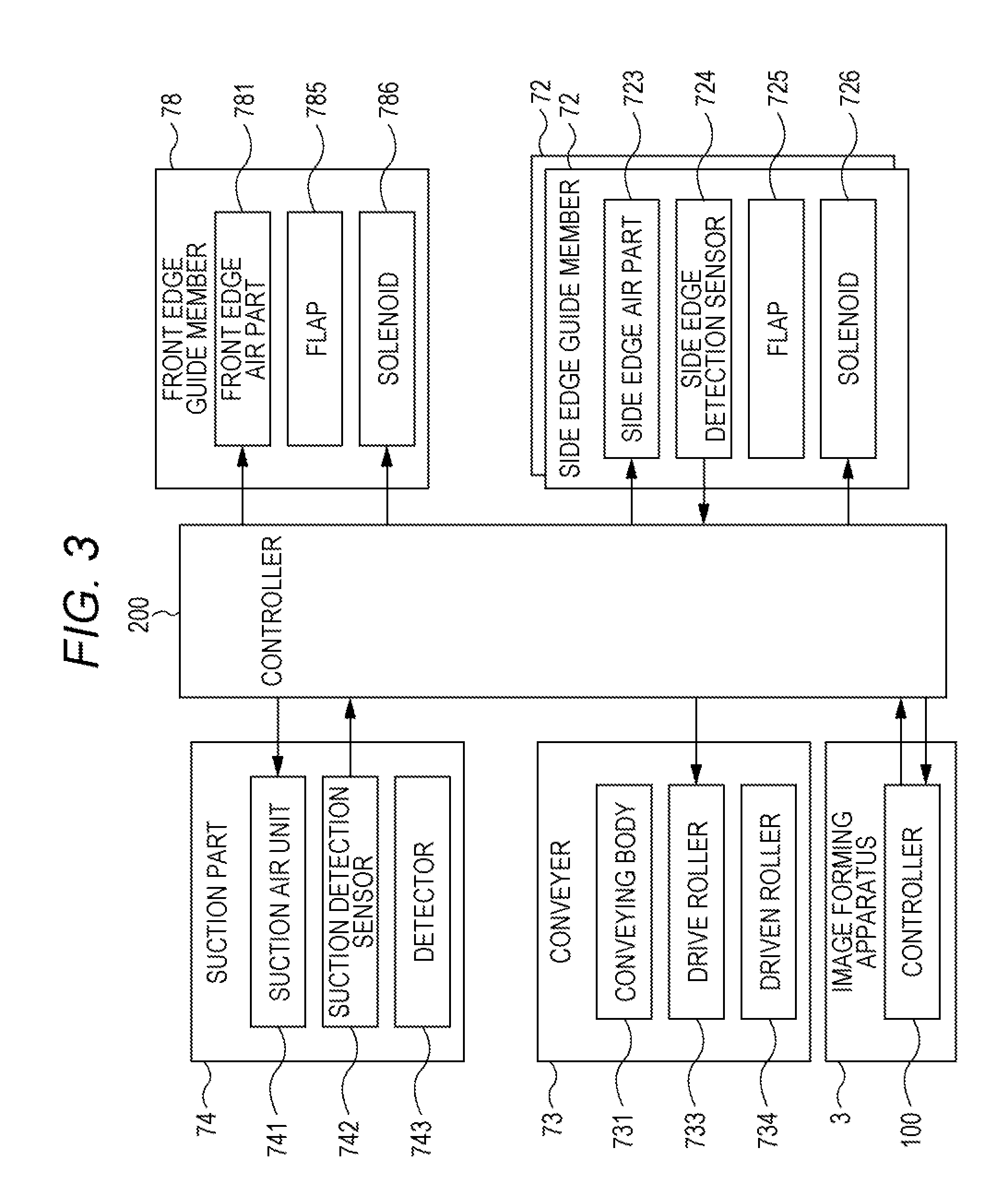
[0011] FIG. 3 is a diagram illustrating a main part of a control system of the sheet feeding apparatus in the embodiment of the present disclosure;
[0012] FIG. 4 is a diagram illustrating an example of a floating posture of a sheet when front edge air is blown to the sheet from a front edge air part in the embodiment of the present disclosure;
[0013] FIG. 5 is a diagram illustrating an example of the floating posture of the sheet when side edge air is blown to the sheet from a side edge air pan in the embodiment of the present disclosure;
[0014] FIG. 6 is a diagram illustrating an example of the floating posture of the sheet when the sheet separates from a conveyer in the embodiment of the present disclosure;
[0015] FIG. 7 is a diagram illustrating an example of a state in which the floating posture of the sheet in the embodiment of the present disclosure is between a conveying surface of the conveyer and a stacking surface of the sheet;
[0016] FIG. 8 is a diagram illustrating an example of a state in which the floating posture of the sheet in the embodiment of the present disclosure has come out of side edge guide members;
[0017] FIGS. 9A to 9C are diagrams illustrating an example of blowing order of air to the sheet in the embodiment of the present disclosure;
[0018] FIG. 10 is a diagram illustrating an example of a position of a side edge air opening of the side edge air in the embodiment of the present disclosure;
[0019] FIG. 11 is a diagram illustrating an example of a variable configuration of a blowing direction of the side edge air of the side edge air part in the embodiment of the present disclosure;
[0020] FIG. 12 is a diagram illustrating an example of the floating posture of a second sheet in the embodiment of the present disclosure;
[0021] FIGS. 13A and 13B are diagrams illustrating an example of a floating detection function in the embodiment of the present disclosure; and
[0022] FIG. 14 is a flowchart illustrating a control example in the embodiment of the present disclosure.
DETAILED DESCRIPTION OF EMBODIMENTS
[0023] Hereinafter, one or more embodiments of the present invention will be described with reference to the drawings. However, the scope of the invention is not limited to the disclosed embodiments.
[0024] FIG. 1 is a diagram illustrating an overall configuration example of an image forming system 1 in the embodiment of the present disclosure. As illustrated in FIG. 1, the image forming system 1 has a configuration in which a sheet feeding apparatus 2 of an external type with large capacity is connected to a side of an image forming apparatus 3. The sheet feeding apparatus 2 includes three stages of sheet feeding units 201A, 201B, and 201C, and feeds a sheet P one by one to the image forming apparatus 3. The sheet feeding apparatus 2 includes a controller 200. The controller 200 includes a CPU, ROM, RAM, and a storage unit. The storage unit is implemented by a hard disk drive or a nonvolatile semiconductor memory such as a flash memory, and stores various data. The controller 200 cooperates with a controller 100 of the image forming apparatus 3 to control operation of each unit of the sheet feeding apparatus 2. The controller 200 controls a conveyer 73, a suction part 74, and a conveying path unit 75 on the basis of a control signal from the image forming apparatus 3. Details of the sheet feeding apparatus 2 will be described later.
[0025] The image forming apparatus 3 is an apparatus that forms color image of an intermediate transfer system using an electrophotographic process technology. In the image forming apparatus 3, a vertical tandem system is adopted in which photosensitive drums respectively corresponding to four colors of Y, M, C, K are serially arranged in a traveling direction, that is, in a vertical direction of an intermediate transfer belt, and each color toner image is sequentially transferred to the intermediate transfer belt in a single procedure. That is, the image forming apparatus 3 forms an image by performing primary transfer of each color toner image of yellow (Y), magenta (M), cyan (C), black (K) formed on each photosensitive drum to the intermediate transfer belt, and laying over the toner images of four colors on the intermediate transfer belt, and then performing secondary transfer to the sheet P or a sheet S.
[0026] The image forming apparatus 3 includes an image reading unit 10, an operation display unit 20, an image processing unit 30, an image forming unit 40, a sheet conveying unit 50, a fixing unit 60, and a controller 100. The controller 100 includes a CPU, ROM, RAM, and a storage unit. The CPU reads a program depending on processing details from the ROM and deploys the program on the RAM, and controls operation of each unit of the image forming apparatus 3 by cooperating with the program deployed. The storage unit is implemented by a hard disk drive or a nonvolatile semiconductor memory such as a flash memory, and stores various data. The various data stored in the storage unit are referenced when the CPU controls the operation of the image forming apparatus 3. In addition, the controller 100 cooperates with the controller 200 of the sheet feeding apparatus 2 to control operation of the sheet feeding apparatus 2.
[0027] The image reading unit 10 includes an automatic document sheet feeding device 11, and a document image scanning device 12. The automatic document sheet feeding device 11 is referred to as an Auto Document Feeder (ADF). The automatic document sheet feeding device 11 conveys a document placed on a document tray with a conveying mechanism, and feeds the document to the document image scanning device 12. The automatic document sheet feeding device 11 can continuously read images of a large number of documents placed on the document tray. When continuously reading images of the large number of documents, the automatic document sheet feeding device 11 can read both sides of each document with a sheet reversing mechanism. The document image scanning device 12 optically scans a document conveyed on a contact glass from the automatic document sheet feeding device 11 or a document placed on the contact glass. The document image scanning device 12 reads a document image formed on the document by forming an image of reflected light from the document obtained by optical scanning on a light receiving surface of a CCD sensor. The image reading unit 10 generates input image data of the document image on the basis of a reading result by the document image scanning device 12. The input image data is supplied to the image processing unit 30, and the image processing unit 30 executes preset image processing.
[0028] The operation display unit 20 is implemented by a liquid crystal display (LCD) with a touch panel, for example, and functions as a display unit 21 and an operation unit 22. The display unit 21 displays various operation screens, a state of the image, operating conditions of the functions, and the like, in accordance with a display control signal input from the controller 100. The operation unit 22 includes various operation keys such as a numeric keypad and a start key. The operation unit 22 accepts various types of input operation by a user, thereby generating an operation signal. The operation signal is output to the controller 100.
[0029] The image processing unit 30 includes a circuit for performing digital image processing according to an initial setting or a user setting, on the input image data. For example, under the control of the controller 100, the image processing unit 30 performs tone correction on the input image data on the basis of a tone correction table in which tone correction data is set. Besides the tone correction, the image processing unit 30 performs on the input image data various types of correction processing such as color correction, shading correction, and the like, and compression processing. On the basis of the input image data on which various types of digital image processing has been performed, the image forming unit 40 performs various types of processing. On the basis of the input image data, the image forming unit 40 forms images of the respective color toners of Y component. M component, C component, and K component. The image forming unit 40 includes a photosensitive drum, a charging device, an exposure device, a developing device, and an intermediate transfer device. By corona discharge of the charging device, the surface of the photosensitive drum is uniformly charged. The exposure device irradiates the photosensitive drum with laser light corresponding to the image of each color component, whereby an electrostatic latent image of each color component is formed on the surface of the photosensitive drum. The developing device supplies the toner of each color component to the surface of the photosensitive drum, whereby the electrostatic latent image is visualized and a toner image is formed. The toner image is transferred to the sheet P or the sheet S by the intermediate transfer device.
[0030] The fixing unit 60 heats and pressurizes the toner image transferred to the sheet P or the sheet S to fix the toner image on the sheet P or the sheet S. The sheet conveying unit 50 includes a sheet feeding unit 51, a sheet ejection unit 52, and a conveying path unit 53. The sheet feeding unit 51 is accommodated for each preset type on the basis of the basis weight, size, and the like of the sheet S. The conveying path unit 53 conveys the sheet P fed from the sheet feeding apparatus 2, the sheet S accommodated in the sheet feeding unit 51, or the sheet P or sheet S on which an image is formed on either the front or back side. The sheet ejection unit 52 ejects the sheet P or the sheet S on which the image is formed out of the apparatus.
[0031] In each of the sheet feeding units 201A to 201C, the sheet feeding apparatus 2 includes side edge guide members 72, the conveyer 73, the suction part 74, and a front edge guide member 78, and separates and ejects the sheet P one by one. The sheet P ejected from the sheet feeding units 201A to 201C is conveyed to the image forming apparatus 3. In a case where any one of the sheet feeding units 201A to 201C is not particularly limited, it is referred to as a sheet feeding unit 201. The suction part 74 is arranged above each sheet feeding unit 201. The side edge guide members 72 are arranged on both side surface sides of each sheet feeding unit 201. Between the side edge guide members 72, a placing table 71 is arranged. The sheet P is placed on the placing table 71. Thus, each of the side edge guide members 72 facing each other aligns positions in the width direction of the sheets P stacked on the placing table 71. The front edge guide member 78 is arranged on the front edge side of the sheets P stacked on the placing table 71. On the rear edge side of the sheets P stacked on the placing table 71, a rear edge guide member 77 is arranged. The front edge guide member 78 and the rear edge guide member 77 align positions in the length direction of the sheets P stacked on the placing table 71.
[0032] FIG. 2 is a diagram illustrating an example of a main part configuration of the sheet feeding apparatus 2 in the embodiment of the present disclosure. FIG. 3 is a diagram illustrating a main part of a control system of the sheet feeding apparatus 2 in the embodiment of the present disclosure. The front edge guide member 78 is provided with a front edge air part 781, and a front edge air opening 784 is formed to face the front edge side of the sheet P. The front edge air part 781 includes a blower fan, and blows front edge air A_1 along a conveying direction of the sheets P stacked on the placing table 71 to the front edge side of the sheet P from the front edge air opening 784 under the control of the controller 200. On the back side of the front edge air opening 784, a flap 785 is provided. A direction of the flap 785 is changed by a solenoid 786, and a wind direction of the front edge air A_1 can be changed. The side edge guide members 72 are each provided with a side edge air part 723, and a side edge air opening 721 is formed to face a side surface side of the sheet P. The side edge air part 723 includes a blower fan, and blows side edge air A_2 along an orthogonal direction to the conveying direction of the sheets P stacked on the placing table 71 to the side surface side of the sheet P from the side edge air opening 721 under the control of the controller 200. As will be described in detail later, a flap 725 and a solenoid 726 are provided on the back side of the side edge air opening 721, and a wind direction of the side edge air A_2 can be changed. The side edge air A_2 assists operation of causing the sheet P to be suctioned to a conveying body 731 of the conveyer 73 by the front edge air A_1 and suction air A_3. The front edge air A_1 and the side edge air A_2 are collectively referred to as air A. In addition, the side edge guide members 72 are each provided with a side edge detection sensor 724, which will be described later in detail.
[0033] The suction part 74 is arranged above the placing table 71, and includes a suction chamber 740, a suction air unit 741, a suction detection sensor 742, and a detector 743. The conveyer 73 includes the conveying body 731, a drive roller 733, and a driven roller 734. The conveying body 731 includes, for example, an endless belt, and is kept at a constant tension by the drive roller 733 and the driven roller 734, and a plurality of holes 732 are formed. The drive roller 733 rotationally drives. The driven roller 734 follows the conveying body 731 that rotates in accordance with rotational driving of the drive roller 733. The suction chamber 740 is provided on the inner circumference side of the conveying body 731. The suction air unit 741 is provided on a side surface side of the suction chamber 740, and generates a negative pressure in the suction part 74 by suction air A_3 generated by suctioning air in the suction chamber 740, thereby applying the negative pressure to the suction part 74. Thus, the conveying body 731 suctions and conveys the sheet P to which the negative pressure is applied by the suction part 74. The drive roller 733 controls conveying of the sheet P by the conveying body 731.
[0034] The suction part 74 suctions, in order from the top, the sheet P floated by the front edge air A_1 blown from the front edge air part 781 and the side edge air A_2 blown from the side edge air part 723. For example, the suction part 74 separates the first sheet P out of the sheets P placed on the placing table 71. The suction part 74 conveys the separated first sheet P to the conveying path unit 75 illustrated in FIG. 1. The conveying path unit 75 includes a sheet feeding detection sensor 751, a conveying roller 752, a driven roller 753, a conveying guide 754, and conveying rollers R11 to R15. The sheet feeding detection sensor 751 is implemented by a photosensor including a light receiving unit and a light emitting unit, for example. As for the sheet P, a position of the sheet P is detected by the sheet feeding detection sensor 751. While the sheet P is nipped by the conveying roller 752 and the driven roller 753, the conveying direction is adjusted by the conveying guide 754 arranged between the upstream side of the conveying roller 752 and the downstream side of the suction part 74, and the sheet P is conveyed downward along the vertical direction by the conveying rollers R11 to R14 and then guided in the direction in which the conveying roller R15 is arranged. When the sheet P is conveyed to the image forming apparatus 3, the conveying roller R15 functions as a registration roller that takes a timing with an image forming process of the image forming apparatus 3.
[0035] FIG. 4 is a diagram illustrating an example of a floating posture of the sheet P when the front edge air A_1 is blown to the sheet P from the front edge air part 781 in the embodiment of the present disclosure. As illustrated in FIG. 4, if the sheet P is not of a length protruding from the conveyer 73, the sheet P floated by the front edge air A_1 is suctioned by the conveyer 73 by the suction air A_3. However, if the sheet P is of the length protruding from the conveyer 73, it is difficult to float the sheet P with only the front edge air A_1, so that the side edge air A_2 is blown to the side surface side of the sheet P. FIG. 5 is a diagram illustrating an example of the floating posture of the sheet P when the side edge air A_2 is blown to the sheet P from the side edge air part 723 in the embodiment of the present disclosure. As illustrated in FIG. 5, the sheet P floats with the front edge air A_1 and the side edge air A_2, but the sheet P rises above a conveying surface S_1 of the conveyer 73 in a portion where there is no conveyer 73. Thus, as the length of the sheet P increases, the floating posture of the sheet P becomes unstable.
[0036] For example, when the sheet P rises above the conveying surface S_1 of the conveyer 73, the sheet P separates from the conveying surface S_1. FIG. 6 is a diagram illustrating an example of the floating posture of the sheet P when the sheet P separates from the conveyer 73 in the embodiment of the present disclosure. As illustrated in FIG. 6, since the front edge air A_1 is likely to enter between the conveyer 73 and the sheet P, turning force is generated on the sheet P, and sheet bending is likely to occur. Such a phenomenon is caused by the fact that the sheet P comes out of the side edge guide members 72 that guide the posture of the side edge of the sheet P before the sheet P is suctioned by the conveyer 73 and the floating posture of the sheet P is determined, and such separation is likely to occur in particular in a case where the sheet P is hard. It is therefore preferable that the front edge air A_1 and the side edge air A_2 are blown to the sheet P to float the sheet P in a posture in which a portion protruding from the conveying body 731 of the conveyer 73 of the sheet P is lower than the conveying surface S_1 of the conveyer 73. FIG. 7 is a diagram illustrating an example of a state in which the floating posture of the sheet P in the embodiment of the present disclosure is between the conveying surface S_1 of the conveyer 73 and a stacking surface S_2 of the sheet P. As illustrated in FIG. 7, it is preferable that the sheet P is positioned lower than the conveying surface S_1 and higher than the stacking surface S_2 of the sheet P in a floating state. Even in a case where the sheet P is longer than in the case illustrated in FIGS. 5 to 7, the same phenomenon may occur. FIG. 8 is a diagram illustrating an example of a state in which the floating posture of the sheet P in the embodiment of the present disclosure has come out of the side edge guide members 72. In the example of FIG. 8, illustration of the suction air unit 741 is omitted. As illustrated in FIG. 8, when the rear edge side of the sheet P excessively rises, the sheet P comes out of the side edge guide members 72 being on the upstream side.
[0037] It is therefore preferable to stabilize the floating posture of the sheet P by forming blowing order on the sheet P. FIGS. 9A to 9C are diagrams illustrating an example of the blowing order of the air A to the sheet P in the embodiment of the present disclosure. First, as illustrated in FIG. 9A, the front edge air A_is blown to the front edge side of the sheet P. Next, as illustrated in FIG. 9B, out of the side edge air A_2, downstream side edge air A_21 is blown to the sheet P from the downstream side along the conveying direction of the sheet P. Next, as illustrated in FIG. 9C, out of the side edge air A_2, upstream side edge air A_22 is blown to the sheet P from the upstream side along the conveying direction of the sheet P. In a case where the sheet P is not in a position facing, the upstream side edge air A_22 is not required to be blown. As illustrates in an example process of FIGS. 9A to 9C, in a case where the length of the sheet P is equal to or greater than a preset threshold, for example, a length that faces a plurality of sets, for example, two or more sets, of the side edge guide members 72 provided along the conveying direction of the sheet P, until the sheet P is suctioned by the conveyer 73, it is preferable to control the front edge air A_1, the downstream side edge air A_21, the upstream side edge air A_22, and the suction air A_3 to float the sheet P in a posture in which the sheet P is lower in lifting of the sheet P by the upstream side edge air A_22 than in lilting of the sheet P by the downstream side edge air A_21.
[0038] Although it may be added to the above blowing order, it is possible to stabilize the floating posture of the sheet P even if it is not the above blowing order. FIG. 10 is a diagram illustrating an example of a position of the side edge air opening 721 of the side edge air A_2 in the embodiment of the present disclosure. As illustrated in FIG. 10, the position of the side edge air opening 721 of the upstream side edge air A_22 may be provided at a lower position in a stacking direction of the sheet P than the position of the side edge air opening 721 of the downstream side edge air A_21. In addition, an air volume or a blowing direction of the side edge air A_2 may be set depending on the size or basis weight of the sheet P. Specifically, strength of the upstream side edge air A_22 may be set weaker than strength of the downstream side edge air A_21. In addition, FIG. 11 is a diagram illustrating an example of a variable configuration of the blowing direction of the side edge air A_2 of the side edge air part 723 in the embodiment of the present disclosure. As illustrated in FIG. 11, the flap 725 is made rotatable about a rotating part 727 and a position of the flap 725 can be varied by the solenoid 726, whereby the blowing direction of the upstream side edge air A_22 may be set more downward in the stacking direction of the sheet P than the blowing direction of the downstream side edge air A_21.
[0039] During conveying of the uppermost sheet P, if the uppermost sheet P is conveyed, the second sheet P rises high. Thus, in this case, if the uppermost sheet P comes out of the side edge guide members 72, it is preferable to stop blowing of the side edge air A_2. FIG. 12 is a diagram illustrating an example of the floating posture of a second sheet P_2 in the embodiment of the present disclosure. The height of the upstream side of the second sheet P_2 to be conveyed next to an uppermost sheet P_1 may be higher than the conveying surface S_1 as illustrated in FIG. 12. In such a case, the blowing of the side edge air A_2 only needs to be stopped. Whether or not the sheet P comes out of the side edge guide members 72 may be determined using a timer calculated from an amount of feed of conveying of the sheet P, or may be determined using a floating detection function such as the suction detection sensor 742 and the side edge detection sensor 724. FIGS. 13A and 13B are diagrams illustrating an example of the floating detection function in the embodiment of the present disclosure. In FIG. 13A, the suction detection sensor 742 detects displacement of a position of the detector 743. Thus, when the sheet P is in a suctioned state by the suction air unit 741, since the position of the detector 743 is displaced, it is detected by the suction detection sensor 742 whether or not the sheet P is suctioned by the conveying body 731. In FIG. 13B, the side edge detection sensor 724 is, for example, a reflective photoelectric sensor and includes a light emitting element 724A and a light receiving element 724B, and can detect the sheet P passing through a detection area D_A. Thus, it is only necessary to be able to detect whether or not the sheet P is between the conveying surface S_1 and the stacking surface S_2, by adjusting the detection area DA with an optical system. That is, the side edge air part 723 only needs to change an amount of blowing of the side edge air A_2 depending on a floating height of the sheet P detected by the side edge detection sensor 724.
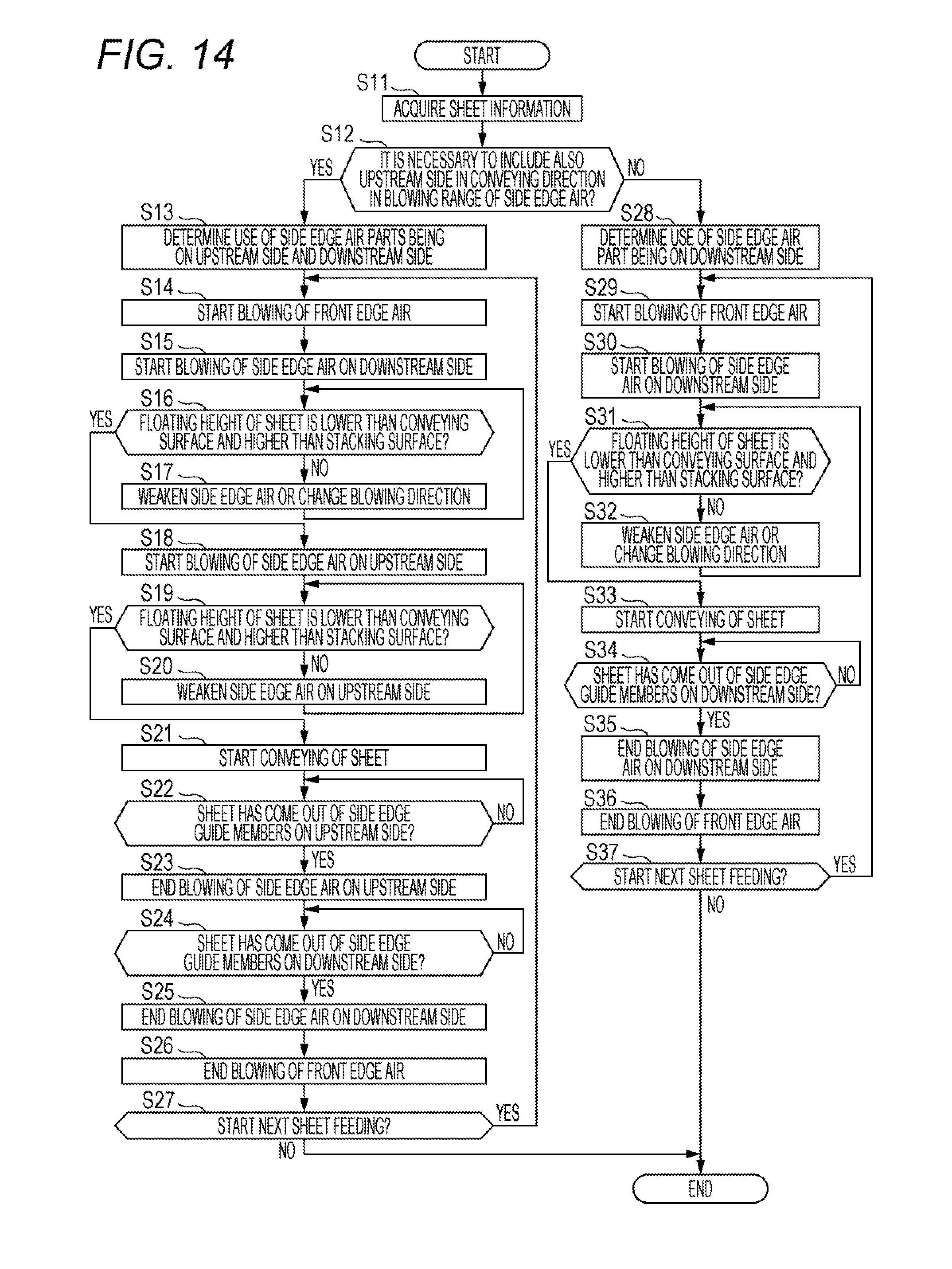
[0040] FIG. 14 is a flowchart illustrating a control example in the embodiment of the present disclosure. In step S11, the controller 200 acquires sheet information. In step S12, the controller 200 determines whether or not it is necessary to include also the upstream side in the conveying direction in a blowing range of the side edge air A. In a case where it is determined that it is necessary to include the upstream side in the conveying direction in the blowing range of the side edge air A (step 912; Y), the controller 200 proceeds to the processing in step S13. The processing in steps S13 to S27 corresponds to a case where the length of the sheet P is equal to or greater than the preset threshold, and corresponds to a case where both the downstream side edge air A_21 and the upstream side edge air A_22 are blown to the sheet P. In a case where it is determined that there is no need to include the upstream side in the conveying direction in the blowing range of the side edge air A (step S12; N), the controller 200 proceeds to the processing in step S28. The processing of steps S28 to S37 corresponds to a case where the length of the sheet P is less than the preset threshold, and corresponds to a case where the downstream side edge air A_21 is blown to the sheet P out of the downstream side edge air A_21 and the upstream side edge air A_22.
[0041] In step S13, use is determined of the side edge air parts 723 being on the upstream side and the downstream side. In step S14, the front edge air part 781 starts blowing of the front edge air A_1. In step S15, the side edge air part 723 being on the downstream side starts blowing of the side edge air A_2 on the downstream side, that is, the downstream side edge air A_21. In step S16, the controller 200 determines whether or not the floating height of the sheet P is lower than the conveying surface S_1 and higher than the stacking surface S_2. In a case where it is determined that the floating height of the sheet P is lower than the conveying surface S_1 and higher than the stacking surface S_2 (step S16; Y), the controller 200 proceeds to the processing in step S18. In a case where it is not determined that the floating height of the sheet P is lower than the conveying surface S_1 and higher than the stacking surface S_2 (step S16; N), the controller 200 proceeds to the processing in step S17. In step S17, the side edge air part 723 weakens the side edge air A_2, specifically, the downstream side edge air A_21, or changes the blowing direction, and the controller 200 returns to the processing in step S16. In step S18, the side edge air part 723 being on the upstream side starts blowing of the side edge air A_2 on the upstream side, that is, the upstream side edge air A_22.
[0042] In step S19, the controller 200 determines whether or not the floating height of the sheet P is lower than the conveying surface S_1 and higher than the stacking surface S_2. In a case where it is determined that the floating height of the sheet P is lower than the conveying surface S_1 and higher than the stacking surface S_2 (step S19; Y), the controller 200 proceeds to the processing in step S21. In a case where it is not determined that the floating height of the sheet P is lower than the conveying surface S_1 and higher than the stacking surface S_2 (step S19; N), the controller 200 proceeds to the processing in step S20. In step S20, the side edge air part 723 being on the upstream side weakens the side edge air A_2 on the upstream side, that is, the upstream side edge air A_22, and the controller 200 returns to the processing in step S19. In step S21, the conveyer 73 starts conveying of the sheet P. In step S22, the controller 200 determines whether or not the sheet P has come out of the side edge guide members 72 on the upstream side. In a case where it is determined that the sheet P has come out of the side edge guide members 72 on the upstream side (step S22; Y), the controller 200 proceeds to the processing in step S23. In a case where it is determined that the sheet P has not come out of the side edge guide members 72 on the upstream side (step S22; N), the controller 200 continues the processing in step S22.
[0043] In step S23, the side edge air part 723 being on the upstream side ends the blowing of the side edge air A_2 on the upstream side, that is, the upstream side edge air A_22. In step S24, the controller 200 determines whether or not the sheet P has come out of the side edge guide members 72 on the downstream side. In a case where it is determined that the sheet P has come out of the side edge guide members 72 on the downstream side (step S24; Y), the controller 200 proceeds to the processing in step S25. In a case where it is determined that the sheet P has not come out of the side edge guide members 72 on the downstream side (step S24; N), the controller 200 continues the processing in step S24. In step S25, the side edge air part 723 being on the downstream side ends the blowing of the side edge air A_2 on the downstream side, that is, the downstream side edge air A_21. In step S26, the front edge air part 781 ends the blowing of the front edge air A_1. In step S27, the controller 200 determines whether or not to start the next sheet feeding. In a case where the controller 200 determines to start the next sheet feeding (step S27; Y), the front edge air part 781 returns to the processing in step S14. In a case where the controller 200 determines not to start the next sheet feeding (step S27; N), the processing is ended.
[0044] In step S28, use is determined of the side edge air part 723 being on the downstream side. In step S29, the front edge air part 781 starts the blowing of the front edge air A_1. In step S30, the side edge air part 723 being on the downstream side starts the blowing of the side edge air A_2 on the downstream side, that is, the downstream side edge air A_21. In step S31, the controller 200 determines whether or not the floating height of the sheet P is lower than the conveying surface S_1 and higher than the stacking surface S_2. In a case where it is determined that the floating height of the sheet P is lower than the conveying surface S_1 and higher than the stacking surface S_2 (step S31; Y), the controller 200 proceeds to the processing in step S33. In a case where it is not determined that the floating height of the sheet P is lower than the conveying surface S_1 and higher than the slacking surface S_2 (step S31; N), the controller 200 proceeds to the processing in step S32. In step S32, the side edge air part 723 weakens the side edge air A_2, specifically, the downstream side edge air A_21, or changes the blowing direction, and the controller 200 returns to the processing in step S31.
[0045] In step S33, the conveyer 73 starts conveying of the sheet P. In step S34, the controller 200 determines whether or not the sheet P has come out of the side edge guide members 72 on the downstream side. In a case where it is determined that the sheet P has come out of the side edge guide members 72 on the downstream side (step S34; Y), the controller 200 proceeds to the processing in step S35. In a case where it is determined that the sheet P has not come out of the side edge guide members 72 on the downstream side (step S34; N), the controller 200 continues the processing in step S34. In step S35, the side edge air part 723 being on the downstream side ends the blowing of the side edge air A_2 on the downstream side, that is, the downstream side edge air A_21. In step S36, the front edge air part 781 ends the blowing of the front edge air A_1. In step S37, the controller 200 determines whether or not to start the next sheet feeding. In a case where the controller 200 determines to start the next sheet feeding (step S37; Y), the front edge air part 781 returns to the processing in step S29. In a case where the controller 200 determines not to start the next sheet feeding (step S37; N), the processing is ended.
[0046] From the above description, according to the present embodiment, the front edge air A_1 and the side edge air A_2 are blown to the sheet P to float the sheet P in a posture in which a portion protruding from the conveyer 73 of the sheet P is lower than the conveying surface S_1 of the conveyer 73. Thus, even if the length of the sheet P is increased, there is no possibility that the sheet P separates from the conveyer 73 and twists on the way. Therefore, stable floating operation can be performed in a non-contact manner while avoiding an increase in size and cost of the apparatus.
[0047] According to the present embodiment, at least one of the strength, blowing position, or blowing direction of the side edge air A_2 is set to float the sheet P in a posture in which the sheet P is lower in the lifting of the sheet P by the upstream side edge air A_22 than in the lifting of the sheet P by the downstream side edge air A_21. Thus, the floating posture of the sheet P can be controlled without direct contact to the sheet P. Therefore, a possibility can be avoided of generating a scratch mark or paper dust on the surface of the sheet P.
[0048] According to the present embodiment, the strength of the upstream side edge air A_22 is set weaker than the strength of the downstream side edge air A_21. Thus, the floating posture of the sheet P can be controlled by the strength of the side edge air A_2. Therefore, an increase in size and cost of the apparatus can be avoided particularly noticeably.
[0049] According to the present embodiment, the position of the side edge air opening 721 of the upstream side edge air A_22 is provided at a lower position in the stacking direction of the sheet P than the position of the side edge air opening 721 of the downstream side edge air A_21. Thus, the floating posture of the sheet P can be controlled with a simple configuration. Therefore, an increase in cost can be avoided particularly noticeably.
[0050] According to the present embodiment, the blowing direction of the upstream side edge air A_22 is set more downward in the stacking direction of the sheet P than the blowing direction of the downstream side edge air A_21. Thus, the floating posture of the sheet P can be controlled by the blowing direction of the side edge air A_2. Therefore, an increase in size and cost of the apparatus can be avoided particularly noticeably.
[0051] According to the present embodiment, the side edge air part 723 changes the amount of blowing of the side edge air A_2 depending on the floating height of the sheet P detected by the side edge detection sensor 724. Thus, the floating height of the sheet P can be controlled to an appropriate position. Therefore, the floating height of the sheet P can be stabilized particularly noticeably.
[0052] According to the present embodiment, the side edge air part 723 stops blowing of the side edge air A_2 in a case where it is detected by the side edge detection sensor 724 that the sheet P has come out of the side edge guide members 72. Thus, excessive rise of the sheet P can be avoided. Therefore, the floating height of the sheet P can be stabilized particularly noticeably.
[0053] Although the image forming system 1 according to embodiments of the present invention have been described and illustrated in detail, the disclosed embodiments are made for purposes of illustration and example only and not limitation. The scope of the present invention should be interpreted by terms of the appended claims. For example, in the present embodiment, an example has been described in which the image forming system 1 includes the sheet feeding apparatus 2 and the image forming apparatus 3; however, the present disclosure is not particularly limited thereto. For example, the image forming system 1 may include an image reading apparatus, a relay apparatus, or a post-processing apparatus. In addition, in the present embodiment, an example has been described in which the sheet feeding apparatus 2 has an external type configuration; however, the present disclosure is not limited thereto. The configuration described in the present embodiment may be applied to the sheet feeding unit 51 in the image forming apparatus 3.
* * * * *
D00000
D00001
D00002
D00003
D00004
D00005
D00006
D00007
D00008
D00009
XML
uspto.report is an independent third-party trademark research tool that is not affiliated, endorsed, or sponsored by the United States Patent and Trademark Office (USPTO) or any other governmental organization. The information provided by uspto.report is based on publicly available data at the time of writing and is intended for informational purposes only.
While we strive to provide accurate and up-to-date information, we do not guarantee the accuracy, completeness, reliability, or suitability of the information displayed on this site. The use of this site is at your own risk. Any reliance you place on such information is therefore strictly at your own risk.
All official trademark data, including owner information, should be verified by visiting the official USPTO website at www.uspto.gov. This site is not intended to replace professional legal advice and should not be used as a substitute for consulting with a legal professional who is knowledgeable about trademark law.