Vacuum Insulated Food Storage Container And Lid
Han; Hongyuan
U.S. patent application number 16/258724 was filed with the patent office on 2019-08-01 for vacuum insulated food storage container and lid. The applicant listed for this patent is BARENTHAL NORTH AMERICA, INC.. Invention is credited to Hongyuan Han.
| Application Number | 20190233177 16/258724 |
| Document ID | / |
| Family ID | 67393152 |
| Filed Date | 2019-08-01 |


View All Diagrams
| United States Patent Application | 20190233177 |
| Kind Code | A1 |
| Han; Hongyuan | August 1, 2019 |
VACUUM INSULATED FOOD STORAGE CONTAINER AND LID
Abstract
Disclosed is a double-wall vacuum-insulated food container with complementary lid. The body of the container has a base and an upwardly-extending side wall terminating in an upper free edge. The container also has an inner portion and a complementary outer portion with a gap between. The lid sealingly fits onto the upper free edge of the container. The lid includes a central member and a surrounding frame with a sealing ring. The sealing ring serves as an interface between a lower peripheral edge of the frame and the upper free edge of the container. The frame has fastening members which complementary features disposed about the upper free edge of the container. Within the container is a separator having an outer profile substantially complementary with an inner contour of the container, whereby the interior of the container may be selectively divided by a user.
| Inventors: | Han; Hongyuan; (New Vernon, CT) | ||||||||||
| Applicant: |
|
||||||||||
|---|---|---|---|---|---|---|---|---|---|---|---|
| Family ID: | 67393152 | ||||||||||
| Appl. No.: | 16/258724 | ||||||||||
| Filed: | January 28, 2019 |
Related U.S. Patent Documents
| Application Number | Filing Date | Patent Number | ||
|---|---|---|---|---|
| 62623206 | Jan 29, 2018 | |||
| Current U.S. Class: | 1/1 |
| Current CPC Class: | B65D 3/00 20130101; B65D 45/22 20130101; B65D 51/1683 20130101; B65D 57/00 20130101; B65D 5/00 20130101; B65D 11/00 20130101; B65D 25/06 20130101; B65D 45/30 20130101; B65D 81/3818 20130101 |
| International Class: | B65D 45/22 20060101 B65D045/22; B65D 3/00 20060101 B65D003/00; B65D 57/00 20060101 B65D057/00 |
Claims
1. A vacuum-insulated container comprising: a body portion, wherein the body portion has a floor and at least one upwardly extending side wall terminating in an upper free edge, and wherein the at least one upwardly extending side wall comprises an inner portion and a complementary outer portion defining a thermally-insulating, side wall gap between; and a lid portion configured to sealingly fit onto the upper free edge, wherein the lid portion comprises a substantially planar member and a frame having sealing ring, wherein the substantially planar member comprises an upper portion and a complementary lower portion defining a thermally-insulating, planar member gap between, wherein the frame is configured to mechanically receive and surround the substantially planar member there within, and wherein the sealing ring is configured to serve as an interface between a lower peripheral edge of the frame and the upper free edge.
2. The vacuum-insulated container of claim 1, further comprising a separator selectively disposed within the vacuum-insulated container, wherein the separator has an outer profile substantially complementary with an inner contour of the vacuum-insulated container, and whereby the interior of the vacuum-insulated container may be selectively divided with the separator.
3. A container comprising: a base having at least one upwardly extending side wall terminating in an upper free edge, wherein the at least one upwardly extending side wall comprises an inner portion and a complementary outer portion defining a thermally-insulating, side wall gap between; a lid configured to fit onto the upper free edge, wherein the lid comprises a substantially planar member and a frame defining a channel, wherein the substantially planar member comprises an upper portion and a complementary lower portion defining a thermally-insulating, planar member gap between, wherein the frame is configured to receive the substantially planar member therewithin; and a sealing member disposed in the channel, wherein the sealing member is configured to create an air-tight seal between a lower peripheral edge of the frame and the upper free edge.
4. The container of claim 3, wherein the base comprises stainless steel, and the substantially planar member comprises of stainless steel.
5. The container of claim 3, wherein the base has one of: a rectangular shape and a square shape.
6. The container of claim 3, further comprising a separator selectively disposed within the container, wherein the separator has an outer profile substantially complementary with an inner contour of the container.
7. The container of claim 6, wherein the separator is configured to span between two parallel sections of the at least one upwardly extending side wall.
8. The container of claim 6, wherein the separator is configured to span between two opposing corners of the at least one upwardly extending side wall.
9. The container of claim 3, wherein the frame further comprises at least one clasp configured to engage a fastening feature on the base.
10. The container of claim 9, wherein the at least one clasp comprises at least one of: a living hinge, a flag hinge and a piano hinge.
11. The container of claim 9, wherein the fastening feature comprises a shoulder and the at least one clasp comprises a prong configured to engage the shoulder.
12. The container of claim 9, wherein the at least one clasp is configured to engage a fastening feature while the lid is maintained relatively stationary with regards to the base.
13. The container of claim 1, wherein the lid portion includes a pressure release valve button configured to, when pressed, equalize an atmosphere within the container and an atmosphere outside the container.
Description
STATEMENT REGARDING FEDERALLY SPONSORED RESEARCH OR DEVELOPMENT
[0001] n/a
BACKGROUND OF THE INVENTION
[0002] Various embodiments relate generally to food storage systems and devices and, more specifically, relate to vacuum-insulated food storage containers with complementary lids.
[0003] This section is intended to provide a background or context. The description may include concepts that may be pursued, but have not necessarily been previously conceived or pursued. Unless indicated otherwise, what is described in this section is not deemed prior art to the description and claims and is not admitted to be prior art by inclusion in this section.
[0004] Maintaining the proper temperature for foods after preparation but before consumption can be difficult. This can be due to small portion size, having a relatively large surface area for radiating or absorbing heat and having a relatively small mass that is insufficient to retain heat or the lack thereof. Further, prior art food storage containers often suffer from inadequate thermal insulative properties. Hot foods quickly become warm or cool and cold foods melt or warm up. Air may be exchanged across a container-lid boundary leading to degradation of the food quality or, worse, contamination. A user's enjoyment of the stored foods is thus inhibited, and the desired freshness may be diminished.
[0005] What is needed is a food storage container and lid having improved thermal and atmospheric sealing performance.
BRIEF SUMMARY OF THE INVENTION
[0006] The below summary is merely representative and non-limiting.
[0007] The above problems are overcome, and other advantages may be realized, by the use of the embodiments.
[0008] In a first aspect, an embodiment provides a double wall vacuum insulated food container with insulated lid that offers superior performance in terms of thermal transfer and atmospheric sealing. The container includes a body portion and a lid portion. The body portion has, in a use configuration, a base or floor and at least one upwardly extending side wall terminating in an upper free edge. The at least one wall may be round, oval, rectangular, square, or any other desired shape. The container comprises an inner portion and a complementary outer portion, there being an air gap in between the two for improved thermal performance. The air gap may be maintained as a vacuum, at low pressure, filled with air, or filled with a preferred gas or combination of gases, or some combination thereof. In one non-limiting embodiment, the air gap may also be filled with a foam insulation. In a preferred embodiment, the container is formed of stainless steel.
[0009] A complementary lid portion is configured to sealingly fit onto the upper free edge of the container. The lid comprises a central substantially planar member and a surrounding frame with sealing ring. The planar member is provided with enhanced thermal characteristics. For example, the planar member may have an upper portion and a lower portion, each being peripherally joined, substantially mutually parallel, and having an air gap there between. The surrounding frame is configured to mechanically receive the planar member there within. The sealing ring serves as an interface between a lower peripheral edge of the frame and an upper free edge of an underlying container. The frame is preferably provided with plural fastening members adapted to selectively engage with complementary features disposed about the upper free edge of the container. In one embodiment, the frame is provided of metal or plastic and the fastening members are connected to the frame, such as through the use of a living hinge.
[0010] Selectively disposed within the container is at least one separator having an outer profile substantially complementary with an inner contour of the container, whereby the interior of the container may be selectively divided by a user.
BRIEF DESCRIPTION OF THE SEVERAL VIEWS OF THE DRAWINGS
[0011] Aspects of the described embodiments are more evident in the following description, when read in conjunction with the attached Figures.
[0012] FIG. 1 is a perspective view of a first embodiment of a vacuum insulated metal food storage container and lid.
[0013] FIG. 2 is an exploded, perspective view of the container of FIG. 1.
[0014] FIG. 3 is a sectional perspective view of the container of FIG. 1.
[0015] FIG. 4 is an exploded, perspective view of the container of FIG. 1.
[0016] FIG. 5 is a perspective view of a second embodiment of the vacuum insulated metal food storage container and lid.
[0017] FIG. 6 is an exploded, perspective view of the container of FIG. 5.
[0018] FIG. 7 is a sectional perspective view of the container of FIG. 5.
[0019] FIG. 8 is an exploded, perspective view of the container of FIG. 5.
[0020] FIG. 9 is a perspective view of another embodiment of the container with clasps in an engaged position.
[0021] FIG. 10 is a perspective view of the container of FIG. 9 with clasps in a rest position.
[0022] FIG. 11 is a detailed elevation view of a portion of the container of FIG. 9 with clasps in the rest position and the engaged position.
[0023] FIG. 12 is a perspective view of the container of FIG. 9 with clasps in a rest position.
[0024] FIG. 13 is a perspective view of the underside of a lid of the container of FIG. 9.
[0025] FIG. 14 is an upside-down perspective view of a portion of the container of FIG. 9.
[0026] FIG. 15 is a perspective view of the body portion of FIG. 9 with a divider.
[0027] FIG. 16 is a perspective view of the body portion of FIG. 9 illustrating insertion of a divider therein.
[0028] FIG. 17 is a perspective view of the body portion of FIG. 9 illustrating manipulation of the divider therein.
[0029] FIG. 18 are plan views illustrating relative dimensions of the container of FIG. 9.
[0030] FIG. 19 is a sectional, elevation view of the container of FIG. 9.
[0031] FIG. 20 is a perspective view of a further embodiment of the container with clasps in an engaged position.
[0032] FIG. 21 is a perspective view of the container of FIG. 20 with clasps in a rest position.
[0033] FIG. 22 is a detailed elevation view of a portion of the container of FIG. 20 with clasps in the rest position and the engaged position.
[0034] FIG. 23 is a perspective view of the container of FIG. 20 with clasps in a rest position.
[0035] FIG. 24 is a perspective view of the underside of a lid of the container of FIG. 20.
[0036] FIG. 25 is an upside-down perspective view of a portion of the container of FIG. 20.
[0037] FIG. 26 is a perspective view of a body portion of FIG. 20 with a divider.
[0038] FIG. 27 is a perspective view of the body portion of FIG. 20 illustrating insertion of a divider therein.
[0039] FIG. 28 are plan views illustrating relative dimensions of the container of FIG. 20.
[0040] FIG. 29 is a sectional, elevation view of the container of FIG. 20.
[0041] FIG. 30 is an elevation view of a clasp suitable for use in either of the containers of FIGS. 1, 5, 9, and 20.
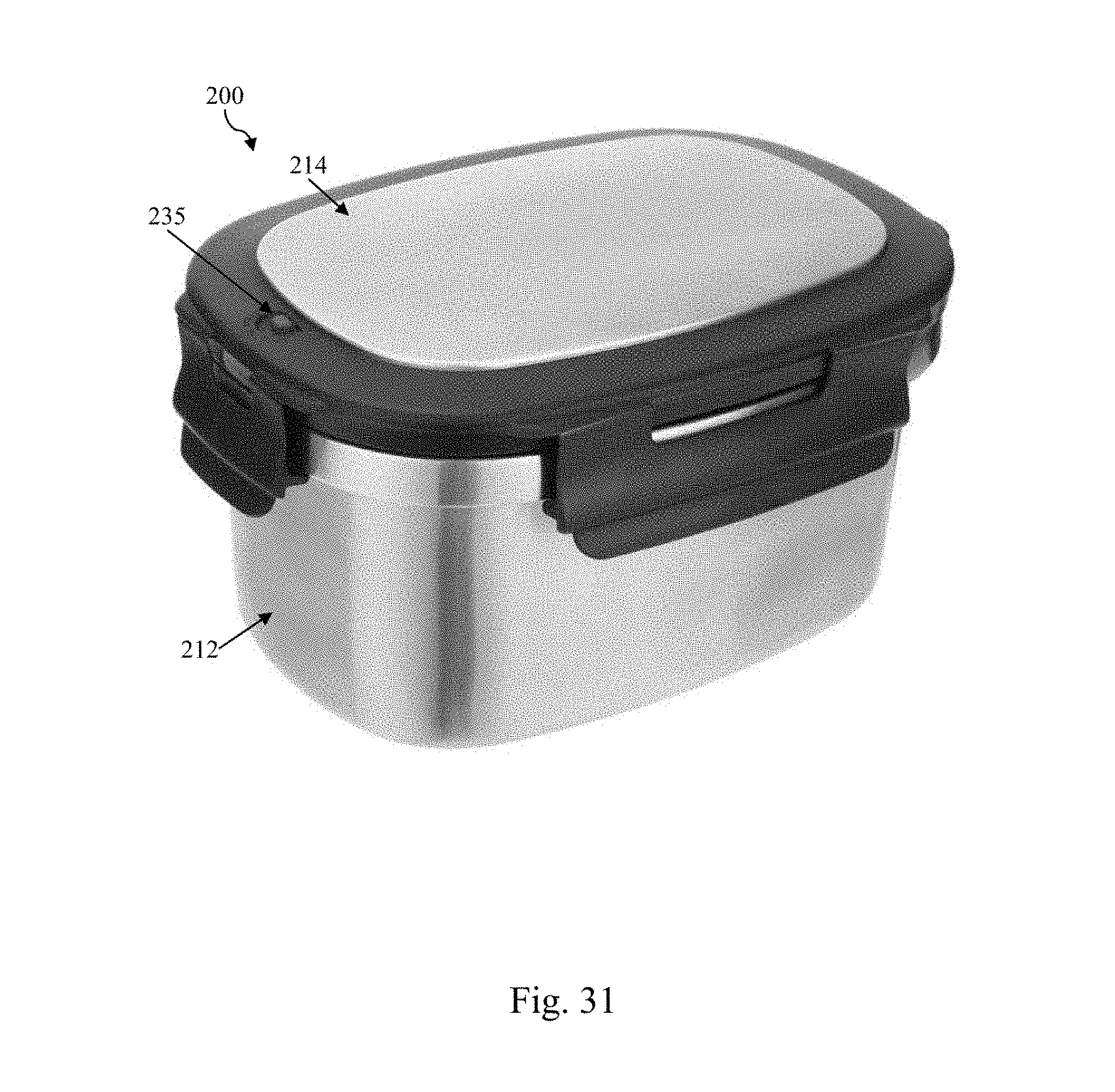
[0042] FIG. 31 is a perspective view of an embodiment of a container with a pressure release valve.
[0043] FIG. 32 is a closeup view of a portion of the lid of the container of FIG. 31.
DETAILED DESCRIPTION OF THE INVENTION
[0044] This patent application claims priority from U.S. Provisional Patent Application No. 62/623,206, filed Jan. 29, 2018, the disclosure of which is incorporated by reference herein in its entirety.
[0045] FIGS. 1 and 5 depict a double wall vacuum insulated food container 10 with insulated lid 14, according to the present disclosure. The container 10 comprises a body portion 12 and an insulated lid portion 14 configured to sealingly mate with the body portion 12.
[0046] With respect to FIGS. 3, 4, 7, and 8, the body portion 12, in a use configuration, has a base or floor 16 and at least one upwardly extending side wall 18 terminating in an upper free edge 20.
[0047] Preferably, the upper free edge 20 is equidistant from the base 16 along all points about the container 10. However, in certain embodiments, it may be desirable to have one or more discontinuities or regions where the distance from the base 16 to the upper free edge 20 is not uniform.
[0048] The at least one upwardly extending side wall 18 can be provided in a variety of vertical projections, including round, oval, square, rectangular, or other geometries. For example, there may be four such walls 18 arranged in the shape of a square with two pairs of oppositely facing, mutually parallel walls, as depicted in FIGS. 5-8 and 20-29. In particular, with respect to FIG. 28, the length and width, dimensions L and W, are equal. In an exemplary embodiment, L and W equal 176 mm and the container height, dimension H, equals 81 mm. Alternatively, there may be four such walls 18 arranged in the shape of a rectangle with two pairs of oppositely facing, mutually parallel walls 18, as depicted in FIGS. 1-4 and 9-19. In particular, with respect to FIG. 18, the length is 176 mm and the width is 126 mm, while the container height is 81 mm. The transitions between adjacent walls 18 and between the base 16 and the side walls 18 in all configurations may be ninety degrees or rounded (as illustrated) with a desired radius.
[0049] The body portion 12 in a first embodiment is provided of stainless steel due to its superior cleanability and thermal qualities. An outer surface of the container 10, when provided of stainless steel, may be polished or brushed, the latter enabling easier gripping, particularly in damp or wet environments. In the first embodiment, the stainless steel is 0.5 mm thick.
[0050] In one embodiment, the floor 16 is flat and featureless. However, in other embodiments, the base 16 may be provided with linear or discrete features 26 (FIGS. 3 and 7) which may resist a tendency for the container 10 to adhere to or slide along a wet surface such as a kitchen counter. Such features 26 provided on the bottom of the container 10 may also be configured to fit cooperatively with complementary features on the top of a corresponding lid 14 (not shown) to facilitate vertical stacking of body/lid units. Such features 26 may also include downward projections on the container floor 16 and/or complementary recesses on the lid 14 upper surface. Further, the floor exterior surface may also have a depression or aperture 48 used to evacuate air during the manufacturing process, as shown in FIGS. 3 and 7. Once the space between the inner wall 22 and the outer wall 24 is evacuated, in an illustrated embodiment, the aperture 48 is plugged. For purposes of presentation, the sealed aperture 48 may be covered, as with a cap or cover 49.
[0051] Preferably, the body portion 12, including the floor 16 and at least one side wall 18, is comprised of an inner wall 22 and an outer wall 24 (FIGS. 3, 7, 19, and 29), each of which are substantially mutually parallel and joined at the upper free edge 20. The space between the inner and outer walls 22, 24 is evacuated in a first embodiment to create a vacuum to improve the resistance to thermal transfer of the body portion 12. In combination therewith or in the alternative, the space between the inner and outer walls 22, 24 may contain a low-pressure quantity of air and/or one or more desired gases.
[0052] At the upper free edge 20 of the body portion 12, the outer wall 24 forms an outwardly projecting shoulder 30, as seen at least in FIGS. 4, 8, 11, 14, 22, and 25. As will be described, this shoulder 30 receives part of the lid portion 14 and prevents the lid portion 14 from resting on the body portion 12 at an angle.
[0053] As shown with respect to the embodiments of FIGS. 2 and 6, the lid portion 14 comprises a central substantially planar member 40 and a surrounding frame 42 with sealing member 44. The planar member 40 may be completely flat and featureless, as shown in FIGS. 9, 10, 20, and 21. Alternatively, the planar member 40 may have a variety of physical features formed therein for functional and/or decorative purposes, such as seen in FIGS. 1 and 5. For example, the planar member 40 may be provided with recesses that physically complement downwardly projecting features 26 disposed on the outer surface of the body portion floor 16, as previously described. Such complementary features 26 may facilitate vertical stacking of body/lid units.
[0054] The planar member 40 is preferably provided of stainless steel due to its superior cleanability and thermal qualities. The planar member 40 is also preferably hollow, having an upper surface 50, a lower surface 52, and a surrounding side wall 54 formed into a single, hollow unit, as shown in FIGS. 19 and 29. The interior of the planar portion 40 may be provided as a vacuum, may contain low pressure air, and/or may contain one or more desired gases, to enhance the resistance to thermal transfer through the lid portion 14.
[0055] About a lower edge of the periphery of the planar member 40, at the juncture of the lower surface 52 and the side wall 54, is an inwardly extending shoulder 56. This shoulder 56 preferably extends continuously about the entire planar member 40.
[0056] The frame 42 may be formed of plastic or metal, though plastic may be preferred in some embodiments due to its lower weight, pliability and resistance to denting, and ability to be provided in a variety of colors. The frame 42 is preferably provided with a substantially vertical, inwardly facing side wall 60 that forms a continuous enclosed space dimensioned to snugly receive the planar member 40. Formed at a lower extent of the side wall 60 is an inwardly projecting shelf 62 dimensioned to complement the dimensions of the inwardly extending shoulder 56 of the planar member 40. The inwardly extending shoulder 56 of the planar member 40 thus rests on the inwardly projecting shelf 62 of the frame 42 and is retained there through interference fit in a first embodiment. In alternative embodiments, the planar member 40 is retained within the frame 42 via gluing, welding, and/or mechanical features or means.
[0057] As shown in FIGS. 9-11 and 20-22, the frame 42 is provided with a plurality of peripherally disposed clasps 70. In the illustrated embodiments, there is one clasp 70 associated with each of the at least one side walls 18. Thus, in the depicted embodiments, there are a total of four clasps 70. Preferably, each clasp 70 extends laterally across a portion of the frame 42. As illustrated in FIGS. 11 and 22, the clasps 70 are attached to the frame 42 via a hinge 72. The hinge 72 in a first embodiment is a plastic living hinge. Other, more complex hinges, such as flag hinges or piano hinges, may be employed, though with added complexity and increased difficulty in maintaining cleanliness.
[0058] In a first, rest position, shown in FIGS. 10 and 21 and on the left side of FIGS. 11 and 22, the clasps 70 may extend outwardly from the lid portion 14 about the respective hinge 72. In a second, engaged position, shown in FIGS. 9 and 20 and on the right side of FIGS. 11 and 22, each clasp 70 may be manually manipulated into the engaged position in which the respective clasp 70 extends substantially vertically, adjacent the lid portion 14 and the body portion 12. On an inner side of the clasp 70, most proximate the body portion 12 when the lid portion 14 is mounted thereon, the clasp 70 has a prong 76. When the clasp 70 is in the engaged position, the prong 76 projects upward at an angle from the clasp 70. As seen in FIG. 30, with the respective clasp 70 angled around the hinge 72 to the engaged position, the prong 76 extends slightly upwardly, forming an oblique angle 78 with respect to a portion of the clasp 70 below the prong 76 (indicated by a dashed arc) and forming an acute angle with respect to a portion of the clasp 70 above the prong 76 (also indicated by a dashed arc). Thus, when the lid portion 14 is lowered onto the body portion 12, the lower surface of the prong 76 may deflect away from the outwardly projecting shoulder 30 atop the upper free edge 20 of the outer wall 24. Once the lid portion 14 is fully seated on the upper free edge 20, as discussed subsequently, the clasp 70 may be manually urged into the engaged position, which by an upwardly projecting point 82 of the prong 76 contacts a lower surface of the outwardly projecting shoulder 30, effectively restraining upward vertical movement of the lid 14. The clasp 70 is removed from the engaged position by a user inserting one or more fingers on a lower extent of the clasp 70 and/or on an inside edge of the lower extent of the clasp 70 and pulling outwardly. The upwardly projecting point 82 of the prong 76 is thus removed from engagement with the outwardly projecting shoulder 30 and the clasp 70 may swing or be swung about the hinge 72 to the rest position. Note that in the illustrated embodiment the clasp 70 has a substantially vertical upper portion 90 and an angled lower portion 92 that is angled slightly outwardly, opposite the respective prong 76. Such a configuration enhances the ability of a user to engage the clasp 70 when moving it from the engaged position to the rest position. In an alternative embodiment, the clasp 70 is substantially planar.
[0059] The prong 76 associated with each clasp 70 may be a discrete element that has a narrow width with respect to the respective clasp 70. Alternatively, the prong 76 may have a width that is a greater percentage of the width of the respective clasp 70, all the way up to 100% of the respective clasp width. In the embodiments of FIGS. 13 and 24, the prongs 76 are seen to extend over a major length of the respective clasp 70.
[0060] The lower extent of the frame 42 is provided with a peripheral, downwardly facing channel 94, as seen in FIGS. 3 and 7. Disposed within the channel 94 is the sealing member 44, which in a first embodiment is provided of silicone, though other pliant, resilient materials may be employed. Thus, as viewed in FIGS. 3 and 7, when the lid portion 14 is disposed atop the body portion 12, the sealing member 44 rests on top of the upper free edge 20 of the at least one side wall 18. Preferably, a user applies downward force on the lid portion 14 in order for the upwardly projecting point 82 of the prongs 76 associated with each clasp 70 to fit beneath the outwardly projecting shoulder 30 atop the upper free edge 20 of the outer wall 24. The sealing member 44 thus deforms slightly, forming an airtight seal with the upper free edge 20. Once the clasp 70 is returned to the rest position and the lid portion 14 is removed from the body portion 12, the sealing member 44 returns to an uncompressed shape.
[0061] Optionally, the food container 10 may include a body portion divider 100a, 100b (FIGS. 2 and 6). For ease of cleaning and for reduced cost, the divider 100a, 100b is preferably provided in plastic. Each divider 100a, 100b includes a pair of parallel, vertically extending end walls 102 and a vertical intermediate wall 104 disposed between and orthogonal to the respective end walls 102 (FIGS. 4 and 8). The dimensions of the divider 100a, 100b depend in part upon the dimensions of the respective body portion 12 and in part upon how the divider 100a, 100b is to cooperate with respect to the body portion 12.
[0062] For example, the divider 100a is configured to extend across a width of the respective body portion 12. The end walls 102 are planar. Both the end walls 102 and the intermediate wall 104 are dimensioned in this embodiment to span the width of the body portion 12, as seen in FIG. 15. Preferably, the intermediate wall 104 is long enough so that the divider 100a is installed and retained in the body portion 12 through a friction fit, such as seen in FIG. 16. However, the fit enables the divider 100a to be moved along the length dimension of the body portion 12 according to the needs of the user, as seen in FIG. 17. Also visible in this embodiment is a divider bottom wall 106 that substantially lies in a horizontal plane, orthogonal to the intermediate wall 104. Once installed in the respective body portion 12, the bottom wall 106 lies flush against the floor 16.
[0063] In another embodiment, the divider 100b is configured and dimensioned to fit vertically, on the diagonal between opposite corners of a four-sided body portion 12, such as the square body portion 12 seen in FIGS. 26 and 27. The end walls 102 are curved to complement the interior curvature between the at least one side walls 18. The divider 100b is also provided with a bottom wall 106. Once inserted, the divider 100b effectively separates two halves of the body portion 12.
[0064] FIGS. 31 and 32 show a view of a further embodiment of a container 200. In this embodiment, the container 200 has a body 212 and a lid 214. The lid 214 includes a pressure release valve 235. When hot foods are placed inside the container 200 and the lid 214 is sealed the heat can cause a pressure differential between the interior and exterior atmospheres. This can make separating the lid 214 from the body 212 difficult. By pressing the pressure release button 235, the interior container atmosphere is equalized to the exterior atmosphere, allowing the lid 214 to be easily removed from the container body 212.
[0065] The foregoing description has been directed to particular embodiments. However, other variations and modifications may be made to the described embodiments, with the attainment of some or all of their advantages. Modifications to the above-described systems and methods may be made without departing from the concepts disclosed herein. Accordingly, the invention should not be viewed as limited by the disclosed embodiments. Furthermore, various features of the described embodiments may be used without the corresponding use of other features. Thus, this description should be read as merely illustrative of various principles, and not in limitation of the invention.
LIST OF REFERENCE NUMBERS
[0066] 10 container [0067] 12 body portion [0068] 14 lid portion [0069] 16 base or floor [0070] 18 side wall [0071] 20 upper free edge [0072] 22 inner wall [0073] 24 outer wall [0074] 26 linear or discrete features [0075] 30 outwardly projecting shoulder [0076] 40 planar member or portion [0077] 42 frame [0078] 44 sealing member [0079] 48 depression or aperture [0080] 49 cap or cover [0081] 50 upper surface [0082] 52 lower surface [0083] 54 side wall [0084] 56 inwardly extending shoulder [0085] 60 inwardly facing side wall [0086] 62 inwardly projecting shelf [0087] 70 clasps [0088] 72 hinge [0089] 76 prong [0090] 78 oblique angle [0091] 82 upwardly projecting point [0092] 90 substantially vertical upper portion [0093] 92 angled lower portion [0094] 94 peripheral, downwardly facing channel [0095] 100a body portion divider [0096] 100b body portion divider [0097] 102 parallel, vertically extending end walls [0098] 104 vertical intermediate wall [0099] 106 divider bottom wall [0100] 200 container [0101] 212 body portion [0102] 214 lid portion [0103] 235 pressure release valve
* * * * *
D00000
D00001
D00002
D00003
D00004
D00005
D00006
D00007
D00008
D00009
D00010
D00011
D00012

D00013

D00014

D00015

D00016
D00017

XML
uspto.report is an independent third-party trademark research tool that is not affiliated, endorsed, or sponsored by the United States Patent and Trademark Office (USPTO) or any other governmental organization. The information provided by uspto.report is based on publicly available data at the time of writing and is intended for informational purposes only.
While we strive to provide accurate and up-to-date information, we do not guarantee the accuracy, completeness, reliability, or suitability of the information displayed on this site. The use of this site is at your own risk. Any reliance you place on such information is therefore strictly at your own risk.
All official trademark data, including owner information, should be verified by visiting the official USPTO website at www.uspto.gov. This site is not intended to replace professional legal advice and should not be used as a substitute for consulting with a legal professional who is knowledgeable about trademark law.