Method For Treating Neurological Disorders, Including Tumors, With Electroporation
LATOUCHE; EDUARDO ; et al.
U.S. patent application number 16/210771 was filed with the patent office on 2019-08-01 for method for treating neurological disorders, including tumors, with electroporation. The applicant listed for this patent is CHRISTOPHER ARENA, RAFAEL DAVALOS, LUCY EPSHTEYN, EDUARDO LATOUCHE, SAMUEL LESKO, MELVIN LORENZO, JOHN ROSSMEISL. Invention is credited to CHRISTOPHER ARENA, RAFAEL DAVALOS, LUCY EPSHTEYN, EDUARDO LATOUCHE, SAMUEL LESKO, MELVIN LORENZO, JOHN ROSSMEISL.
| Application Number | 20190232048 16/210771 |
| Document ID | / |
| Family ID | 67392682 |
| Filed Date | 2019-08-01 |


View All Diagrams
| United States Patent Application | 20190232048 |
| Kind Code | A1 |
| LATOUCHE; EDUARDO ; et al. | August 1, 2019 |
METHOD FOR TREATING NEUROLOGICAL DISORDERS, INCLUDING TUMORS, WITH ELECTROPORATION
Abstract
This disclosure describes the methods, devices, and systems of treating diseased tissue with integrated nanosecond pulse irreversible electroporation. Methods and systems as disclosed provide MRI compatible shielded electrodes and electrode leads to prevent emanating radiofrequency noise and improve image quality, disconnecting the electrode from the cable linkage to the pulse generator reduce electromagnetic interference and image artifacts, placing electrodes strategically within a guide cannula to minimize distortion from heterogeneities or maximize ablation within the tissue, utilizing conductive fluids, innate or external, such as cerebral spinal fluid or grounding pads to provide a pathway for current return, and for timing of the electrical waveforms with inherent brain electrical activity.
| Inventors: | LATOUCHE; EDUARDO; (CHELSEA, MA) ; LESKO; SAMUEL; (BLACKSBURG, VA) ; EPSHTEYN; LUCY; (BLACKSBURG, VA) ; ARENA; CHRISTOPHER; (BLACKSBURG, VA) ; ROSSMEISL; JOHN; (BLACKSBURG, VA) ; LORENZO; MELVIN; (BLACKSBURG, VA) ; DAVALOS; RAFAEL; (BLACKSBURG, VA) | ||||||||||
| Applicant: |
|
||||||||||
|---|---|---|---|---|---|---|---|---|---|---|---|
| Family ID: | 67392682 | ||||||||||
| Appl. No.: | 16/210771 | ||||||||||
| Filed: | December 5, 2018 |
Related U.S. Patent Documents
| Application Number | Filing Date | Patent Number | ||
|---|---|---|---|---|
| 62595041 | Dec 5, 2017 | |||
| Current U.S. Class: | 1/1 |
| Current CPC Class: | A61B 18/1477 20130101; A61N 1/327 20130101; A61N 1/0529 20130101; A61N 1/3718 20130101; A61B 2018/00613 20130101; A61B 2018/00321 20130101; A61N 1/086 20170801; A61B 2018/00875 20130101; A61N 1/36171 20130101 |
| International Class: | A61N 1/05 20060101 A61N001/05; A61N 1/36 20060101 A61N001/36; A61N 1/37 20060101 A61N001/37; A61N 1/32 20060101 A61N001/32 |
Claims
1. A nanosecond pulse irreversible electroporation system for ablating tissue during simultaneous operation of MRI equipment, said system comprising: a pulse generator; a plurality of electrodes locatable in the tissue to be ablated, said plurality of electrodes connected to the pulse generator; and a shielding material intermediate said plurality of electrodes and said MRI equipment to prevent electromagnetic interference with operation of the MRI equipment.
2. The system of claim 1, further comprising: said plurality of electrodes comprising at least one monitoring electrode providing real-time measurement of tissue impedance.
3. The system of claim 1, further comprising: said at least one monitoring electrode comprising a sensor electrode array.
4. The system of claim 1, further comprising: said plurality of electrodes comprising a temperature probe.
5. The system of claim 1, further comprising: insulative material along at least one of said plurality of electrodes, said insulative material positioned between said at least one of said plurality of electrodes and protected tissue structure to be protected by directing current away from said protected tissue structure.
6. The system of claim 1, further comprising: an external grounding pad in electrical communication with the plurality of electrodes to direct current away from the protected tissue structure.
7. The system of claim 1, further comprising: electrical communication provided by a fluid electrode in communication with a conductive probe in a region of tissue.
8. The system of claim 1, further comprising: said pulse generator controlling pulse timing to minimize effect on neuronal networks.
9. The system of claim 1, further comprising: a train of high-frequency, biphasic pulses, in which the phase delay between pulses of alternating polarity is controlled in relation to nerve desynchronization.
10. The system of claim 8, further comprising: said pulse generator providing electrical stimulation to create a latency period in neuronal activity, during which electroporation pulses are administered.
11. The system of claim 1, further comprising: said pulse generator synchronizing delivery of electroporation pulses in relation to recording of inherent or evoked electric potentials.
12. The system of claim 1, further comprising: a cannula configured for selectively locating an electrode in tissue.
13. The system of claim 1, further comprising: said pulse generator comprising application software in communication with a voltage generator to provide said waveforms.
14. The system of claim 1, further comprising: said electrode comprising nickel titanium.
15. The system of claim 1, further comprising: said plurality of electrodes including an insert comprising MRI contrast material to provide visible indication of probe location.
16. The system of claim 1, further comprising: said plurality of electrodes located to minimize distortion from heterogeneities.
16. The system of claim 1, further comprising: said plurality of electrodes located to maximize ablation of tissue.
17. A method for ablating tissue, said method comprising operating the system of claim 1.
18. The system of claim 1, further comprising: a metal rod; a wire connection; a wire disconnection; an insulation handle; an electrode handle; a stopper/set-screw; a cranial bolt with adjustable angel/trajectory.
19. A method for ablating tissue, said method comprising operating the system of claim 1.
20. A method for ablating tissue by placing a plurality of electrodes of a cannula-based electrode system, comprising the steps of: a. creating a burr hole under MRI guidance; b. mounting a guide cannula to the skull; c. inserting a shielded electrode into said guide cannula; d. inserting a portion of said guide cannula into the brain by operation of a controllable mechanical device; e. placing said shielded electrode by said guide cannula in an electrode location; f. connecting each of said shielded electrodes to a shielded lead; g. connecting each shielded lead to the function pulse generator; and h. operating a function generator to synchronize pulses with inherent brain electrical activity during the delivery of the pulses.
21. The method of claim 20, comprising: selecting a plurality of electrode locations to minimize distortion from heterogeneities, maximize ablation, or both.
22. The method of claim 20, wherein the guide cannula can act as insulation.
23. The method of claim 20, wherein the electrodes are comprised of one or more electrical conductors, one possibly being a grounding pad, surrounding the target site.
24. The method of claim 20, wherein the brain refractory period may be linked with the pulse generator to ensure maximum safety during treatment.
25. The method of claim 20, wherein the control of directional ablation is used during treatment.
26. The method of claim 20, wherein the electrodes and cannula are MRI compatible and arranged to minimize artifact by using Nickel Titanium for the probe and having MRI compatible electrode connections, with the ability to reach outside of the MRI suite.
27. The method of claim 22, wherein the cannula uses the following materials as its main composition: polyimide, Teflon, or PEEK.
28. The method of claim 22, wherein the cannula insulates non-symmetrical surface areas of the electrode to generate electric field distortions favorable to the target ablation.
29. The method of claim 20, wherein a counter electrode is a dispersive electrode or ground pad strategically to orient high electric fields in a favorable direction.
30. The method of claim 20, wherein the ablating electrodes acts as both the ablation device and the electrophysiological sensor.
31. The method of claim 20, wherein at least one electrode configured for reversibly or irreversibly electroporating tissue and monitoring electrical activity.
32. The method of claim 20, wherein electrophysiological data is incorporated in treatment planning for electroporation procedures.
33. The method of claim 20, wherein a needle-electrode and a ground pad are used.
34. The method of claim 33, wherein bulk tissue electrical resistances local to the needle-electrode and ground pad are modified to maximize an area of treatment.
35. The method of claim 33, wherein all electrodes involved in the ablation area are cooled down to minimize increases in tissue conductivity near needle-electrodes.
36. The method of claim 33, wherein a fluid of low conductivity is delivered in the vicinity of the needle-electrode to prevent increases in electric field magnitude near the dispersive electrode resulting in larger ablations near the needle-electrode and minimizing muscle stimulation.
37. The method of claim 33, wherein the direction of current is away from ventricles.
38. A method for ablating tissue of using a physical or electrical switching mechanism within electrode connections.
39. The method of claim 38, wherein a physical disconnect of the electrode cables exists between the MRI suite and control room as well as directly before the electrodes.
40. The method of claim 38, wherein an electrical disconnect of the electrode cables exists between the MRI suite and control room as well as directly before the electrodes.
41. The method of claim 38, wherein an electrical disconnect is applied that could include but is not limited to a physical switch, relay switch, and or software switch.
42. The method of claim 38, wherein an electrical or physical switching mechanism is used that may be controlled by human or robotic systems.
43. A method for ablating tissue, said method comprising: using semi-conductive material for electrode conductive material.
44. The method of claim 43, wherein the electrode conductive material is a semiconductor.
Description
FIELD OF THE INVENTION
[0001] The present disclosure relates to the use of electroporation for treatment of diseased tissue within the brain, head, neck, and spinal cord in relation to treatment of diseases and disorders. The present disclosure relates more specifically to devices and methods for destroying aberrant cell masses, including tumor tissues, with use of waveforms capable of inducing electroporation. The disclosure also relates to procedures to enhance the safety and treatment outcomes of electroporation intervention. The present disclosure also relates to electroporation with placement of electrodes to minimize distortion from heterogeneities, maximize ablation within tissue, or both, such as by placement of electrodes within a guide cannula. The disclosure also relates to electroporation with a function generator operable to deliver pulse parameters desired for such procedures, and a function generator configurable for such operation.
BACKGROUND
[0002] The Central Brain Registry of the United States (CBTRUS) estimates that 79,270 Americans may be diagnosed with primary malignant (26,070) and primary non-malignant (53,200) brain and central nervous system (CNS) tumors in 2017. Additionally, it is estimated that 20-40% of all other cancers (.about.250,000) including lung, breast, melanoma, colon, and kidney eventually metastasize to the brain. Gliomas are primary tumors that arise from glial cells that normally support and protect neurons in the brain and the CNS. Gliomas represent about 80% of all primary malignant brain tumors with an estimated annual incidence of 20,856 Americans in 2017. Unfortunately, Glioblastoma Multiforme (GBM=grade IV astrocytoma) accounts for 55.1% (12,120 Americans) of all malignant gliomas (MG) making it the most common and deadliest brain tumor. Despite efforts to defeat malignant glioma, 16,947 Americans may die from primary malignant brain and other CNS tumors in 2017. Thus, there is a dire need for new technologies that may alter the course of malignant brain tumor treatment and improve survival and quality-of-life of patients suffering from this and other deadly diseases.
[0003] The incidence of aggressive brain malignancies is increasing, in part due to the aging population in the US. The poor prognosis for MG patients results from a lack of effective targeted therapies combined with the failure of chemotherapies to penetrate the diffuse tumor infiltrative niche that causes recurrence. A treatment approach using electric field-based cell-selective tumor ablation may lead to more effective MG treatment. Primary brain tumors, such as MG, are commonly treated through surgery, radiation therapy, and/or chemotherapeutic regimens. Even when using aggressive and often debilitating therapies, cure rates have not improved. Regrowth of the primary tumor is virtually inevitable. Nearly all patients with MG develop tumor resistance to treatment with rapid case progression. One of the main reasons for poor survival is migration and continued growth of glioma cells several centimeters beyond the margins of the observable tumor. These distant, infiltrating cells are a key factor in tumor progression and resistance to therapy.
[0004] Irreversible electroporation (IRE) is a tumor treatment method for tissue ablation that does not require elevating the tumor to lethal temperatures to achieve lasting therapeutic effects. An example is disclosed in U.S. Pat. No. 8,992,517B2 to Davalos et al. The IRE technique uses microsecond-long (.about.100 .mu.s) electric pulses, applied with minimally invasive electrodes in the targeted region to generate electric fields in excess of 1000 V/cm and kill tissue. This ablation modality is capable of killing cells in large volumes (>50 cm.sup.3) without inducing thermal damage to essential tissue components, such as extracellular matrix, blood vessels, and nerves from damage. Recently, IRE has been shown to nearly double the median survival of patients diagnosed with stage III pancreatic cancer (from 6-13 months to 24.9 months).
[0005] IRE systems and methods using bipolar pulses also may be used for treatment of neurological disorders. Such systems and methods are disclosed in U.S. Pat. No. 8,926,606B2, U.S. Pat. No. 8,992,517, and US20160338758. A suitable commercially available system, for example, is the H-FIRE.TM. Integrated Nanosecond Pulsed IRE system available from the present applicant (Voltmed Inc., Blackburg, Va.). In such an Integrated Nanosecond Pulsed IRE system, the relatively long (.about.100 .mu.s) IRE electrical pulses are replaced with bursts of ultrashort (.about.0.5-2 .mu.s) bipolar pulses. This change improves procedural safety, as a minimally invasive procedure may be performed without neuroparalytic agents. There is a latency period between the delivery of a single monophasic pulse and the firing of an action potential. Delivering an alternating polarity pulse within this latency period (.about.100 .mu.s) may accelerate membrane repolarization and inhibit action potential generation. Electroporation still occurs, as the time course for pore formation is significantly faster (.about.500 ns). An Integrated Nanosecond Pulsed IRE system has been used to safely perform electroporation treatment without neuroparalytic agents on three (3) canine patients with brain tumors.
[0006] An Integrated Nanosecond Pulsed IRE system may be tuned to provide selective cancer cell ablation within the normal brain tissue that surrounds MG. Malignant cells may exhibit an enlarged nucleus-to-cytoplasm ratio (NCR), and the Integrated Nanosecond Pulsed IRE system may be tuned to provide a frequency of polarity changes to maximize the transmembrane potential on the plasma membrane according to this geometrical consideration. It is believed that close proximity of the nuclear membrane to the plasma membrane in malignant cells may promote rapid charging of the plasma membrane when high-frequency waveforms are applied, and that electroporation may be achieved at a lower electric field compared to healthy cells. Given the poor prognosis of aggressive MG, new methods capable of destroying MG without damaging surrounding critical vascular structures are desired.
BRIEF SUMMARY OF THE INVENTION
[0007] The present disclosure provides improved Integrated Nanosecond Pulsed IRE systems and apparatus, and improved methods for performing Integrated Nanosecond Pulsed IRE. In embodiments, for example, an Integrated Nanosecond Pulsed IRE system may include electrodes which are compatible and usable with simultaneous operation of MRI equipment. Such an Integrated Nanosecond Pulsed IRE system, which is compatible and usable with simultaneous operation of MRI equipment, may provide visibility of the electrodes and may enable the procedure and placement of the electrodes in an accurate, precise manner. In embodiments, improved control of placement of electrodes may provide improved electroporation of target tissue and improved selectivity by avoiding undesired electroporation of surrounding, non-target tissue. With MRI guidance before and during the procedure, the treatment may be monitored as well as changed during the procedure, if needed. In embodiments, such a system may be configured to provide synchronization of the guide cannula, pulses, or both, with inherent brain electrical activity. Such synchronization may enable minimizing distortion from heterogeneities, may maximize ablation within the tissue, and may enable improved accuracy in placement of the electrodes, and thus may provide more accuracy in defining or differentiating the treatment area or target area of tissues from surrounding, non-target tissues. In embodiments, such a system may include capability for the electrode to be disconnected from a cable linkage to a pulse generator with reduction of electromagnetic interference, image artifacts, or both. In embodiments, a method for performing Integrated Nanosecond Pulsed IRE may include disconnecting the electrode from a cable linkage to a pulse generator with reduced or limited electromagnetic interference, image artifacts, or both.
[0008] The present disclosure provide a method of electroporation treatment of diseased tissue, with improved safety and with improved treatment outcomes of electroporation therapy. Embodiments may include a method of making an electrode for an electroporation system, that is compatible and usable with simultaneous operation of MRI equipment. In embodiments, a method of electroporation may include operating an electroporation system having an electrode compatible and usable with simultaneous operation of MRI equipment, for administering electroporation therapy. In embodiments, such a method may include shielding the electrode leads to prevent electromagnetic interference of the leads, the electrode, or both, with MRI equipment in operation with the electroporation system. In embodiments, a method for electroporation may include operating manual switches, electronic switches, or both, to prevent or reduce emanating radiofrequency noise to MRI equipment, and to improve MRI image quality. In embodiments, such a method may include utilizing tissue property measurements, drug delivery systems, or both, in combination with an MRI-compatible electroporation electrode, to enable placement of one or plural electroporation electrodes in tissue at selected electrode location(s) within a guide cannula. In embodiments, such a method may include placement of one or plural electroporation electrodes in tissue, at selected location(s) within a guide cannula, to minimize distortion from heterogeneities or maximize ablation within the tissue. In embodiments, such a method may utilize conductive fluids, innate or external, such as cerebral spinal fluid, or grounding pads, to provide a pathway for current return, and for timing of the electrical waveforms with inherent brain electrical activity to enhance safety and treatment outcomes for a patient undergoing an electroporation procedure. Methods of electroporation as disclosed herein may be used for treatment of any ailment(s) within the brain, head, neck and spinal cord that may be treated with electroporation. Ailments treated by methods of electroporation may include, without limitation, cancer, disorders, tumors, essential tremors, and Parkinson's disease.
[0009] Methods of electroporation disclosed herein may provide electroporation waveforms for treatment of cancers, brain disorders and tumors via tissue ablation in combination with immunotherapeutic agents, immunotherapeutic agents, chemotherapy, and for blood-brain-barrier disruption. Methods disclosed herein may include producing bursts of monophasic or biphasic pulses for treatment of tumors, alone or in combination with immunotherapeutic agents and chemotherapy. Methods of electroporation disclosed herein may include operating an MRI-compatible electroporation probe with a grounding pad to deliver pulsed electric fields, either alone or in combination with one or a plurality of molecular agents. Such molecular agents may include, for example, chemotherapy, gene-therapy, and tumor-associated antigens. Methods of electroporation disclosed herein may provide, for example, reversible electroporation for electrogene therapy, electrochemotherapy, and electroporation to induce immune response. Methods of electroporation disclosed herein may provide any waveforms capable of inducing electroporation. Such waveforms may include, for example, reversible electroporation for drug delivery, irreversible electroporation (IRE) for tissue destruction, high-frequency irreversible electroporation, and sub-microsecond pulsed electric fields for intracellular manipulation.
[0010] In embodiments, methods of electroporation may include number of electrodes, size of electrodes, or both, which may vary in relation to shape of a tumor to be treated. Embodiments may include one, two, or more electrodes, each independently sized and shaped in relation to, and depending upon, size and shape of a tumor to be treated, size and shape of killing zones, or both. In embodiments, methods of electroporation may include varying application of voltage(s) depending upon or in relation to the size and shape of a tumor to be treated. In embodiments, methods of electroporation may include varying polarity of electrodes depending upon or in relation to the size and shape of a tumor to be treated, to achieve different electrical fields.
BRIEF DESCRIPTION OF THE DRAWINGS
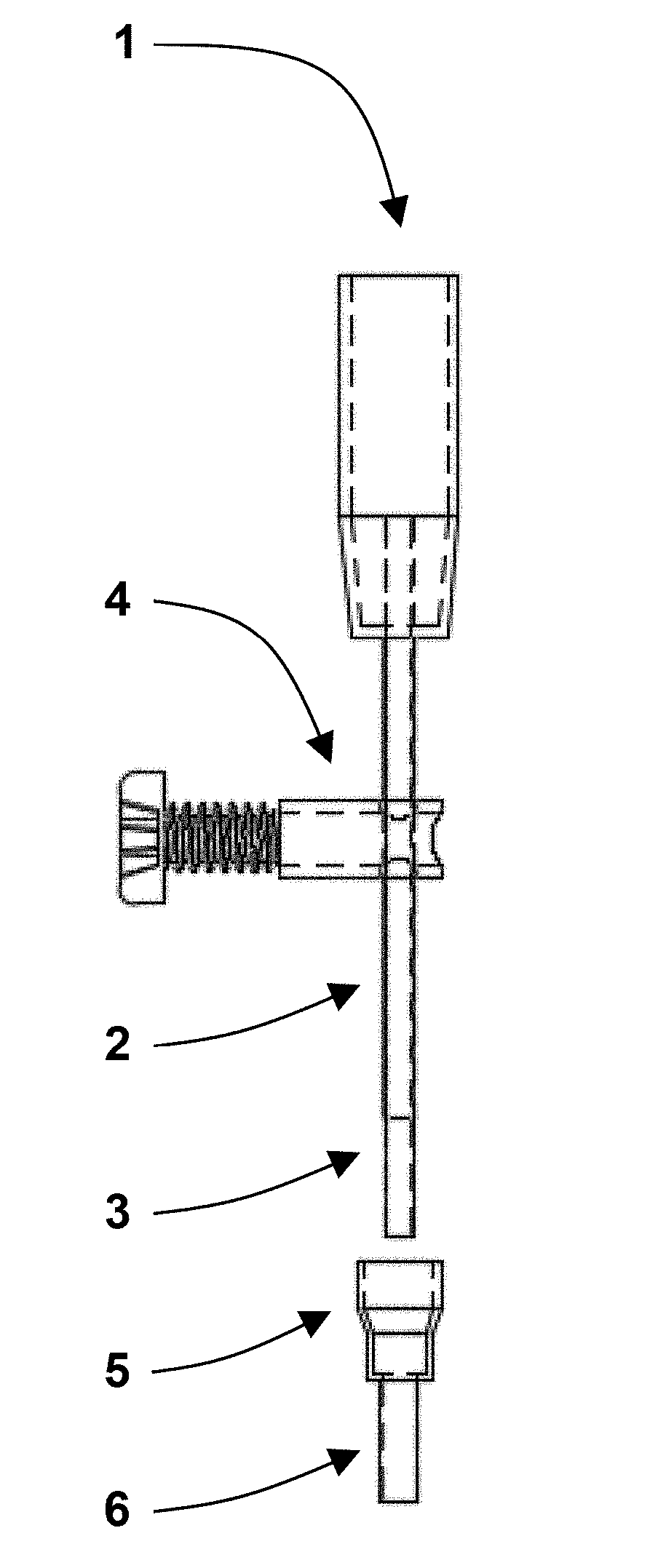
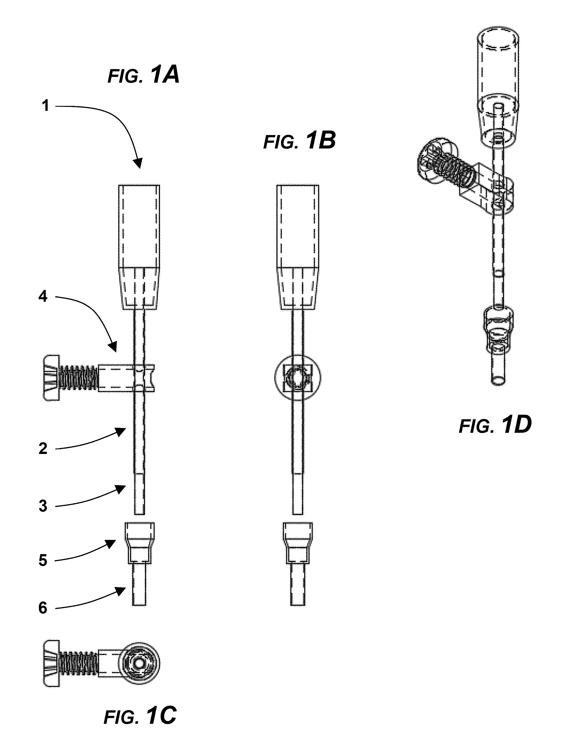
[0011] FIG. 1A is a simplified front view of an MRI-compatible mono-polar electrode in an exemplary embodiment, with internal structure shown in broken lines, and with the guide cannula and insulative sheath apart from the conductive tubing.
[0012] FIG. 1B is a side view of the MRI-compatible mono-polar electrode, taken along 1B-1B in FIG. 1A, with the guide cannula and insulative sheath apart from the conductive tubing.
[0013] FIG. 1C is an isolation top view of a stopper/set screw combination of the MRI-compatible mono-polar electrode, taken along 1C-1C in FIG. 1A.
[0014] FIG. 1D is a perspective view of the MRI-compatible mono-polar electrode, taken along 1B-1B in FIG. 1A, with the guide cannula and insulative sheath joined with conductive tubing.
[0015] FIG. 2A is a simplified view of the MRI compatible mono-polar electrode shown generally in FIG. 1, assembled with guide cannula and stopper/set-screw combination on.
[0016] FIG. 2B is a simplified view of the MRI compatible mono-polar electrode shown generally in FIG. 2B, unassembled with guide cannula and stopper/set-screw combination off.
[0017] FIG. 3A is a simplified perspective assembly view of a cranial bolt system for mounting to the skull and inserting the electrodes, showing multiple mono-polar probes in a treatment configuration.
[0018] FIG. 3B is a simplified top partial isolation view showing the insertion array of the electrode and taken generally along 3B-3B in FIG. 3A.
[0019] FIG. 3C is a partial isolation front view taken generally along 3C-3C in FIG. 3B, showing the cranial bolt with internal detail shown in broken lines. cranial bolts. C) Cranial bolt front view.
[0020] FIG. 3D is a isolation perspective view showing the cranial bolt of FIG. 3B.
[0021] FIG. 3E is a partial perspective view of the cranial bolt system shown in FIG. 3A, showing a single-port cranial bolt with ball mechanism to set/adjust insertion angle/trajectory.
[0022] FIG. 4A shows a partial perspective view of a full port probe tip, shown generally in FIG. 3A, in an embodiment.
[0023] FIG. 4B shows a partial perspective view of a step-down port probe tip, shown generally in FIG. 3A, in an embodiment.
[0024] FIG. 4C shows a partial perspective view of a fillet plug probe tip, shown generally in FIG. 3A, in an embodiment.
[0025] FIG. 4D shows a partial perspective view of a chamfer plug probe tip, shown generally in FIG. 3A, in an embodiment.
[0026] FIG. 4E shows a partial perspective view of a leaflet valve probe tip, shown generally in FIG. 3A, in an embodiment.
[0027] FIG. 4F shows a partial perspective view of an umbrella valve probe tip, shown generally in FIG. 3A, in an embodiment.
[0028] FIG. 5A is a schematic diagram showing an electroporation treatment in an exemplary embodiment, with two mono-polar probes inserted into brain tissue through guide cannulas.
[0029] FIG. 5B is a line graph showing waveforms and pulse parameters for Integrated Nanosecond Pulsed electroporation treatment method in an exemplary embodiment corresponding to FIG. 5A.
[0030] FIG. 6 is a schematic diagram of an electroporation treatment in an MRI suite, in an exemplary embodiment.
[0031] FIG. 7 is a collection of images from MRI compatibility testing for artifact/noise reduction in a method of electroporation, in an embodiment.
[0032] FIG. 8 is a functional diagram showing an electroporation system including a pulse generator, shielding port, MRI scanner, and electronic switch for separating cabling into multiple segments, in an exemplary embodiment.
[0033] FIG. 9A is an image of treatment on a potato using an Integrated Nanosecond Pulsed electroporation treatment method with a 2-5-2 .mu.s pulsing sequence, showing an MRI artifact left by nickel titanium electrodes disconnected from the generator before treatment.
[0034] FIG. 9B is an image of treatment on a potato using an Integrated Nanosecond Pulsed electroporation treatment method with a 2-5-2 .mu.s pulsing sequence, showing an MRI artifact left by nickel titanium electrodes connected to the pulse generator.
[0035] FIG. 9C is an image of treatment on a potato using an Integrated Nanosecond Pulsed electroporation treatment method with a 2-5-2 .mu.s pulsing sequence, showing the ablation zone of a 200-burst treatment, seen as the ovoid, contrast-enhancing area surrounding the nickel titanium electrodes.
[0036] FIG. 10 shows Method 100, which is illustrated by a flow chart of a protocol for electroporation treatment of tissue with simultaneous operation of an MRI scanner. The steps described herein represent those that would follow an initial surgery for placing a cranial bolt and cannula.
[0037] FIG. 11A is a Field Emission Scanning Electron Microscopy (FESEM) image of nitinol, in an exemplary embodiment.
[0038] FIG. 11B is a Field Emission Scanning Electron Microscopy (FESEM) image of nitinol, in an exemplary embodiment.
[0039] FIG. 11C is a Field Emission Scanning Electron Microscopy (FESEM) image of nitinol, in an exemplary embodiment.
[0040] FIG. 11D is a Field Emission Scanning Electron Microscopy (FESEM) image of nitinol, in an exemplary embodiment.
[0041] FIG. 11E is a Field Emission Scanning Electron Microscopy (FESEM) image of nitinol, in an exemplary embodiment.
DETAILED DESCRIPTION
[0042] Detailed embodiments of the present disclosure are herein. It may be understood that the disclosed embodiments are merely examples to illustrate aspects that may be embodied in various and alternative forms. Well-known materials or methods have been described in detail to avoid obscuring the present disclosure. Therefore, specific structural and functional details disclosed herein are not to be interpreted as limiting, but as a basis for the claims and for teaching one skilled in the art to variously employ the present disclosure.
[0043] This disclosure describes new devices and procedures to improve patient safety and treatment outcome for patients treated with electroporation therapy. The methods described are applicable for all ailments within the brain, head, neck, spinal cord or other specific locations within the body that may be treated with electroporation, including but not limited to tumors, essential tremors, and Parkinson's disease. The new procedures described apply to all waveforms capable of inducing electroporation, including reversible electroporation for drug delivery, irreversible electroporation (IRE) for tissue destruction, integrated nanosecond pulse irreversible electroporation, and sub-electroporation effects for blood-brain-barrier opening. The present disclosure reduces the risks and enhances treatments of patients receiving electroporation based procedures.
[0044] Referring to FIG. 1, which contains a set of engineering drawings of the MRI compatible mono-polar probe (i.e., electrode) (1) with accessories, including a guide cannula (5) and stopper/set-screw combination (4). The mono-polar probe consists of an insulative handle (1), adjustable insulative sheath (2) to control the location of electroporation, and conductive tubing (3) to deliver the electroporation pulses. The conductive tubing (3) extends into the center of the handle (1) to permit connection with electrical wiring (i.e., cable; not shown). The connection may be made with a removable, pressure fit connector, or joined permanently. The guide cannula (5) also contains an insulative sheath (6) through which the electrode is inserted. The guide cannula (5) or electrode (1) can also be utilized to deliver exogenous agents or place sensors for monitoring treatment. A) mono-polar probe (1) front view with guide cannula (5) and stopper/set-screw (4). B) Mono-polar probe side view. C) Mono-polar probe bottom view. D) Mono-polar projection.
[0045] FIG. 2 is a set of pictures of the fabricated MRI compatible mono-polar probe. A) Assembled with guide cannula (5) and stopper/set-screw (4) on. B) Unassembled with guide cannula (5) and stopper/set-screw (4) off.
[0046] FIG. 3 is a set of engineering drawings and a picture of a cranial bolt system (7) for mounting to the skull and inserting the electrodes. A) Assembly view showing multiple mono-polar probes (1) in a treatment configuration. B) Crain bolt top view with insertion array. C) Cranial bolt front view. D) Fabricated cranial bolt. E) Single-port cranial bolt with ball mechanism to set/adjust insertion angle/trajectory.
[0047] Referring to FIG. 4, which contains a set of engineering drawings for different probe tip configurations. Port or valved configurations are designed to permit the delivery of exogenous agents via fluid infusion (e.g., chemotherapy), fluid retrieval from the tissue (e.g., micro-dialysis), or measurement of tissue properties (e.g., electrical, thermal, mechanical) via the placement of sensors. A) Full-sized port from hollow conductive tubing (3). B) Step-down port using insulative insert. C) Fillet-plug using insulative insert. D) Chamfer-plug using insulative insert. E) Leaflet valve using insulative cap. F) Umbrella valve using insulative cap. An embodiment could also include a standalone cap without a valve or port mechanism.
[0048] Referring to FIG. 5, which is a schematic diagram of a typical electroporation treatment. A) Two mono-polar probes are inserted into brain tissue through guide cannulas (5). All tissue exposed to an electric field>500 V/cm is subject to electroporation. B) Typical waveform and pulse parameters for integrated nanosecond pulse irreversible electroporation treatment.
[0049] Referring to FIG. 6, which is a schematic diagram of an electroporation treatment in an MRI suite. The electrodes are attached to cables that travel through a shielded port to the pulse generator, which is houses in the control room. There are multiple points (8) along the length of the cabling where it may be disconnected/switched-open and separated into multiple segments. This improves safety by reducing the complexity of cabling during treatment preparation (e.g., patient transport) and reduces imaging artifacts/noise propagation when disconnected at different points.
[0050] Referring to FIG. 7, which is a collection of images from MRI compatibility testing for artifact/noise reduction. Each image shows two monopolar electrodes with different segments of cabling connected. Descriptions of each scenario are listed below the image.
[0051] Referring to FIG. 8, which is a functional diagram of the pulse generator, shielding port, and MRI scanner. A representation of an electronic switch is shown to indicate one possible method of separating the cabling into multiple segments. This could also be accomplished by electrical plugs, and the location can vary anywhere along the length of the cabling, including the electrode handle.
[0052] Referring to FIG. 9, which is a collection of images showing before and after images of treatments on potatoes using an integrated nanosecond pulse irreversible electroporation pulsing sequence (2-5-2 .mu.s). The MRI artifact left by the Nickel Titanium electrodes when they are (a) disconnected from the generator before treatment and (b) connected to the generator. (c) The ablation zone of the 200-burst treatment, seen as the ovoid, contrast-enhancing area surrounding the electrodes.
[0053] Referring to FIG. 10, Method 100 is described by a flow chart of an example protocol for treating tissue within an MRI scanner. An exemplary embodiment would include the surgical steps required to gain access to the brain via a craniectomy or burr hole. An elective pathway is provided to unplug the cables (mechanically or electrically) in between sets of pulses to reduce image artifacts/noise. Electrodes are placed in the tissue (9) based on the tumor geometry to ensure adequate coverage of the tumor with a threshold electric field. This could be accomplished with a stereotactic frame and/or infrared neuronavigation system, in which infrared tracking balls may be placed on the electrode handle directly, or as an attachment. Placing (9) may also include mounting a cannula (5) to a cranial bolt (7). The insertion depth is controlled by placing the stopper/set-screw (4) on the electrode shaft. The insertion depth and electrode position could also be controlled by operating a mechanical element. The electrode placement is validated with the infrared tracking system and/or medical imaging (10). This may occur simultaneously or sequentially (as shown) with electrode placement (9). If the placement is correct (11) a baseline image is collected (13) to establish pre-treatment contrast and/or temperature; if the placement is not correct the electrode placement is adjusted (12). The cables are connected to the electrodes (e.g., at the handle) (14), and baseline tissue properties are calculated (15). A low-voltage test pulse is applied (16) to ensure proper electric contact between the electrodes and the tissue, and to ensure that, if the voltage were scaled-up to the treatment level then, according to Ohm's law, the treatment protocol would fall within an acceptable generator current limit or safety limit (17). If the current is within an appropriate range, the voltage is increased to the treatment level and the treatment is applied (19). If the current is too low/high, the pulse parameters may be adjusted (18) and/or the electrodes may be re-positioned (12). Operating the pulse generator for applying the treatment involves entering the electrode spacing, calculating the applied voltage necessary to achieve a specific voltage-to-distance ratio, programming the pulse protocol (e.g., pulse duration, number, and repetition rate). The pulse generator could trigger the MRI scanner to acquire an image between pulses, or the MRI scanner could trigger the pulse generator to deliver pulses between image acquisitions. During treatment, there is the option to unplug the cables between pulses or groups of pulses (21), acquire an image (22), and re-plug the cables (23). There is also the option to leave the cables plugged-in and make measurements of tissue properties (20) or acquire images. Following treatment, the ablation is verified against some metric (24) and the procedure either ends (25) or starts over again for a new set of electrodes in a different portion of the tumor (1).
[0054] Referring to FIG. 11, which is a series of Field Emission Scanning Electron Microscopy (FESEM) images of nitinol. The first image (11A) is simply of nitinol under no pulse configurations and without insertion into Phosphate Buffer Solution (PBS, purchased from American BioInnovations, Sparks, Md., USA). Image 11B is of nitinol under no pulse configurations and inserted into PBS. All other images (11C-E) were pulsed at 90 pulses and 70 .mu.s with different voltages in PBS; image 11B with 1000V, 11C with 1500V, and image 11D with 2000V.
[0055] In embodiments, an Integrated Nanosecond Pulsed IRE system may provide more predictable ablations than systems providing longer waveforms and non-bipolar waveforms. In embodiments, short bi-polar waveforms provided by an Integrated Nanosecond Pulsed IRE system may provide ablations of improved predictability, such as by creating an electrically homogenous environment via capacitive coupling. Predictability may be of benefit in the ablation of portions of the brain with a predominance of white matter, which are anisotropic and have a higher conductivity along the long axis of the fibers versus perpendicular to the fibers. An exemplary list of advantages for Integrated Nanosecond Pulsed IRE systems, including reduced procedural time, reduced procedural complexity, and visualization of electroporation treatment in real-time under MRI guidance, is provided in Table 1. In embodiments, an Integrated Nanosecond Pulsed IRE system may be an H-FIRE.TM. Integrated Nanosecond Pulsed IRE system available from the present applicant (Voltmed Inc., Blacksburg, Va.).
TABLE-US-00001 TABLE 1 Clinical features, advantages, and direct patient benefits of using Integrated Nanosecond Pulsed IRE system TECHNICAL CLINICAL FEATURE ADVANTAGE BENEFIT Selective killing Ablation of cancer cells Decreases likelihood of cancer cells beyond tumor margin of tumor recurrence Non-thermal method Can treat tumors in Treatment of inoper- of cell death with proximity to major able tumors and fast electric fields vessels/nerves ablation recovery Non-thermal energy Faster than other Reduced procedure delivery completed treatment time and surgical in minutes complications Higher threshold for Does not require general Enables non-thermal electrically induced anesthesia or paralytics IRE in highly muscle stimulation sensitive areas or awake surgery More uniform electrical Penetrates through Generates more properties across differ- tissue/tumor predictable ablations ent tissue types and heterogeneities in tissue/tumor post-electroporation MRI-compatibility probe Provides physicians with Complete tumor for real-time feedback visualization of treatment coverage improves therapy success
[0056] The present disclosure provides improved Integrated Nanosecond Pulsed IRE treatment therapy. Embodiments may include a cannula-based electrode system. This may include monopolar MRI compatible electrodes. Such electrodes may be constructed with a rod approximately 10 cm long that is coated with a metal, such as copper, on one end so that the metal may be soldered to the wire connection. Alternatively, the metal may be uncoated and act itself as the "male" end to a paired "female" connector (e.g., banana jack). Nickel titanium may be used as the electrode material due to its small MRI artifact in a embodiment, but other metals, such as platinum, iridium, carbon and silicon can also be used. To visualize the electrode during placement, a ring or an insert composed of an MRI contrast material such as Gadolinium may be included near the tip of the electrode. In some embodiments, the ring may not exceed more than about 1 mm, which is similar to the resolution limit of MRI. This ring may be used as a bright landmark on MRI imaging to visualize when the probe has reached its target location, ensuring correct depth of insertion and correct spacing. In addition to Gadolinium, other material that enhance the contrast of MRI may be used such as manganese, iron oxide, and iron platinum. After the electrode rod is plated and soldered, or plugged-in to the wire, a handle, which has been custom designed using CAD software, is placed around the solder joint, or bare metal, and sealed using an autoclavable material such as the epoxy (Epoxy International, FDA-Bond 2) and a super glue, such as Loctite 4541, which are both autoclavable materials. Finally, a piece of insulation, such as MicroLumen, code 475-V.5, Lot#24178, code560-IV, Lot#41614; 8 cm is cut and a stopper, that can screw or lock into the skull or a preexisting skull mount is added to one end of the insulation and sealed with the same super glue. The MRI compatible electrodes may allow for the electrodes to be guided more precisely and the extent of electroporation to be directly observed by MR imaging. The treatment may then be monitored and changed as needed with MRI guidance.
[0057] For purposes of treating brain tumors, the probes to be used in the system may consist of monopolar or bipolar electrodes approximately 18-gauge, catheter electrodes, and a dispersive electrode (grounding pad), all MRI-compatible and single-use. The tip may be, as described in FIG. 4, open, port, valved, or plugged/capped. The number and arrangement of electrodes may vary. In one embodiment, no less than 2 (including single bipolar probe with an energized and ground surface), and no more than 6, probes may be active simultaneously and may be limited based on current and voltage capabilities. The probes may be identified by the system through RFID tagging to ensure disposal after first use in clinical settings.
[0058] The integrated nanosecond pulse irreversible electroporation system, in embodiments, may include a pulse generator, a monopolar probe, a bipolar probe, a catheter probe, and a dispersive electrode. The pulse generator may operate outside the sterile field and in some cases in an MRI control room (FIG. 6). The principal components of the generator (FIG. 8) consist of power electronics, a touchscreen display, and double foot switch pedal, all of which are housed in a wheeled cart. The end user may interact with the electronics through a graphical user interface on the touchscreen. Voltage, amperage, and impedance across active electrodes may be displayed throughout procedures. The generator may connect with a set of MRI-compatible probes through 6 high-voltage output connectors. The output parameters consist of high-frequency biphasic pulses with a maximum voltage and amperage of 5000 Volts and 100 Amps, respectively. In clinical settings, the output may be enabled by three possible triggers: signal from a double foot switch pedal operated by end user, signal from cardiac synchronization device, and signal from MRI unit to sync with image acquisition sequence. The output can also be disabled by either the foot switch or patient-triggered manual shut off. The generator may have analog and software safety components that may detect any system malfunctions including misconnections, over-currents, and over-voltages.
[0059] A method and system of electroporation may include MRI compatible materials. Such a system may include a guide cannula for precise location and placement of electrodes. Methods for electroporation may include connecting and disconnecting the cabling along its length at multiple points. An electroporation system may include different electrode tip embodiments for different functions (e.g., treatment only, fluid delivery, treatment monitoring).
[0060] An electroporation system may include a cannula-based electrode system, with a guide cannula for placing electrodes. This may allow for electrodes to be strategically placed to minimize distortion from heterogeneities or maximize ablation within the tissue. The guide cannula may be secured inside a cranial bolt with an array of guidance holes (FIG. 3A) that is mounted to the skull. An embodiment may include a cranial bolt designed for a single electrode with a tunable insertion angle (FIG. 3E). This may be accomplished through a ball and set-screw combination. The guide cannula may be imaged with MRI to ensure the proper trajectory before inserting the electrodes. The guide cannula may enable more accurate, precise placement of the electrodes in tissue and may provide more accurate treatment area.
[0061] The method for placing electrodes may strategically involve the use of medical imaging to make a numerical model of the treatment volume. This model may incorporate the tissue geometry via image acquisition and electrical properties of various tissue types or heterogeneities. Next, an optimization algorithm is developed for placing the electrodes, such that the predicted ablation volume resembles a theoretical solution for homogeneous tissue and/or is the largest obtainable ablation. For example, the target tissue may be exposed to an electric field>=500 V/cm (FIG. 5A). To improve imaging, low current may be applied to the tissue during image acquisition to counteract magnetic field heterogeneities and image artifacts caused by the presence of the electrode.
[0062] The cannula may be endowed with a variety of properties to improve its efficacy. The cannula may act as insulation. The cannula may be made of MRI compatible materials to allow for observed procedures. Useful materials for the cannula include polyimide, Teflon, or PEEK. Another embodiment includes mounting the cannula and/or electrode to a stereotactic frame without the use of a cranial bolt. Additionally, a robot arm may be used to place the cannula/electrode and electrode to tightly control insertion depth. This robot arm may be linked to an image acquisition system where the desired treatment zone may be drawn by the physician and visualized using contrast.
[0063] In embodiments, an integrated nanosecond pulse irreversible electroporation system may include a Pulse Generator System. Such a pulse generator system may be delivered through a custom-built integrated nanosecond pulse irreversible electroporation waveform generator (VoltMed Inc., Blacksburg, Va., USA) coupled with two (2) or more blunt-tip electrodes (O=1.2 mm; 200-104302; Angiodynamics, Inc. Queensbury, N.Y., USA). The electrodes may have an overall length of 15 cm, and may be connected to the pulse generator via 1.8 m insulated cables. The active exposure length of the electrode tips may be adjusted in 5 mm increments over a range of 40 mm.
[0064] The electrodes may be further improved in a variety of ways. Typically, in IRE procedures, non-shielded, insulative electrode leads are used. The disclosure described may add shielding to the electrode leads. This method may help reduce radiofrequency noise and image artifacts, which may permit more precise control of the ablation area. Additionally, electrodes may be improved by acting as both the ablation device and the physiologic sensor. Electrodes may be equipped for real-time measurement of tissue impedance using sensor electrode array placed along an insulative sheath. These modified electrodes may be used in combination for reversibly or irreversibly electroporating tissue and monitoring electrical activity. The electrophysiological data gathered by the monitoring electrodes may be incorporated in treatment planning for electroporation procedures.
[0065] In IRE procedures, an important adverse effect of treatment is thermal damage. The disclosure may minimize unwanted thermal damage by directly observing the temperature increase as a result of treatment. This is done by using a temperature probe on the electrode. With active observation of the temperature, pulse duration and/or duty cycle may be adjusted during treatment to prevent temperatures lethal to cells from being reached. Additionally, the disclosure can utilize a method for performing MRI thermometry and adjusting the pulse duration and/or duty cycle to prevent lethal temperatures from being reached.
[0066] Another adverse effect commonly encountered in electroporation therapy is the interaction of the pulses with critical structures. The present disclosure utilizes a method of directing current away from critical structures, such as ventricles. This involves placing insulative material along the electrode that is positioned between the conductive surface and the structure to be spared. An external grounding pad or array of electrodes may be used to direct the current away from the critical structure. The ventricle or cerebral spinal fluid surrounding the brain can also be used as a "fluid electrode" by inserting a conductive probe into those regions. This allows for larger treatment volumes and more diffuse regions of electroporation. A grounding pad may be used in combination with needle electrodes in this system and may be modified in a variety of ways in improve outcome. The needle electrodes and grounding pad may be used so that the bulk tissue electrical resistances local to the electrodes and grounding pad are modified to maximize the area of treatment. Additionally, all electrodes involved in the ablation area may be cooled down prior to insertion to minimize increases in tissue conductivity near needle-electrodes. A fluid of low conductivity may be delivered in the vicinity of the needle-electrode to prevent increases in electric field magnitude near the dispersive electrode. This may result in larger ablations near the needle-electrode and minimizing muscle stimulation.
[0067] Neuronal networks can also be adversely affected by treatment in the brain. The disclosure provides a method for controlling pulse timing to minimize effect on neuronal networks. This method consists of using a train of high-frequency, biphasic pulses, in which the phase delay between pulses of alternating polarity is controlled to minimize or maximize nerve desynchronization. This could also involve purposely administering electrical stimulation to create a latency period in neuronal activity, during which electroporation pulses are administered. The method may be improved by synchronizing the delivery of electroporation pulses before, during, or after the recording of inherent or evoked electric potentials.
[0068] It is understood that the electrodes could be expanded or reduced in both length and circumference to allow for larger ablation zones within other areas of the body. The conductive material used for electrodes may be a semi-conductive material. This semiconductor may be, but is not limited to, carbon or silicon-based materials.
[0069] An autoclavable material such as Loctite 4541 and Epoxy International, FDA-Bond 2, are used for the construction of the probes in an embodiment because they are both autoclavable materials as well as are FDA approved. However, other FDA approved autoclavable materials may also be used. The electrode may be made of a metal that has small MRI artifacts, such as nickel titanium. The pulse parameters for integrated nanosecond pulse irreversible electroporation (FIG. 5B) are different from other IRE pulses. They are shorter and bipolar, which is essential for creating a uniform current distribution, preventing electrically-induced muscle contractions, and limiting electrochemical effects. The exposed, non-insulated portion of the electrode controls where the therapy is delivered. No therapy would be delivered if the guide cannula were longer, or the same length as, the electrodes. Another embodiment includes an adjustable length cannula or region of electrode insulation, such that the extent of treatment may be modified, or the electrode may be covered following treatment but before retraction.
[0070] The system described can utilize switching mechanisms, as seen in FIGS. 6 and 8, that may be in the MRI room near the feed through to the control room, and near the elegy rode handle, directly before the electrodes themselves. This switching mechanism may be a physical disconnect or an electrical disconnect. The electrical disconnect could include but is not limited to a physical switch, relay switch, and or software switch. The electrical or physical switching mechanism may be controlled by human or robotic systems. Disconnecting the cabling near the electrode handle reduces noise and image artifacts (FIG. 7).
[0071] According to the present disclosure, embodiments may combine MRI compatible electrodes to administer the therapy, shielding the electrode leads to prevent emanating radiofrequency noise or control the direction of treatment, disconnecting the cabling at specified locations to limit noise and image artifacts, placing electrodes strategically within a guide cannula to minimize distortion from heterogeneities or maximize ablation within the tissue, utilizing conductive fluids, innate or external, such as cerebral spinal fluid or grounding pads to provide a pathway for current return, utilizing different electrode tips for treatment, monitoring, and fluid infusion, and for timing of the electrical waveforms with inherent brain electrical activity is to enhance safety and treatment outcomes for patients undergoing electroporation procedures.
[0072] The utility of the system and method disclosed herein has been established by studies. The following examples are meant only to be illustrative and are not meant as limitations on the scope of the invention or of the appended claims.
[0073] The applicant conducted both theoretical and experimental studies characterizing the effects of IRE for soft tissue ablation in the brain in a pilot safety and efficacy study on six normal dogs. The results showed that the treatment was well-tolerated and spared major brain vasculature, suggesting that IRE is suitable for treatment of tumors adjacent to, or enveloping, critical vascular structures. Seven (7) canine patients with aggressive gliomas were successfully treated without causing collateral damage to the surrounding normal brain using IRE.
[0074] Post-IRE magnetic resonance imaging (MRI), histopathology, and clinical neurological examinations indicated that tumor reduction was achieved in six (6) of the seven (7) canines. The median 14-day post-IRE Karnofsky Performance Score (KPS) of the 6/7 dogs surviving to discharge was 80 (range 60-90), and was improved over pre-treatment values in all cases. Objective tumor responses were seen on MRI in 4/5 of dogs with quantifiable target lesions. Two dogs experienced survivals in excess of one year, including 1 dog that demonstrated a complete response to IRE treatment for 4+ years to date. With other therapies, median survivals of 0.2, 0.9, and 4.9 months have been reported for dogs with brain tumors receiving either symptomatic therapy, cytoreductive surgery, or multimodal therapy (surgery and radiotherapy or hyperthermia), respectively, illustrating the poor prognosis.
[0075] A technical challenge at the time was the strong muscle contractions induced by IRE pulses. This required the use of enhanced anesthetic protocols that included neuroparalytic agents. Even then, pulse induced movement was still present and shown to disrupt electrode-tissue contact. Dislodging of the electrodes poses a risk for the more than 50% of patients with brain tumors in poor surgical locations (e.g., corpus callosum, motor cortex, insula, multiple locations, etc.). Additionally, muscle paralysis involves general anesthesia and mechanical ventilation, which precludes the use of IRE in `awake` neurosurgical interventions or in severely debilitated patients.
[0076] A prospective, single center, pilot study of canine patients was designed according to IDEAL stages 1/2a of surgical innovation to evaluate the feasibility and safety of ablating brain tumors with. Client-owned dogs with naturally occurring intracranial meningiomas were recruited through the treatment center's referral network and by registry of the trial on a national veterinary clinical trials database. To be eligible for the trial, dogs had to have clinical signs of brain disease, a diagnostic brain magnetic resonance imaging (MRI) scan demonstrating a solitary mass lesion>1 cm in diameter with imaging characteristics compatible with a meningioma, Karnofsky Performance Score (KPS).gtoreq.60, and be free of significant concurrent cardiopulmonary, renal, and hepatic disease, or other malignancy. When applicable, dogs with structural epilepsy had to have seizures that were controlled on anticonvulsant medications. Exclusion criteria included the receipt of any type of prior brain radiotherapy, or treatment with a cytotoxic chemotherapy drug within 6 weeks of trial enrollment. Owners provided written, informed consent to enroll their dogs into the study.
[0077] Testing of the MRI compatible probes were conducted and shown in FIG. 7. The artifact, as seen from these images, shows it being only 5 mm from a 1 mm diameter probe. Each image also shows how the image is affected by the connection of the electrode to each specific connection point as illustrated in FIG. 6. Also imaged was the guide cannula alone in the copper sulfate (CuSO4) solution, which may be seen in FIG. 7 as the image on the bottom row and furthest on the right. The series of images were taken with a spin echo with the following specifications: TR--500.0 ms, TE--2.7 ms, and BW-- 930.0 Hz. The images were imaged with the use of a 1.5 MRI scanner (Phillips Medical Systems, Winston-Salem, N.C., USA).
[0078] FESEM was used to image nitinol (purchased from VascoTube GmbH, Baden-Wuerttemberg, Germany) and are shown in FIG. 11. Imaging was done at the ICTAS Nanoscale Characterization and Fabrication Laboratory (Blacksburg, Va., USA) using their LEO 1550 (Zeiss, Dublin, Calif., USA) which is capable of resolution in the 2-5 nm size range. For all of the imaging, we used the SE2 detector for general purpose imaging and at an Electron High Tension (EHT) value of 5 kilovolts; EHT is the voltage through which the electrons are accelerated toward the sample. The magnitude of all the samples was 200.times.. Immersion testing was done using PBS due to the similar pH, osmolarity, and ion concentrations as that of the human body. The samples were pulsed using a BTX T820 pulse generator (Holliston, Mass., USA) and, using gloves to avoid contamination, mounted onto aluminum stubs, which were fixed onto the ZEISS specimen holder using carbon tape.
[0079] As seen from the images, there is no apparent difference in surface condition due to pulsing and varying voltages. The crystal structures seen in FIG. 11B are likely NaCl from the PBS. We know this because the crystal structures are absent in FIG. 11A, where nitinol was not immersed in PBS. It appears the presence of cracks and contamination on the surface stays relatively constant; those in FIGS. 11D and 11E are due to cutting of the nitinol wire at those points.
[0080] Potatoes were treated with a variety of pulse sequences along with different burst amounts to show the ablation sizes that could be achieved. Each potato was imaged before treatment and after treatment. In FIG. 9, the ablation this testing may be seen with the 2-5-2 pulse (.mu.s) sequence and both the 40-burst along with the 200-burst amount and the ablation sizes of each. Each post image was taken almost directly after the treatment. All images were taken by a 1.5 MRI scanner (Phillips Medical Systems, Winston-Salem, N.C., USA), imaging with a flair dorsal with a TE of 3.4 ms. There is an optimized scan for the 1.5 MRI scanner called a UTE (ultrashort echo time) where the TE is lowered to 0.05 ms and this scan can reduce the artifact of the electrodes to just 2.6 mm.
[0081] A prospective, single center, pilot study of canine patients was designed according to IDEAL stages 1/2a of surgical innovation to evaluate the feasibility and safety of ablating brain tumors with. Client-owned dogs with naturally occurring intracranial meningiomas were recruited through the treatment center's referral network and by registry of the trial on a national veterinary clinical trials database. To be eligible for the trial, dogs had to have clinical signs of brain disease, a diagnostic brain magnetic resonance imaging (MRI) scan demonstrating a solitary mass lesion>1 cm in diameter with imaging characteristics compatible with a meningioma, Karnofsky Performance Score (KPS).gtoreq.60, and be free of significant concurrent cardiopulmonary, renal, and hepatic disease, or other malignancy. When applicable, dogs with structural epilepsy had to have seizures that were controlled on anticonvulsant medications. Exclusion criteria included the receipt of any type of prior brain radiotherapy, or treatment with a cytotoxic chemotherapy drug within 6 weeks of trial enrollment. Owners provided written, informed consent to enroll their dogs into the study.
[0082] On the day of admission (Day 1), dogs underwent pre-treatment KPS scoring, and complete physical, neurological, and laboratory examinations. They were anesthetized using a complete intravenous protocol consisting of premedication with methadone and midazolam, induction with propofol, and maintenance with propofol and remifentanil constant rate infusions. Anesthetized dogs were instrumented in an MRI compatible, small animal stereotactic headframe (Dynatech, Dynatech Machining, Union City, Calif., USA). MRI images of the brain were obtained for therapeutic planning (see Supplementary Digital Content 1--Methods, MRI Protocol) as previously reported. Parasagittal meningiomas were classified using the Sandor schema after acquisition of MRI venograms (very). After stereotactic images were obtained, dogs were recovered from anesthesia.
[0083] Patient-specific integrated nanosecond pulse irreversible electroporation treatment plans were developed using MRI-based tissue segmentation, volumetric meshing, and finite element modeling according to previously described methods (see Supplementary Digital Content 1--Methods, Treatment Planning). The therapeutic planning procedure was customizable and generated three-dimensional patient and tumor specific outputs. These outputs depicted the expected electric field distribution and Joule heating given the electrode approach and configuration for each electrode pair being used in the treatment.
[0084] On Day 2, dogs were placed under general anesthesia, instrumented in the stereotactic headframe, and aseptically prepared for surgery. To monitor for muscle contractions, a 3-axis accelerometer breakout board (ADXL335, Adafruit Industries, New York, N.Y., USA) with a sensing range of .+-.3 g was sutured to the skin of each dog in the dorsal cervical region at the level of the C2 vertebra. In the operating theater, each dog underwent a craniectomy approach of sufficient size to expose the tumor for integrated nanosecond pulse irreversible electroporation system treatment and subsequent tumor resection. Following completion of the tumor exposure, incisional biopsies of the tumor were obtained. Integrated nanosecond pulse irreversible electroporation system treatments were delivered stereotactically according to pretreatment plans by mounting and advancing the electrodes to the target region using micromanipulator arms of the headframe. Pulse delivery was synchronized with the electrocardiogram (Ivy Cardiac Trigger Monitor 3000, Branford, Conn., USA) to prevent cardiac arrhythmias. The electrodes were removed from the brain, and each patient underwent tumor resection using standard techniques. Following resection, surgical wounds were closed routinely, and then immediate post-treatment brain MRI examinations performed. All dogs received perioperative antibiotics (cefazolin, 22 mg/kg, IV, q 8 hours) and buprenorphine (0.003 mg/kg, IV or SC, q 6-8 hours) for at least 24 hours following recovery from the high-frequency irreversible electroporation treatment. Following anesthetic recovery on Day 2, and on each subsequent day of hospitalization until discharge, each dog underwent post-treatment KPS scoring, complete physical, neurological, and laboratory examinations, and adverse event (AE) monitoring. The study ended after each dog completed a 14-day post-treatment recheck clinical examination, KPS score, and AE assessment.
[0085] The primary end-point was to evaluate the safety of integrated nanosecond pulse irreversible electroporation system for the treatment of brain tumors. To this study, safety was defined as the absence of severe clinical toxicity within 14 days of the integrated nanosecond pulse irreversible electroporation system. Severe toxicity was clinically defined by a .gtoreq.20-point decline in the KPS from pre-treatment values, or development of grades 3, 4, or 5 AE, as classified according to the Cancer Therapy Evaluation Program's Common Terminology Criteria for Adverse Events (NCI CTCAE v4.0).
[0086] Secondary end points included direct neurotoxicity evaluations determined from post-treatment imaging studies and morphologic evaluation of tumor ablations. Following resection, each tumor was immersion fixed in bloc in 10% neutral buffered formalin for 48 hours. After fixation, the tumor was mounted in matrix slicer (Zevi Instruments, Pittsburgh, Pa., USA), photographed, and then serially sectioned in the transverse plane at 2 mm intervals. Sections were stained routinely with hematoxylin and eosin (H&E, Sakura Fintech, Torrance, Calif., USA). Light microscopy was used to type and grade tumors according to World Health Organization criteria, and to perform qualitative morphometric analyses. Ablation volumes were obtained using commercial image analysis software with Cavalieri estimator (Stereo Investigator, MBF Biosciences, Williston, Vt., USA).
[0087] Three dogs with intracranial meningiomas enrolled in and completed the study between March and July 2016. No evidence of muscle or nerve excitation or cardiac arrhythmia during any pulse delivery was observed in any dog. Additionally, no displacement was detected by the accelerometers for any of the delivered pulses, nor were any significant post-treatment laboratory abnormalities attributable to integrated nanosecond pulse irreversible electroporation system detected in any dog.
[0088] No intra- or post-operative AE were observed in Dogs 1 and 3, and these dogs were discharged from the hospital with static clinical examinations 24 hours after the integrated nanosecond pulse irreversible electroporation system procedure. Intraoperatively, Dog 2 experienced intracranial hemorrhage and subsequent hypotension following disruption of a collateral vein during tumor resection. Hemorrhage was controlled with topical hemostatic agents, temporary venous hemoclipping, and blood patches. Post-operatively, Dog 2 developed a depressed level of consciousness, an exacerbation of pre-existing hemiparesis, and 10-point post-operative decline in KPS score from baseline. Due to intraoperative AE, immediate post-operative imaging was not performed in Dog 2. The hypotension resolved upon anesthetic recovery. Dog 2 was discharged from the hospital 7 days after the procedure, and its neurological status returned to pre-treatment value by the day-14 recheck.
[0089] No imaging evidence of direct neurotoxicity or collateral damage to brain tissues outside of H-FIRE treatment zones was observed in Dogs 1 and 3 on immediate post-treatment MR examinations, or in Dogs 1 and 2 six months after treatment. In Dogs 1 and 2, ablations completely disrupted the cytoarchitecture of the tumors, resulting in homogeneous regions of tumor necrosis clearly delineated from adjacent untreated areas. In Dog 3, ablations resulted in non-uniform treatment regions characterized by patchy necrosis and, in areas surrounding psammoma bodies, a marked neutrophilic and lymphocytic infiltrate surrounding islands of edematous but viable tumor cells.
[0090] Dogs were followed off-protocol for six months or until death. No dog received other treatment in the six months following integrated nanosecond pulse irreversible electroporation system ablation. Dog 1 was alive, seizure free, and had no evidence of tumor six months after treatment. Dog 2 was alive six months post-treatment, but required escalation of anticonvulsant therapy for persistent post-treatment seizure activity, and had suspected residual or recurrent tumor identified on MRI examination performed 5 months after treatment. Dog 3 died 76 days after treatment due to complications arising from recurrent status epilepticus.
[0091] An integrated nanosecond pulse irreversible electroporation system and method as disclosed herein provides an ablative technique for the treatment of spontaneous brain tumors. An integrated nanosecond pulse irreversible electroporation system and method as herein disclosed is capable of safely ablating defined focal areas of normal canine and rodent brains as well as spontaneous glioma.
[0092] The blood-brain-barrier (BBB) presents a significant obstacle to the delivery of systemically administered drugs for the treatment of brain cancer and neurological disorders, such as Parkinson's disease and essential tremor. According to the present disclosure, two distinct pulse regimes may induce a defined zone of BBB disruption. When ablation protocols are implemented (1000 V/cm, 90 pulses) a reversible penumbra of BBB disruption may exist outside the zones of complete cell death and preferential cancer cell death. Additionally, sub-lethal protocols have been defined that may utilize a lower applied electric field (250 V/cm) and greater number of pulses (300 pulses). An electric field based system for BBB disruption could represent a clinically useful platform.
[0093] Reversible electroporation with a device as herein disclosed may be used to deliver drugs into cells within the treatment area. Irreversible electroporation as disclosed may be used to kill a specific type of cells within the treatment area. Both may be used together with different ablation zones consisting of each reversible, outer edge, and irreversible electroporation, center of the ablation.
[0094] The apparatus and methods described herein may provide treatments for neurological disorders. Such disorders may include, for example, brain tumors, essential tumors, and Parkinson's disease. The methods may include pulse waveforms capable of inducing irreversible electroporation for tumor ablation (with and without accompanying thermal effects), reversible electroporation for drug delivery, and sub-electroporation effects for blood-brain-barrier opening (e.g., modulation of tight junctions). Methods as disclosed for controlling pulse timing to minimize effects on neuronal networks may use a train of high-frequency, biphasic pulses, in which the phase delay between pulses of alternating polarity is controlled to minimize or maximize nerve desynchronization. In embodiments, the positive phase may be of higher amplitude and shorter duration than the negative phase, such that the overall waveform is charged balanced. In some embodiments, the phases may be of equal duration and amplitude. In embodiments, electrical stimulation may create a latency period in neuronal activity, during which electroporation pulses are administered. In some embodiments, the delivery of electroporation pulses may be synchronized before, during or after the recording of inherent or evoked electric potentials.
[0095] The apparatus and method described herein are ways of directing current away from critical structures, such as the ventricles. Place insulative material along the electrode that is positioned between the conductive surface and the structure to be spared. Use an external grounding pad or array of electrodes to direct current away from the critical structure. Treatment electrodes may be placed in the tissue. The side of the treatment electrode facing the ventricle may be insulated. An external electrode array placed in contact with the subject is further used to direct current away from the ventricle. In embodiments, the ventricle or cerebral spinal fluid surrounding the brain can also be used as a "fluid electrode" by inserting a conductive probe into those regions. This may help create larger treatment volumes or more diffuse regions of electroporation.
[0096] Systems and methods described herein may enable placing electrodes strategically to minimize distortion from heterogeneities or maximize ablation. Systems and methods described herein may use medical imaging to make a numerical model of the treatment volume that incorporates the electric properties of various tissue types or heterogeneities. Systems and methods described herein may include an optimization algorithm for placing the electrodes, such that the predicted ablation volume may resemble a theoretical solution for homogeneous tissue and/or is the largest obtainable.
[0097] Systems and methods described herein may use a previously implanted deep brain stimulation (DBS) electrode to administer electroporation. Beneficial effects of DBS may become suppressed over time, in which case an ablative or drug delivery method may be utilized to treat the tissue.
[0098] The apparatus and method described herein for inserting an electrode through a guide cannula may include a cannula which may be mounted to skull following creation of burr hole. In some embodiments, the cannula may act as insulation. In some embodiments, the electrode and cannula may be made from MRI compatible materials. In some embodiments, the electrode spacing may be designed to minimize MRI artifacts. In some embodiments, a low current may be applied to tissue during image acquisition to counteract magnetic field heterogeneities and image artifacts caused by the presence of the electrodes. In some embodiments, a robot arm may control insertion depth of cannula and electrode. In some embodiments, a contrast agent may be used to distinguish treatment zone from other tissue. In some embodiments, a drawing of a desired treatment zone may be prepared.
[0099] Systems and methods described herein may shield the electrode leads for compatibility with operation of MRI equipment. The shielding may extend, for example, the full length of leads to the exposed, energized and grounded electrodes. Shielding may reduce radiofrequency noise and leakage of current into the tissue outside the treatment site.
[0100] Systems and methods described herein may perform MRI thermometry and adjusting the pulse duration and/or duty cycle to prevent lethal temperatures from being reached. Systems and methods described herein may use a temperature probe on the electrode and may include adjusting the pulse duration and/or duty cycle to prevent lethal temperatures from being reached. Systems and methods described herein may include increased electrode diameter and may compress surrounding tissue. In embodiments, systems and methods described herein may apply all of the techniques above in combination with an adjuvant Chemotherapy, Radiosensitizer, Peptide, or drug Immunostimulatory agent.
[0101] The terms and expressions that have been employed are used as terms of description and not of limitation, and there is no intention in the use of such terms and expressions of excluding any equivalents of the features shown and described or portions thereof, but it is recognized that various modifications are possible within the scope of the invention claimed. Thus, it may be understood that although the present disclosure has been specifically disclosed by embodiments and optional features, modification and variation of the concepts, herein disclosed, may be resorted to by those skilled in the art, and that such modifications and variations are considered to be within the scope of this.
[0102] It is understood that embodiments may apply to performing a combination of electroporation and thermal ablation/damage, such that if the pulse duration or number is increased to allow heating near the electrodes.
[0103] Embodiments are within the scope of the disclosure and the following claims. In general, the terms and phrases used herein have their art-recognized meaning, which may be found by reference to standard texts, journal references and contexts known to those skilled in the art. The preceding definitions are provided to clarify their specific use in the context of the invention. All references cited herein are hereby incorporated by reference to the extent that there is no inconsistency with the disclosure of this specification. Insofar as the description above and the accompanying drawings disclose any additional subject matter that is not within the scope of the claims, the inventions are not dedicated to the public and the right to file one or more applications to claim such additional inventions is reserved.
* * * * *
D00000
D00001
D00002
D00003
D00004
D00005
D00006
D00007
D00008
D00009
D00010
D00011
XML
uspto.report is an independent third-party trademark research tool that is not affiliated, endorsed, or sponsored by the United States Patent and Trademark Office (USPTO) or any other governmental organization. The information provided by uspto.report is based on publicly available data at the time of writing and is intended for informational purposes only.
While we strive to provide accurate and up-to-date information, we do not guarantee the accuracy, completeness, reliability, or suitability of the information displayed on this site. The use of this site is at your own risk. Any reliance you place on such information is therefore strictly at your own risk.
All official trademark data, including owner information, should be verified by visiting the official USPTO website at www.uspto.gov. This site is not intended to replace professional legal advice and should not be used as a substitute for consulting with a legal professional who is knowledgeable about trademark law.