Filling Structure For A Graft System And Methods Of Use
Rao; K.T. Venkateswara ; et al.
U.S. patent application number 16/382118 was filed with the patent office on 2019-08-01 for filling structure for a graft system and methods of use. The applicant listed for this patent is Endologix, Inc.. Invention is credited to Raj P. Ganpath, Anupama Karwa, Amy Lee, K.T. Venkateswara Rao.
| Application Number | 20190231515 16/382118 |
| Document ID | / |
| Family ID | 44226769 |
| Filed Date | 2019-08-01 |


| United States Patent Application | 20190231515 |
| Kind Code | A1 |
| Rao; K.T. Venkateswara ; et al. | August 1, 2019 |
FILLING STRUCTURE FOR A GRAFT SYSTEM AND METHODS OF USE
Abstract
A system for treating an aneurysm includes a first double-walled filling structure having an outer wall and an inner wall. The filling structure is adapted to be filled with a hardenable fluid filling medium so that the outer wall conforms to an inside surface of the aneurysm and the inner wall forms a generally tubular lumen to permit blood flow therethrough. The inner wall comprises a blood contacting layer and a reinforcing layer. The reinforcing layer prevents circumferential creep or elastic expansion of the lumen.
| Inventors: | Rao; K.T. Venkateswara; (San Jose, CA) ; Ganpath; Raj P.; (Mountain View, CA) ; Lee; Amy; (Sunnyvale, CA) ; Karwa; Anupama; (San Francisco, CA) | ||||||||||
| Applicant: |
|
||||||||||
|---|---|---|---|---|---|---|---|---|---|---|---|
| Family ID: | 44226769 | ||||||||||
| Appl. No.: | 16/382118 | ||||||||||
| Filed: | April 11, 2019 |
Related U.S. Patent Documents
| Application Number | Filing Date | Patent Number | ||
|---|---|---|---|---|
| 12966852 | Dec 13, 2010 | |||
| 16382118 | ||||
| 61291279 | Dec 30, 2009 | |||
| Current U.S. Class: | 1/1 |
| Current CPC Class: | A61F 2230/0008 20130101; A61F 2/90 20130101; A61F 2/07 20130101; A61F 2002/075 20130101; A61F 2002/077 20130101; A61F 2230/0067 20130101 |
| International Class: | A61F 2/07 20060101 A61F002/07 |
Claims
1.-24. (canceled)
25. A system for treating an aneurysm in a patient, said system comprising: a double-walled filling structure having an outer wall and an inner wall, wherein the filling structure is adapted to be filled with a hardenable fluid filling medium such that when said filling structure is positioned across the aneurysm and filled with said hardenable fluid filling medium, said outer wall expands to conform to an inside surface of the aneurysm and said inner wall forms a tubular lumen to permit blood flow therethrough; and a reinforcing tube disposed over said inner wall, wherein said reinforcing tube is separate from said inner wall and is adapted to prevent circumferential creep or elastic expansion of said tubular lumen after deployment.
26. The system of claim 25, wherein said reinforcing tube comprises a metal, textile, membrane, or polymer mesh that surrounds a blood contacting layer defined by said inner wall so as to avoid contact with blood flowing through the tubular lumen formed by said inner wall.
27. The system of claim 25, wherein said reinforcing tube comprises fibers or filaments disposed around said tubular lumen formed by said inner wall and oriented circumferentially so as to increase resistance to radial expansion.
28. The system of claim 25, wherein said reinforcing tube comprises fibers or filaments disposed spirally around the tubular lumen formed by said inner wall and adapted to resist radial expansion of the inner wall of the lumen.
29. The system of claim 27, wherein the fibers or filaments comprise a metal, a polymer, a membrane, or a textile.
30. The system of claim 25, wherein the tubular lumen formed by said inner wall has an inner wall longitudinal length, and wherein said reinforcing tube has a reinforcing tube longitudinal length that is less than said inner wall longitudinal length.
31. The system of claim 25, wherein said filling structure is configured so that the tubular lumen formed by said inner wall has proximal and distal ends, and wherein the proximal and distal ends are flared.
32. The system of claim 25, wherein said inner wall is conformable to a shape and diameter of an expanded endoframe as limited by the diameter of the reinforcing tube during filling; and wherein said reinforcing tube is attached to the inner wall.
33. The system of claim 25, wherein said reinforcing tube is separate from said inner wall so that said reinforcing tube is movable relative said inner wall before and/or during deployment across the aneurysm.
34. The system of claim 25, wherein said separate reinforcing tube is attached to the inner wall by one or more sutures.
35. The system of claim 25, wherein said reinforcing tube is positioned between said inner wall and said outer wall.
36. The system of claim 25, wherein said reinforcing tube occupies a space between said inner wall and said outer wall.
37. The system of claim 25, wherein said reinforcing tube is made of a material having anisotropic stress properties oriented such that its greatest tensile strength is circumferential.
38. The system of claim 25, wherein a material of which the reinforcing tube is formed surrounds the inner layer wall and is contiguous along a length of the reinforcing tube.
39. The system of claim 25, wherein a material of which the reinforcing tube is formed surrounds the inner layer wall with an uninterrupted continuous circumferential horizontal cross-section of the filling structure.
40. A method for treating an aneurysm in a patient, said method comprising: providing an expandable endoframe and a double-walled filling structure having an outer wall and an inner wall, wherein said expandable endoframe and said double-walled filling structure are separate components; positioning said double-walled filling structure across the aneurysm; positioning said expandable endoframe across the aneurysm and expanding said expandable endoframe to an expanded configuration; filling said double-walled filling structure with a hardenable fluid filling medium so that said outer wall conforms to an inside surface of the aneurysm and said inner wall forms a generally tubular lumen therethrough across the aneurysm to permit blood flow therethrough, wherein said inner wall is conformable to the shape and diameter of the expanded endoframe during filling; and constraining said inner wall forming said generally tubular lumen from radial expansion of the inner wall with a separate reinforcing tube surrounding said inner wall forming said generally tubular lumen, said separate reinforcing tube being disposed between the outer wall and the inner wall, wherein the reinforcing tube is adapted to prevent circumferential creep or elastic expansion of said tubular lumen after deployment.
41. The method of claim 40, wherein said reinforcing tube has a reinforcing tube longitudinal length less than an inner wall longitudinal length and is disposed around said inner wall forming said tubular lumen along a portion of the inner wall.
42. The method of claim 40, wherein filling comprises filling a space between said inner wall and said outer wall such that a first space between said inner wall and said reinforcing tube and a second space between said reinforcing tube and said outer wall is filled with said hardenable curing medium.
43. The method of claim 40, wherein providing said double-walled filling structure includes said separate reinforcing tube which has been positioned about said inner wall during assembly of said double-walled filling structure such that said reinforcing tube is movable relative to said inner wall before and/or during deployment.
44. A system for treating an aneurysm in a patient, said system comprising: an expandable endoframe positionable across the aneurysm; a first double-walled filling structure having a differential functional construct including a toroidal outer surface having a tubular inner lumen formed therethrough, wherein said expandable endoframe and said first double-walled filling structure are separate components, wherein said filling structure defines a fillable space fillable with a hardenable fluid filling medium such that when said filling structure is positioned across the aneurysm around said expanded endoframe and filled with said hardenable fluid filling medium, an outward facing wall surface conforms to an inside surface of the aneurysm and an inward facing wall surface forms said tubular inner lumen therethrough, wherein when expanded said expandable endoframe supports said inward facing wall forming said tubular lumen to permit blood flow therethrough, and a reinforcing sleeve that is separate from said inward facing wall and is disposed within said fillable space and attached to the inward facing wall such that said reinforcing sleeve inhibits radial expansion of said inward facing wall forming said tubular lumen from expansion of said endoframe and due to creep or elastic expansion of said inward facing wall by outwardly directed mechanical forces from blood flow and long-term aneurysmal remodeling.
Description
CROSS-REFERENCES TO RELATED APPLICATIONS
[0001] The present application is a non-provisional of, and claims the benefit of U.S. Provisional Patent Application No. 61/291,279 (Attorney Docket No. 025925-004400US) filed Dec. 30, 2009, the entire contents of which are incorporated herein by reference.
BACKGROUND OF THE INVENTION
1. Field of the Invention
[0002] The present invention relates generally to medical systems and methods for treatment. More particularly, the present invention relates to apparatus and methods for treating aneurysms.
[0003] Previous patent applications have described an approach to repairing an aneurysm by introducing a filling structure into the aneurysm, supporting the structure with a support structure, and filling the filling structure with a hardenable material that fills the aneurysm sac. Removing the support structure leaves a lumen for blood flow, and the hardenable material fills the sac and prevents blood pressure from enlarging it further.
[0004] Once it is placed into service, the filling structure experiences pulsatile pressure, and by design shields the aneurysm from most of this pressure. As a result, the aneurysm itself may change shape by reabsorption of thrombus between the filling structure and the artery wall, and shrinkage or remodeling of the artery wall itself. This may result in reduced pressure on the exterior of the filling structure. In some designs this may cause the inner lumen of the filling structure to grow through time-dependent elastic deformation or creep. It is desirable to prevent this change in the inner lumen as the aneurysm changes shape.
[0005] Aneurysms can occur in a range of shapes and sizes depending on the individual anatomy of the affected artery, the length of time it took to detect the aneurysm, blood pressure, and other factors. As a result, structures designed to repair aneurysms by filling the aneurism sac must either be designed to be effective across a range of sac shapes and sizes, or they must be supplied in multiple stock sizes, or they must be custom-made for a specific anatomy. Sometimes, the structures may have a combination of the aforementioned properties.
[0006] A promising class of intraluminal aneurysm repair devices employs a double walled filling structure to fill the aneurysm sac while maintaining a lumen for continued blood flow in the artery. In order to accommodate a range of aneurysm sizes, the double walled filling structure may be chosen such that it is capable of expanding to at least the size of the sac in all parts of the aneurysm. This obviates the need to make a custom version of the device for each aneurysm, and instead allows the surgeon to choose among a limited number of stock sized devices. In this case the filling structure is selected to be at least as large as the sac to be filled. Some embodiments may have an elastic outer wall that expands and conforms to the inner aneurysm wall, while other filling structures use a substantially inelastic outer wall that is thin and flexible so that as the filling structure is filled, the outer wall expands partially to completely fill the sac, and any remaining capacity takes the form of wrinkles or pleats in the outer wall of the filling structure. An advantage of the elastic outer wall is the potential absence of wrinkles, but a drawback is that an elastic outer wall will not conform exactly to abrupt changes in curvature of the sac.
[0007] When the device is deployed and filled with hardened filling medium, pressure on the aneurysm wall is relieved. Over time, thrombus in the aneurysm is reabsorbed and the aneurysm wall slackens, relieving counterpressure on the filling structure. Therefore, the filling structure and filling medium needs to be stiff enough that its internal lumen does not change shape as this happens. Discontinuities in the filling medium caused by wrinkles and pleats on the walls of the filling structure reduce the strength of the filled structure. It would be advantageous to have a filling structure that can be filled in such a way that no internal wrinkles remain in some of its parts. It would also be advantageous to have a filling structure that is strong enough to resist creep even in the absence of an uninterrupted fill, yet still be thin enough to be percutaneously deliverable through the vasculature, which typically requires a 14 Fr or less device.
[0008] In addition, it would also be desirable to have a filling medium with a chemistry that also adheres to walls of the filling structure during or after curing, so that the in-situ formed device can withstand the biomechanical loads and accommodate long-term remodeling of the aneurysm. This can be accomplished through additives thereby modifying the chemistry of the filling medium or modifying the chemistry or coating the inner layers of the filling structure so that filling medium adheres to the filling structure as the device forms in-situ.
[0009] In order to avoid device migration and leakage, it is also desirable that the device, when filled with hardened filling material, conform as closely as possible to the shape of the aneurysm at its proximal and distal ends. It is also desirable to provide means by which the filling structure may be made to conform closely to the necks of the aneurysm, while being made of a thin, inelastic material. It is also desirable to resist creep deformation and remodeling caused by the pulsatile pressure of blood against the device.
2. Description of the Background Art
[0010] U.S. Patent Publication No. 2006/0025853 describes a double-walled filling structure for treating aortic and other aneurysms. Copending, commonly owned U.S. Patent Publication No. 2006/0212112, describes the use of liners and extenders to anchor and seal such double-walled filling structures within the aorta. The full disclosures of both these publications are incorporated herein by reference. PCT Publication No. WO 01/21108 describes expandable implants attached to a central graft for filling aortic aneurysms. See also U.S. Pat. Nos. 5,330,528; 5,534,024, 5,843,160; 6,168,592; 6,190,402; 6,312,462; 6,312,463; U.S. Patent Publications 2002/0045848; 2003/0014075; 2004/0204755; 2005/0004660; and PCT Publication No. WO 02/102282.
BRIEF SUMMARY OF THE INVENTION
[0011] In a first aspect of the present invention, a double-walled filling structure comprises a thin, flexible, non-porous and biocompatible outer material that prevents movement of fluids across its boundary and that is flexible enough to fill and conform to the irregular contours of the aneurysm wall. An inner lumen of the filling structure may be made of the same or a different material selected and oriented so as to have high resistance to circumferential creep and elastic deflection. The inner lumen may be reinforced by including a reinforcing member including fibers, wires, strips, or a sleeve oriented circumferentially so as to improve resistance to hoop stresses. The inner lumen may also be reinforced by the use of multiple layers of material. The inner lumen may be inserted into a tubular mesh or membrane of metal, polymer, or fibers in order to provide resistance against creep. If the inner lumen is tapered or contoured to provide a gradual change in diameter from one end to the other, the reinforcing lumen may also be tapered to match the lumen taper.
[0012] In a second aspect of the present invention, the inner lumen of the filling structure is constructed of a material with thickness and/or composition chosen to be capable of withstanding the maximum pulsatile pressure exerted by blood flow, without undergoing creep or significant elastic deformation. It is generally desirable to minimize thickness of the filling structure, so a variation on this aspect is to employ materials with anisotropic stress properties oriented and processed so as to have greatest strength in the circumferential direction. An example of such a material is expanded polytetrafluoroethylene, or ePTFE, which is typically stretched in one direction and may also be calendared to reduce its thickness and decrease its porosity. The ePTFE sheet exhibits anisotropic modulus with greatest value in the pre-stress axis, and also exhibits a strain hardening property in which the modulus increases with deformation along the axis of pre-stress. Thus by constructing the inner lumen of ePTFE, with a pre-stress axis oriented in the circumferential direction, it is possible to resist creep caused by blood pressure. Other materials may be employed in this capacity as well, provided they have sufficient strength in at least one axis, and are biocompatible and impervious to fluids.
[0013] A third aspect of the present invention involves attaching a support structure to the inside of the inner lumen of the filling structure. The internal support frame (endoframe) may be made of a biocompatible superelastic material such as Nickel-Titanium alloy (for example Nitinol), and may be used to support the inner lumen of the filling structure while it is being filled with hardenable material. The inner lumen of the filling structure may be contoured so that it matches the diameter of the endoframe at every position along its length to avoid wrinkles. By attaching the lumen to the frame at several points, the frame provides additional creep resistance to the lumen. This may be involve suturing, heat staking, solvent welding, or other methods well known in the art for attaching dissimilar materials to each other. Alternatively, the internal reinforcing elements may be made from balloon-expandable materials like stainless steel, cobalt-chromium alloys, etc. Ring shaped stiffeners may be sintered to either the outside or the inside of the inner lumen of the filling structure to provide support. In this case, the frame may comprise a set of such rings. The rings may be made of a biocompatible metal or polymer. The rings may be shaped such that they are compressible and readily expandable in situ, for example by forming each ring from an undulating or zigzag pattern.
[0014] In a fourth aspect of the present invention a reinforcing tube surrounds an inner lumen of a filling structure to provide additional reinforcement. This tube may be made of the same material as the inner lumen, or it may differ. Because the reinforcing tube does not contact blood or tissue, its biocompatibility requirements are lessened. The reinforcing tube may be of a continuous material, or it may be a mesh attached to the inner lumen by one of several methods well known in the art, including for example suturing, heat staking, solvent welding, ultrasonic welding, or adhesives. The tube material is chosen to have strength in the circumferential direction that, in combination with the strength provided by the inner lumen, resists creep caused by the peaks in blood pressure. Using Laplace's law:
hoop stress=pressure*vessel radius/wall thickness.
Using typical values for mean blood pressure=100 mmHg (healthy 80/120 mm Hg), radius R=7 mm (2-14 mm rounds to treat a 26 mm aorta), and assuming wall thickness of 150 microns, the typical stresses are about 600 MPa. Maximum stress is about 1100 MPa, and minimum hoop stress is estimated to be about 300 MPa.
[0015] In another aspect of the present invention, the filling medium may be modified through additives/covalent bonding so that it adheres to the walls of the filling structure and keeps the device intact and accommodates remodeling.
[0016] In still another aspect of the present invention, the inner walls of the filling structure may be modified through additives, coatings and covalent bonding so that the filling medium adheres to the filling structure and maintains the shape of the device.
[0017] In yet another aspect of the present invention, the filling structure includes two or more coaxial compartments, the inner of which is a hollow cylinder surrounding the inner lumen, and the outer of which is shaped to fill the aneurysm and conform to the irregular contours of the aneurysm wall. The inner compartment may be in fluid communication with the outer compartment. The inner and outer compartments may have separate fill ports, or a valve or flap may be provided to direct a flow of filling material first to one region, and then to the other region. The filling material is introduced to the inner region, and may flow to the outer region when the inner region fills, thereby providing a continuous layer of hardening medium surrounding the blood lumens of the filling structure. This results in the inner region being completely filled with a hollow cylinder of hardened filling medium reinforced by the inner and middle layers of the filling structure itself, preventing radial expansion. In addition, the inner compartment is sized such that it may be fully expanded without wrinkles while the outer compartment is sized to fill a wide range of aneurysm geometries that may be encountered and therefore may be of an elastic material, or of a flexible, substantially inelastic material such as PTFE or ePTFE that is large enough to fill a range of aneurysm cavities. In the latter case there may be wrinkles in the outer section of the filling structure after filling depending on the shape, size and pathophysiology of the aneurysm. These wrinkles may interrupt the structure of the hardened filling medium so that it may be broken into two or more sub-volumes, inhibiting its strength and providing room to depressurize and allow for re-modeling as part of the healing mechanism of the aneurysm.
[0018] The filling medium delivered to the inner region may be selected to have material properties that enhance its resistance to pulsatile pressure or creep. For example, the inner region material may be a Polyethylene Glycol (PEG)-based Hydrogel with a higher bulk modulus than the material delivered to the outer region. A harder material in the inner compartment dampens pulsatile forces and a softer material in the outer compartment allows ease of shaping and remodeling.
[0019] Similarly, the material targeted to the outer region may for example be selected to have lower viscosity before hardening so it fills the sac more evenly, a different hardening time, or the ability to bond with the wall of the filling structure. This may be achieved for example through chemical/covalent bonding by adding reactive functional groups to either the hydrogel or the inner wall of the filling structure or both. Hydrogen bonding may be preferentially used to create attachment of hydrogel to the inner surface of the filling structure. This may entail imparting donor hydrogen atoms and acceptor entity atoms in either the hydrogel or the wall of the filling structure or both. Physical adhesive/cohesive forces may be used to attach hydrogel to the inner surface at various pre-determined locations on the interface. The inner surface of the filling structure's outer wall may be modified by surface derivitization or by lamination to allow the filling material to bonds to it to improve overall strength.
[0020] In still another aspect of the invention, the filling structure's outer surface is coated with substances that promote the growth of epithelium on the outer surface, thus creating an enclosure around the filling structure that serves to maintain containment pressure over time. This approach may be combined with other approaches described herein to add strength.
[0021] In another aspect of the present invention, a method for treating an aneurysm comprises providing a double-walled filling structure having an outer wall and an inner wall, and positioning the double-walled filling structure adjacent the aneurysm. The filling structure is filled with a hardenable fluid filling medium so that the outer wall conforms to an inside surface of the aneurysm and the inner wall forms a generally tubular lumen to permit blood flow therethrough. The lumen is constrained from creeping or elastically expanding due to the blood flow through the lumen.
[0022] The constraining step may comprise providing a reinforcing layer disposed at least partially around the tubular lumen, or filling a compartment disposed at least partially around the tubular lumen with the hardenable fluid filling medium.
[0023] These and other embodiments are described in further detail in the following description related to the appended drawing figures.
BRIEF DESCRIPTION OF THE DRAWINGS
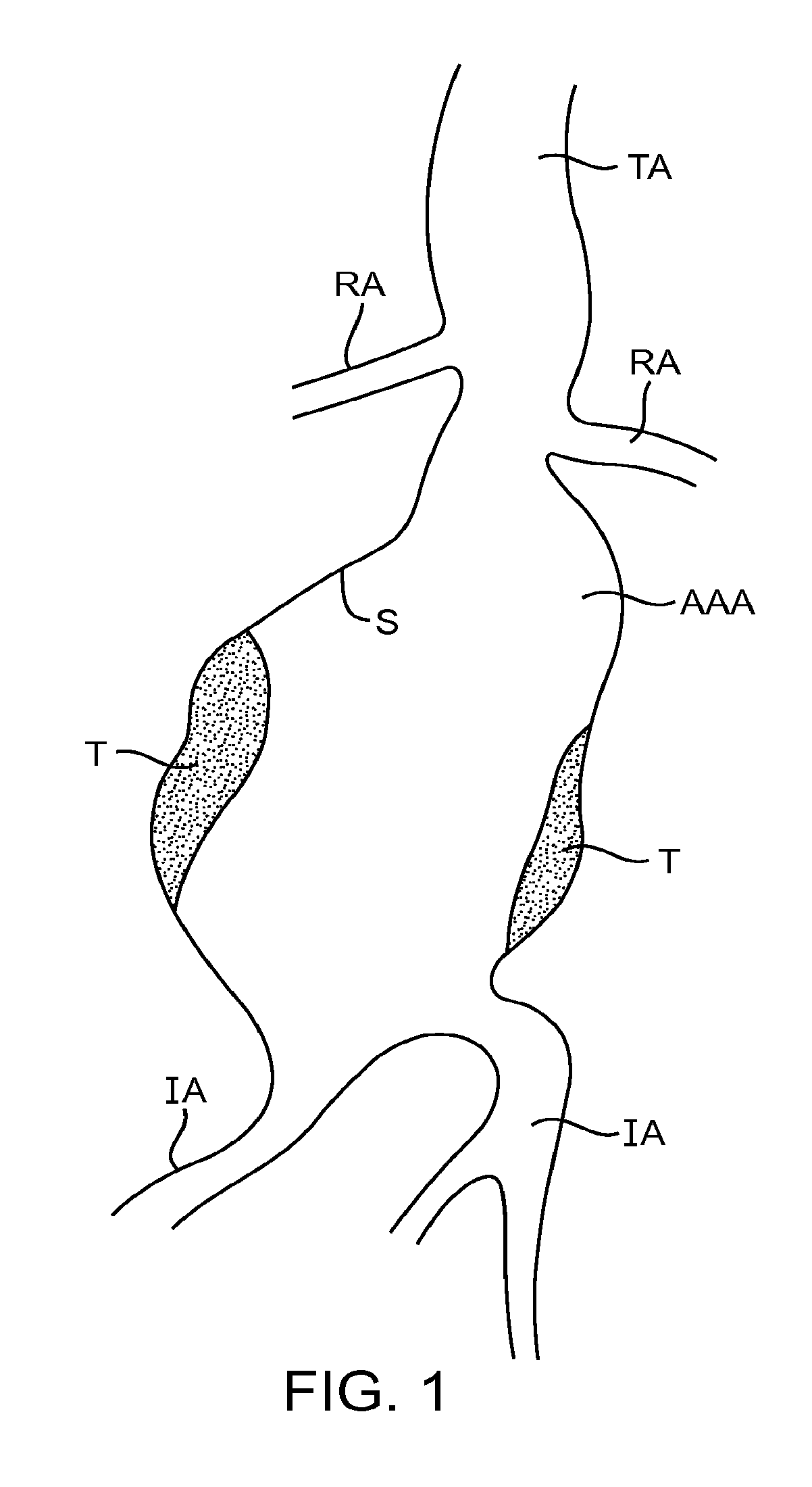
[0024] FIG. 1 illustrates the anatomy of an infrarenal abdominal aortic aneurysm.
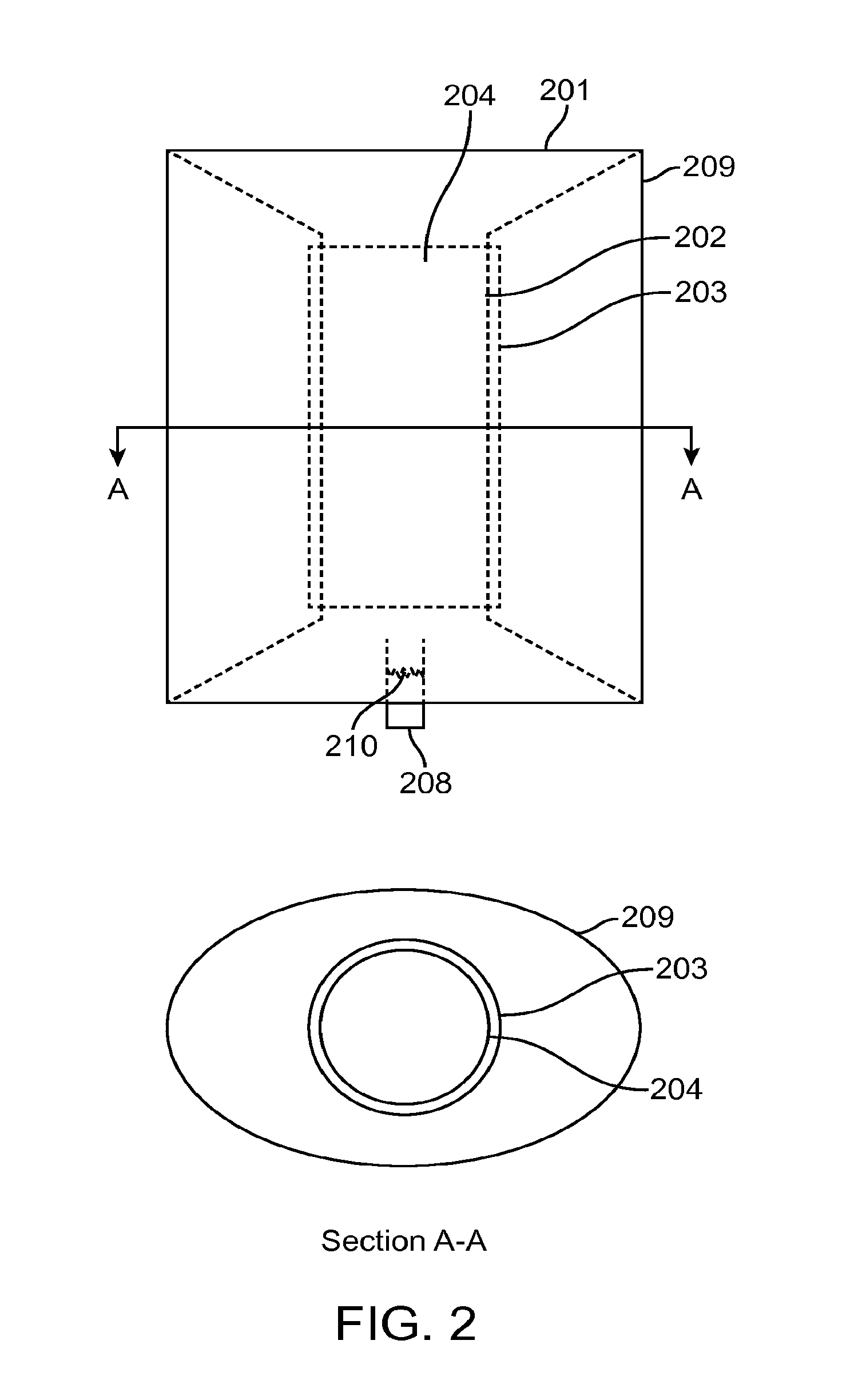
[0025] FIG. 2 illustrates a filling structure comprising a multi-layer reinforced inner lumen.
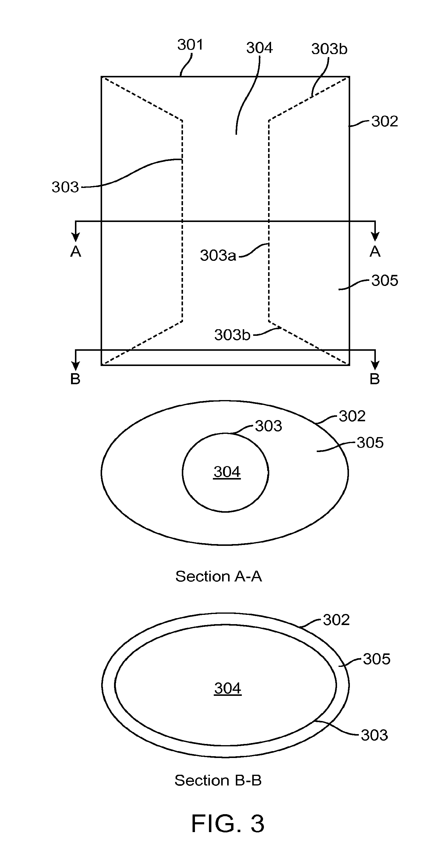
[0026] FIG. 3 illustrates a filling structure comprising an inner lumen with tapered ends.
[0027] FIG. 4 illustrates a filling structure comprising multiple compartments.
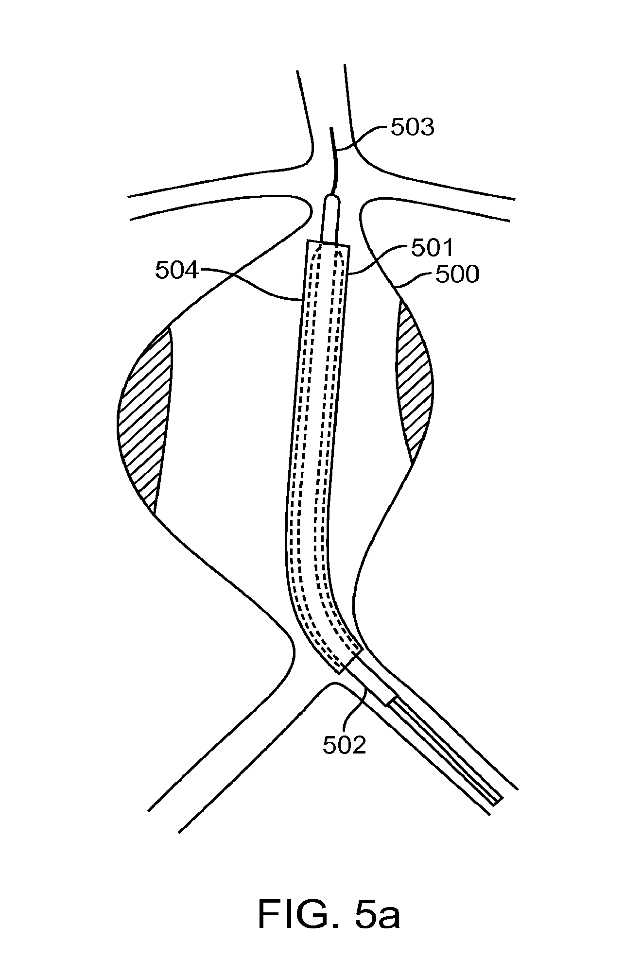
[0028] FIGS. 5A-5D illustrate an exemplary method of deploying a filling structure in an aneurysm.
DETAILED DESCRIPTION OF THE INVENTION
[0029] Referring to FIG. 1, the anatomy of an infrarenal abdominal aortic aneurysm comprises the thoracic aorta (TA) having renal arteries (RA) at its distal end above the iliac arteries (IA). The abdominal aortic aneurysm (AAA) typically forms between the renal arteries (RA) and the iliac arteries (IA) and may have regions of mural thrombus (T) over portions of its inner surface (S).
[0030] FIG. 2 illustrates a filling structure 201 embodying aspects of the invention. Filling structure 201 comprises central lumen 204 defined by luminal wall 202, outer wall 209, and reinforcing sleeve 203. Fill tube 208 is attached to a cannula during placement of the device, and allows hardenable filling material to enter the interior volume of the filling structure, then seals itself to prevent backflow of filling material when the cannula is removed. Fill tube 208 may comprise a tear line 210 created by a partial perforation or notched edges. The tear line allows part or the entire exterior portion of the fill tube to be removed when the fill cannula is removed so that none of the fill tube protrudes beyond the filling structure once the filling structure is placed. This prevents contact between the fill tube and the artery wall, reducing the risk of thrombosis.
[0031] Still referring to FIG. 2, reinforcing sleeve 203 may be laminated, welded, sewn, or adhesively attached to central lumen 204, or may be a separate sleeve that is placed over central lumen 204 during the assembly process. Both reinforcing sleeve 203 and central lumen 204 may vary in diameter in order to conform more closely to the natural diameter of the target artery, particularly at the ends. This may afford superior sealing by matching the diameter of the filling structure more closely to the diameter of the neck of the aneurysm.
[0032] As shown in FIG. 3, a filling structure 301 may be constructed such that inner lumen 303 varies in diameter over the length of the filling structure in order to increase filled volume 305 and improve sealing against one or more necks of the aneurysm. In one aspect, the filling structure 301 has an exterior wall 302 and a lumen 303. The lumen 303 has a larger diameter 304 at each end than at a point therebetween, and may comprise a cylindrical middle portion 303a with one or more conical end portions 303b. The slope of the shoulder of conical end portions 303b may be chosen to control the shape of filling structure 301 after it is filled. Choosing a maximum diameter of conical section 303b that is close to the outside diameter of the filling structure results in a more circular cross-section, while a smaller maximum diameter relative to the outside diameter of filling structure 301 results in an oval or eye-shaped cross-section. Other taper profiles for the inner lumen may be selected; for example it is possible to use a parabolic or hyperbolic profile to provide a continuous transition from one inner diameter to another, which may reduce turbulent flow in the lumen. Note that the foregoing description is for exemplary purposes and is not meant to exclude other diameter profiles.
[0033] FIG. 4 illustrates a filling structure 401 comprising at least two filling compartments. Endoframe 402 may be used to support the filling structure while it is being filled, maintaining a diameter of interior lumen 403. Inner compartment 404 may be connected directly to a fill valve 407 such that filling material enters compartment 404 forming an inner polymer jacket 405 before flowing to outer compartment 406. In this aspect the two compartments may be in fluid communication with each other, optionally with a restriction between the two compartments such that the viscosity of the filling medium inflates the inner compartment fully before filling the outer compartment. U.S. patent application Ser. No. 12/429,474 (Attorney Docket No. 025925-002610US) discloses various delivery system configurations and methods for delivering and deploying a filling structure that may be used for any of the filling structures disclosed herein, the entire contents of which are incorporated herein by reference.
[0034] In an alternate aspect, inner compartment 404 may be separated from outer compartment 406 and each compartment may have a separate fill valve similar to fill valve 407. In this case valve 407 communicates with the inner compartment and another fill valve (not shown) communicates with the outer compartment. This permits the use of two different filling media, each with potentially different material properties. For example, the inner compartment-filling medium may be selected for a fast cure time to allow rapid removal of the endoframe 402, or for a larger bulk modulus to provide enhanced resistance to pulsatile pressure. The outer compartment-filling medium may for example be selected for enhanced adhesion to an inner wall of filling structure 401. Separate fill valves also allow the compartments to be filled in a controlled order. In one aspect, the inner compartment is filled before the outer compartment to allow the inner compartment to be fully filled, providing a solid structure for resisting pulsatile pressure. The outer compartment is then filled sufficiently to fill the aneurysm sac without overloading the artery wall.
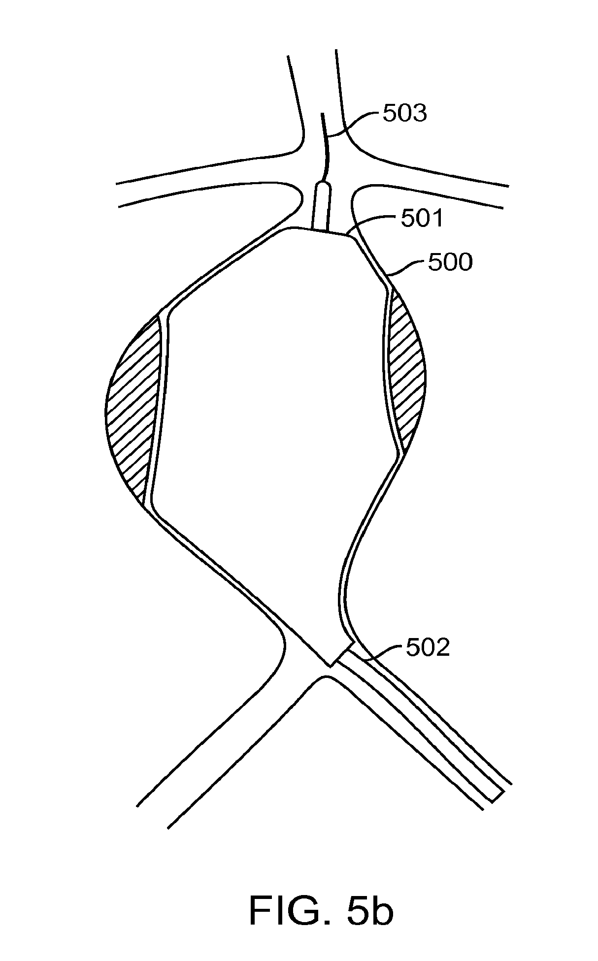
[0035] Referring now to FIG. 5a, we describe an exemplary method of placing and filling a multi-partition filling structure in an aneurysm 500. Furled filling structure 501 is introduced to the aneurysm on guidewire 503 and cannula 502. Sheath 504 is withdrawn to release filling structure 501. Cannula 502 contains guidewire 503 as well as one or more optional lumens (not illustrated) for filling the filling structure compartments, and possibly for introducing an endoframe and expansion balloon, as well as lines permitting detachment of the filling structure and other components from the cannula for deployment.
[0036] Continuing to FIG. 5b, the unfurled filling structure may be unfurled completely by filling with a solution containing contrast agent, saline, combinations thereof, as well as other fluids. This is advantageous since the walls of the filling structure may stick against adjacent walls, especially after terminal sterilization and storage. Once unfurled, the volume of solution required to unfurl may be used as an estimate of the volume of hydrogel mix to introduce in order to fill the aneurysm sac completely without overpressure on the wall.
[0037] Continuing to FIG. 5c, endoframe 505 may be introduced into the inner lumen of filling structure 501 to support the inner lumen during the hydrogel filling step. Endoframe 505 may be self-expanding, or may be expanded by an expandable member such as a balloon (not illustrated) introduced via cannula 502. Endoframe 505 may be withdrawn after the filling step, or may be left in place indefinitely.
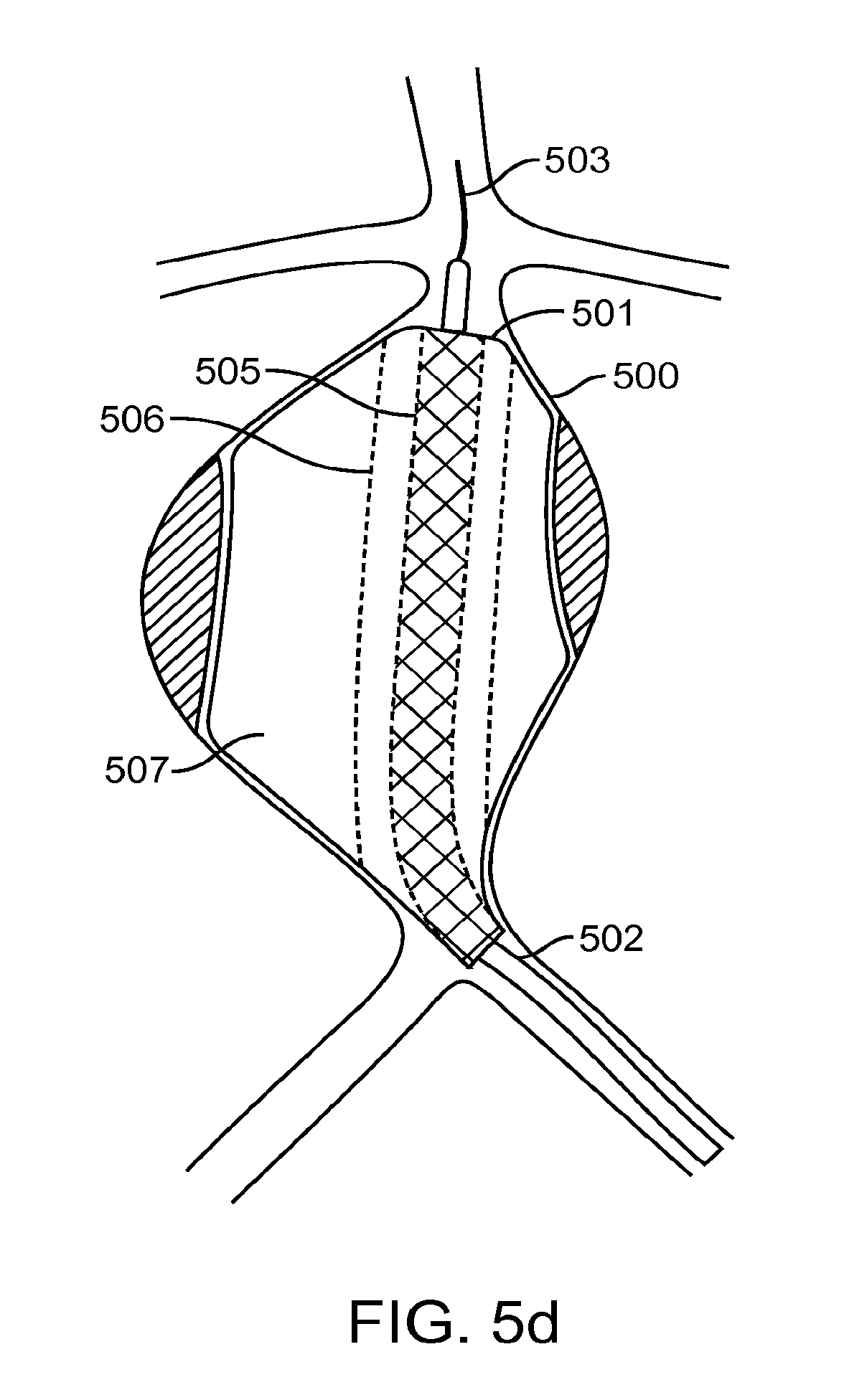
[0038] Continuing to FIG. 5d, uncured liquid hydrogel is introduced through cannula 502 into inner partition 506 of filling structure 501. In one aspect, inner partition 506 may be in restricted fluid communication with outer partition 507 of filling structure 501. In this case, once inner partition 506 is filled, hydrogel flows to outer partition 507 via a passageway. The hydrogel's viscosity in combination with the cross-section area of the passageway causes inner partition 506 to stay inflated while outer partition 507 fills with the remaining volume of hydrogel until filling structure 501 completely fills the aneurysm sac. In another aspect, inner partition 506 and outer partition 507 may be filled by independent filling tubes (not illustrated) in cannula 502. In this aspect, inner partition 506 is filled until a measured pressure of the hydrogel reaches a threshold pressure, or until a dispensed volume of hydrogel reaches a threshold volume indicating complete filling of inner partition 506. Then outer partition 507 is filled with the remaining volume of hydrogel as estimated in the pre-fill step described previously. Note that the filling structure may comprise more than two compartments, in which case the filling process continues until all compartments are properly and completely filled. Once the hydrogel cures--preferably in less than ten minutes, and more preferably in less than five minutes, and even more preferably in less than about 4 minutes, the filling tubes may be detached from the filling structure and the cannula and guidewire may be withdrawn. Note that this process may be conducted on two filling structures simultaneously, with one filling structure inserted through each iliac artery. Filling of the filling structure may be performed with the endoframe expanded fully or partially, or the endoframe may be unexpanded. Additionally, the expandable member may be partially or fully expanded, or unexpanded during the filling procedure. Filling may also be visualized using fluoroscopy, ultrasound, or other methods in order to ensure that the filling structure properly expands and fills the aneurismal space.
[0039] While the above is a complete description of the preferred embodiments of the invention, various alternatives, modifications, and equivalents may be used. Therefore, the above description should not be taken as limiting in scope of the invention which is defined by the appended claims.
* * * * *
D00000
D00001
D00002
D00003
D00004
D00005
D00006
D00007
D00008
XML
uspto.report is an independent third-party trademark research tool that is not affiliated, endorsed, or sponsored by the United States Patent and Trademark Office (USPTO) or any other governmental organization. The information provided by uspto.report is based on publicly available data at the time of writing and is intended for informational purposes only.
While we strive to provide accurate and up-to-date information, we do not guarantee the accuracy, completeness, reliability, or suitability of the information displayed on this site. The use of this site is at your own risk. Any reliance you place on such information is therefore strictly at your own risk.
All official trademark data, including owner information, should be verified by visiting the official USPTO website at www.uspto.gov. This site is not intended to replace professional legal advice and should not be used as a substitute for consulting with a legal professional who is knowledgeable about trademark law.