Safety Helmet
Deshpande; Shantanu ; et al.
U.S. patent application number 16/246935 was filed with the patent office on 2019-08-01 for safety helmet. This patent application is currently assigned to Klein Tools, Inc.. The applicant listed for this patent is Klein Tools, Inc.. Invention is credited to Shantanu Deshpande, Kingston Wong.
| Application Number | 20190231016 16/246935 |
| Document ID | / |
| Family ID | 67391122 |
| Filed Date | 2019-08-01 |


| United States Patent Application | 20190231016 |
| Kind Code | A1 |
| Deshpande; Shantanu ; et al. | August 1, 2019 |
Safety Helmet
Abstract
A safety helmet includes an outer shell having a front receptacle disposed on a front side of the outer shell and a rear receptacle disposed on a rear side of the outer shell. A first accessory device having a first mating receptacle formed thereon is releasably mountable onto each of the front receptacle or the rear receptacle of the outer shell, and a second accessory device having a second mating receptacle formed thereon is releasably mountable onto each of the front receptacle or the rear receptacle of the outer shell.
| Inventors: | Deshpande; Shantanu; (Glenview, IL) ; Wong; Kingston; (Beach Park, IL) | ||||||||||
| Applicant: |
|
||||||||||
|---|---|---|---|---|---|---|---|---|---|---|---|
| Assignee: | Klein Tools, Inc. Lincolnshire IL |
||||||||||
| Family ID: | 67391122 | ||||||||||
| Appl. No.: | 16/246935 | ||||||||||
| Filed: | January 14, 2019 |
Related U.S. Patent Documents
| Application Number | Filing Date | Patent Number | ||
|---|---|---|---|---|
| 62622472 | Jan 26, 2018 | |||
| 62645491 | Mar 20, 2018 | |||
| Current U.S. Class: | 1/1 |
| Current CPC Class: | A42B 3/04 20130101; A42B 3/0446 20130101 |
| International Class: | A42B 3/04 20060101 A42B003/04 |
Claims
1. A safety helmet, comprising: an outer shell adapted to be worn by a user, the outer shell having a front side and a rear side, wherein the outer shell is reversible such that one of the front side or the rear side is oriented above a face of the user when the outer shell is worn by the user; a front receptacle disposed on the front side of the outer shell; a rear receptacle disposed on the rear side of the outer shell, wherein the front receptacle and the rear receptacle are of identical construction; an accessory device having a mating receptacle formed thereon, the accessory device being releasably mountable onto each of the front receptacle and the rear receptacle of the outer shell.
2. The safety helmet of claim 1, wherein the front receptacle includes a receiver slot flanked by raised walls and including a stop, wherein the accessory device includes a spring tab with a pawl, and wherein the receiver slot aligns the accessory device therein, the raised walls retain the accessory device therebetween, and the pawl engages the stop to releasably mount the accessory device in the front receptacle.
3. The safety helmet of claim 1, wherein the outer shell is made from a molded plastic material.
4. A safety helmet, comprising: an outer shell adapted to be worn by a user, the outer shell having a front side and a rear side, wherein the outer shell is reversible such that one of the front side or the rear side is oriented above a face of the user when the outer shell is worn by the user; a front receptacle disposed on the front side of the outer shell; a rear receptacle disposed on the rear side of the outer shell; a first accessory device having a first mating receptacle formed thereon, the first accessory device being releasably mountable onto each of the front receptacle or the rear receptacle of the outer shell; and a second accessory device having a second mating receptacle formed thereon, the second accessory device being releasably mountable onto each of the front receptacle or the rear receptacle of the outer shell.
5. The safety helmet of claim 4, wherein the front receptacle includes a receiver slot flanked by raised walls and including a stop, wherein the first accessory device includes a spring tab with a pawl, and wherein the receiver slot aligns the first accessory device therein, the raised walls retain the first accessory device therebetween, and the pawl engages the stop to releasably mount the first accessory device in the front receptacle.
6. The safety helmet of claim 4, wherein the outer shell is made from a molded plastic material.
7. A safety helmet, comprising: an outer shell adapted to be worn by a user, the outer shell having a front side and a rear side, wherein the outer shell is reversible such that one of the front side or the rear side is oriented above a face of the user when the outer shell is worn by the user; a front receptacle disposed on the front side of the outer shell; a rear receptacle disposed on the rear side of the outer shell; wherein the front receptacle includes a front set of terminals associated therewith, and the rear receptacle includes a rear set of terminals associated therewith; and wherein a set of conductors is connected between the front set of terminals and the rear set of terminals.
8. The safety helmet of claim 7, wherein the set of conductors are integrated into the outer shell.
9. The safety helmet of claim 7, wherein the outer shell is made from a molded plastic material, and wherein the front set of terminals and the rear set of terminals are molded into the outer shell.
10. The safety helmet of claim 7, wherein a first accessory device is connected to the front receptacle and is a consumer of power, wherein a second accessory device is connected to the rear receptacle and is a power storage device, and wherein a circuit providing power from the second accessory device to the first accessory device is created while the first accessory device and the second accessory device are mounted onto the front receptacle and rear receptacles.
11. The safety helmet of claim 10, wherein each of the first accessory device and the second accessory device is a consumer of power a having power source integrated therewith.
12. The safety helmet of claim 11, wherein the power source of the first accessory device and the power source of the second accessory device are in electrical contact with one another to share power through the circuit.
13. The safety helmet of claim 10, where in the front receptacle and the rear receptacle are of identical construction.
14. A method for using a protective device, comprising: providing an outer shell adapted to be worn by a user, the outer shell having a front side and a rear side, wherein the outer shell is reversible such that the front side or the rear side is oriented above a face of the user when the user wears the outer shell; providing a front receptacle disposed on the front side of the outer shell; providing a rear receptacle disposed on the rear side of the outer shell; releasably attaching an accessory device having a mating receptacle formed thereon into one of the front receptacle or the rear receptacle; and detaching the accessory device and reattaching the accessory device into another one of the front receptacle or the rear receptacle.
15. The method of claim 14, further comprising electrically interconnecting terminals associated with the front and rear receptacles using a set of conductors.
16. The method of claim 15, wherein the outer shell is made from a molded plastic material, and wherein the terminals are molded into the outer shell.
17. The method of claim 15, further comprising: connecting an additional accessory device into the front or rear receptacles; and transferring electrical power between the accessory device and the additional accessory device through the set of conductors.
18. The method of claim 17, wherein the accessory device is a lantern and wherein the additional accessory device includes one or more batteries.
19. The method of claim 15, wherein the set of conductors is molded into the outer shell.
20. The method of claim 14, where in the front receptacle and the rear receptacle are of identical construction.
Description
CROSS-REFERENCE TO RELATED APPLICATIONS
[0001] This patent application claims the benefit of U.S. Provisional Patent Application No. 62/622,472, filed Jan. 26, 2018, and U.S. Provisional Patent Application No. 62/645,491, filed Mar. 20, 2018, each of which disclosure is incorporated herein by reference.
BACKGROUND OF THE DISCLOSURE
[0002] The present disclosure relates to personal protection devices and, more particularly, safety helmets for use to protect the wearer from falling objects. Such helmets are commonly also referred to as "hard hats." Various types of safety helmets are commonly used in in several industries, many of which include mounted personal illumination devices commonly called headlamps, typically powered by a direct current power source (either replaceable or rechargeable chemical cells). In the simplest of such devices, the headlamp is permanently mounted to the safety helmet in a fixed orientation at the front of the safety helmet. In other such devices, a mounting bracket is included at the front of the helmet to allow for a headlamp to be inserted.
[0003] One common method of mounting headlamps onto a safety helmet is by using an elastic band to conform and adhere to the exterior of the safety helmet, and then mounting the portable device onto the elastic band. While use of elastic bands can permit mounting of the headlamp at any orientation relative to the safety helmet, and also mounting of additional devices onto a single band, switching between orientations is difficult. Moreover, band-type mounting systems are prone to slipping off from the safety helmet, especially when lubricating fluids may fall on the helmet and enter the interface between the helmet's exterior and the band, thus requiring constant readjustment by the user.
[0004] Another common issue with known safety helmet headlamp arrangements is the connection of a power source to the headlamp. Portable power sources such as batteries are known to be heavy and bulky. When integrated with the headlamp, which is worn on the front facing side of the helmet, headlamps with integrated power sources tend to pull the helmet down, especially when the wearer is looking down. To reduce the weight of headlamps, manufacturers decrease the size of the batteries that are integrated therewith, which also decreases their useful life and will also decrease the lumen output of the headlamp. In certain applications where long life and higher light intensity is desired such as in underground mines, headlamps are typically connected to a power source via a wire, which leads to heavier and bulkier batteries worn around the user's waist. The wire leading to the batteries, however, can present a nuisance to the user and also increases the chances of unsafe conditions as it may become snagged as the user is moving around.
BRIEF SUMMARY OF THE DISCLOSURE
[0005] In one aspect, the present disclosure describes a safety helmet. The safety helmet includes an outer shell adapted to be worn by a user. The outer shell has a front side and a rear side, wherein the outer shell is reversible such that one of the front side or the rear side is oriented above a face of the user when the outer shell is worn by the user. A front receptacle is disposed on the front side of the outer shell, and a rear receptacle is disposed on the rear side of the outer shell. The front receptacle and the rear receptacle are of identical construction. An accessory device has a mating receptacle formed thereon, and is releasably mountable onto each of the front receptacle and the rear receptacle of the outer shell.
[0006] In another aspect, the disclosure describes a safety helmet, which includes an outer shell adapted to be worn by a user. The outer shell has a front side and a rear side. The outer shell is reversible such that one of the front side or the rear side is oriented above a face of the user when the outer shell is worn by the user. A front receptacle is disposed on the front side of the outer shell, and a rear receptacle is disposed on the rear side of the outer shell. A first accessory device has a first mating receptacle formed thereon and is releasably mountable onto each of the front receptacle or the rear receptacle of the outer shell, and a second accessory device has a second mating receptacle formed thereon and is releasably mountable onto each of the front receptacle or the rear receptacle of the outer shell.
[0007] In yet another aspect, the disclosure describes a safety helmet that includes an outer shell adapted to be worn by a user and having a front side and a rear side. The outer shell is reversible such that one of the front side or the rear side is oriented above a face of the user when the outer shell is worn by the user. The safety helmet further includes a front receptacle disposed on the front side of the outer shell, and a rear receptacle disposed on the rear side of the outer shell. The front receptacle includes a front set of terminals associated therewith, the rear receptacle includes a rear set of terminals associated therewith, and a set of conductors is connected between the front set of terminals and the rear set of terminals.
[0008] In yet another aspect, the disclosure describes a method for using a protective device. The method includes providing an outer shell adapted to be worn by a user, the outer shell having a front side and a rear side, wherein the outer shell is reversible such that the front side or the rear side is oriented above a face of the user when the user wears the outer shell. The method further includes providing a front receptacle disposed on the front side of the outer shell, and providing a rear receptacle disposed on the rear side of the outer shell. The method also includes releasably attaching an accessory device having a mating receptacle formed thereon into one of the front or rear receptacle, detaching the accessory device, and reattaching the accessory device into another one of the front or rear receptacle.
BRIEF SUMMARY OF THE SEVERAL VIEWS OF THE DRAWINGS
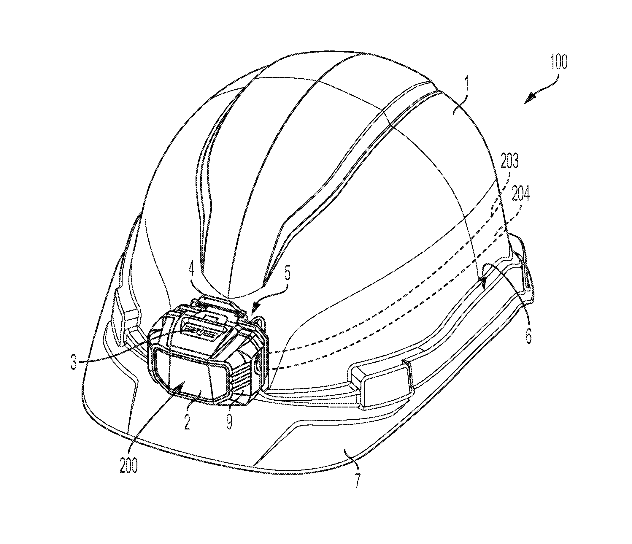
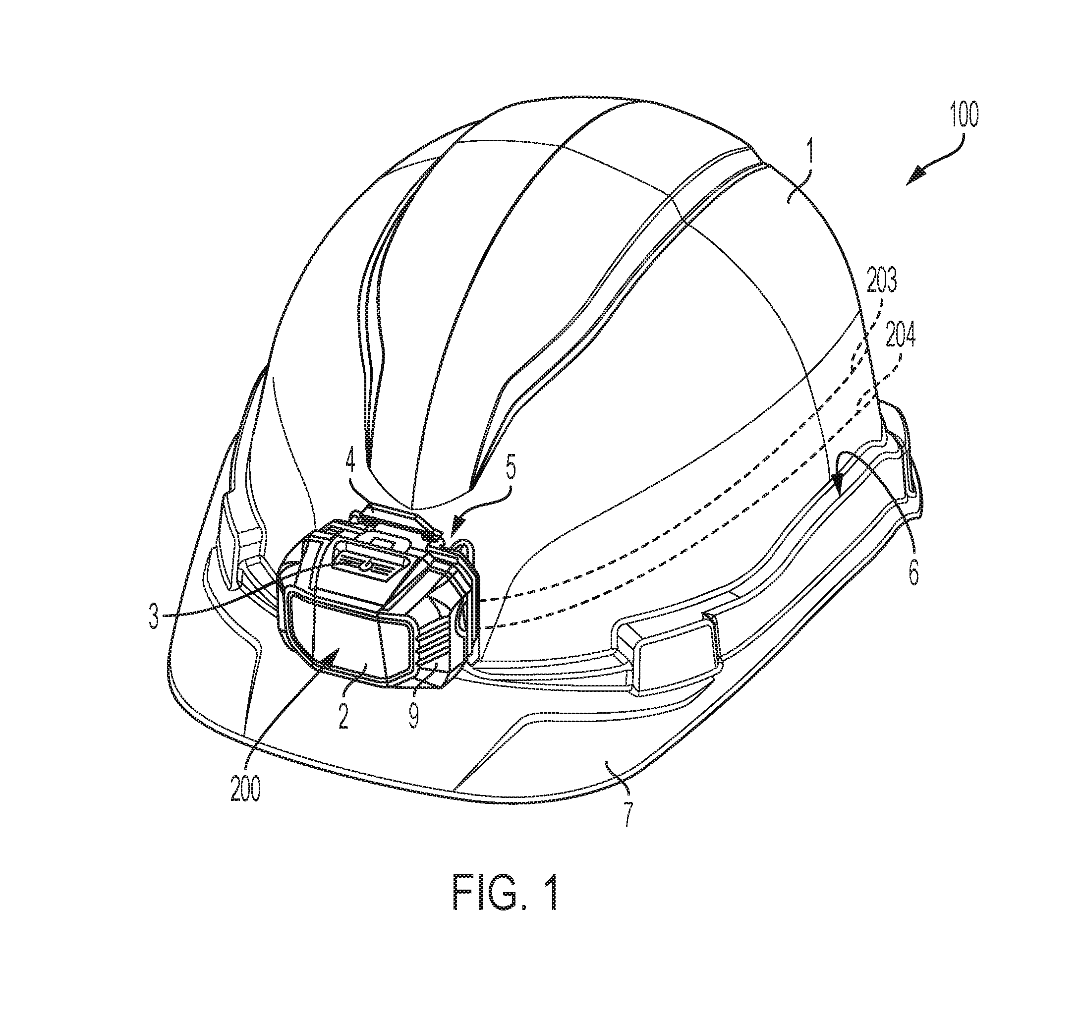
[0009] FIGS. 1 and 2 are front and rear perspective views of a safety helmet in accordance with the disclosure.
[0010] FIG. 3 is a front view of the safety helmet of FIG. 1.
[0011] FIG. 4 is a rear view of a device that is connectable to the safety helmet of FIG. 1 in accordance with the disclosure.
[0012] FIG. 5 is a cross section of the safety helmet of FIG. 1.
[0013] FIG. 6 is an enlarged detail cross section of the helmet of FIG. 1.
[0014] FIG. 7 is a side view of an alternative embodiment.
DETAILED DESCRIPTION OF A PREFERRED EMBODIMENT
[0015] The present invention relates to the field of personal protection devices and, more particularly, safety helmets. The safety helmets in accordance with the disclosure include two mounts, one on either the front or back facing sides of the helmet, which permit connection of removable modules onto the helmet such as headlamps, cameras, speakers, larger capacity batteries, cellphones, and the like. In one embodiment, the helmet includes an integrated, non-removable power source and integrated electrical leads or conductors to a port for a removable device. In this way, the removable device such as a headlamp can be made lighter without sacrificing battery power output or electrical potential. The headlamp, which may include its own power source that is chargeable by the helmet, may be removed and used as a flashlight before being replaced onto the helmet for charging.
[0016] A safety helmet 100 in accordance with one embodiment of the present disclosure is shown in FIG. 1. The safety helmet 100 includes a detachably mounted, headlamp device 200. The safety helmet 100 includes a hard outer shell 1 designed to protect the head of the wearer from injury and a brim 7 designed to shield the user's eyes from sunlight or falling debris. Accessory slots 6 may be present to accept various accessories. The headlamp device 200 features a headlamp body 9, a light source 2, a power switch 3 to activate the light source 2, and a mounting bracket 4 to removeably attach the headlamp device 200 to the safety helmet 100.
[0017] Connection of the headlamp device 200, which is shown as one exemplary embodiment of a device that can be connected to the safety helmet 100, is accomplished by releasable engagement of the mounting bracket 4 to a front tapered receiver slot 5 of the safety helmet 100. The front tapered receiver slot 5 is disposed on the front of hard outer shell 1 of the safety helmet 100. In this configuration, the light emanating from the light source 2 projects forward from the safety helmet 100, illuminating the area in front of a user when the safety helmet is in its standard orientation in which the brim 7 is disposed over the wearer's face.
[0018] The mounting bracket 4 and front tapered receiver slot 5 are one exemplary embodiment for releasably connecting the device 200 to the safety helmet 100. As also shown in FIGS. 3 and 4, the front tapered receiver slot 5 includes a tapered channel 16 formed between a pair of raised sidewalls 18 and a protruding nub 17 extending from the surface of the hard outer shell 1 of the safety helmet 100. The mounting bracket 4 is in the form of a tapered clip 19 conforming to the tapered channel 16 such that it is retained by the raised sidewalls 18 when it is inserted into the tapered channel. A slot 20 in the tapered clip 19 receives the protruding nub 17 on the hard outer shell 1 of the safety helmet 100 locking it into place. The mounting bracket 4 can be detached from the front tapered receiver slot 5 by pulling on the release lever 21 of the tapered clip 19, which disengages the protruding nub 17 from the slot 20 to allow the headlamp device 200 to be lifted out of the tapered channel 16.
[0019] The safety helmet 100 is shown from a rear perspective in FIG. 2. As shown, the safety helmet 100 includes a second device 201 mounted on the rear side of the hard outer shell 1. While in certain embodiments the second device 201 may be releasably mounted to the safety helmet 100 using a second tapered receiver slot, similar to the front tapered receiver slot 5 on the front of the helmet (FIG. 1), in the illustrated embodiment, the second device 201 is non-releasably or, generally permanently, mounted onto the safety helmet 100. The second device shown in FIG. 2 is a battery pack or power storage device that houses disposable or rechargeable battery power cells. The battery cells in the second device 201 are configured to provide electrical potential in the form of a direct current (DC) electrical power output into two conductors, 203 and 204 (shown in FIG. 1), which are integrated into the hard outer shell 1.
[0020] The conductors 203 and 204, which are shown in dashed lines in FIGS. 1 and 2, are metal conductors that can be made from copper, aluminum, steel, zinc or the like, and are molded into the thermoplastic material of the hard outer shell 1 of the safety helmet 100. In one embodiment, the conductors can be placed into a mold used for injection molding of the hard outer shell 1 such that the plastic used to construct the hard outer shell 1 can be over-molded around the conductors to conceal and protect the conductors as shown, for example, in FIG. 6. Placement of the conductors can be selected depending on the particular safety requirements of the helmet. As shown, the conductors are placed along an outer region of the helmet, away from the wearer's head.
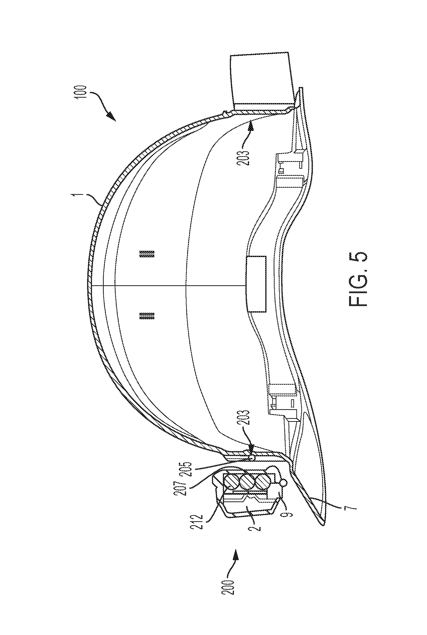
[0021] At one end, the conductors 203 and 204 are permanently and electrically connected to two poles of the battery cells in the second device 201 such that an electrical potential created by the battery cells is available through the conductors. At another end the conductors 203 and 204 terminate at terminals 205 and 206, as shown in FIG. 3, which present bare surfaces for achieving a releasable electrical connection with corresponding terminals 207 and 208 formed on the back side of the device 200 that is connectable to the front tapered receiver slot 5, as shown in FIG. 4. In this way, when the device 200 is mechanically connected to the receiver slot, an electrical connection between the first device, for example, the headlamp device 200 and the second device 201 is also established and maintained while the device 200 is mounted onto the safety helmet 100.
[0022] FIG. 5 a side, section view through the safety helmet 100 shown in FIG. 1, and FIG. 6 is an enlarged detail view to illustrate the connections of the electrical conductors through the material of the hard outer shell 1 to the terminals 207 and 208 (only one visible) and also to the additional device 201. Also visible here are secondary, rechargeable batteries 212 used within the device 200, which can be charged through the conductors from the second device 201 and which also allow the device 200 to be used autonomously, if desired. In the embodiment shown, the rechargeable batteries 212 used in the device 200 have a smaller electrical capacity than batteries in the second device 201 to allow the device to be recharged while connected to the safety helmet 100, provided that the electrical potential of the second device 201 is higher than the device 200 and charging of the device 200 can occur. The recharging of the device 200 advantageously permits use of the device to be used autonomously when separated from the safety helmet 100, and then reconnected to the helmet for charging from the second device 201. While charging, the device 200 can also operate, for example, to provide light, by drawing sufficient electrical power from the second device to both operate and charge the device 200 because of the larger electrical capacity of the second device 201. When the second device 201 is connected to a power source for charging, and while the device 201 is connected, both devices can be charged simultaneously to increase to the total charge available on the safety helmet 100. Moreover, the second device 201 can include a shutoff or diode integrated therewith, which only permits flow of electrical power in the form of electrical DC current from the second device 201 to the device 200, but not in the opposite direction.
[0023] The devices 200 and 201 may be embodied as various types of devices or accessories. For example, in addition to headlamps or battery packs, the devices may be embodied as a speaker, which can be connected to an audio player or similar device by known methods, a holder or bracket for another device such as a camera, smartphone or the like, a blinking or otherwise illuminated light that marks the location of the user, a GPS receiver or tag, and the like.
[0024] An alternative embodiment is shown in FIG. 7, in which a plurality of electrical devices, in this case, illumination devices 210, are integrated around the helmet and connected to be powered by the second device 201. For example, the illumination devices 210 may be low-powered LED lights or strobes that can be illuminated and used as safety devices, in addition to reflective devices, in low light environments. The electrical connections to power the illumination devices 210 can be integrated into the hard outer shell in a fashion similar to the conductors 203 and 204, and be electrically connected therewith.
[0025] All references, including publications, patent applications, and patents, cited herein are hereby incorporated by reference to the same extent as if each reference were individually and specifically indicated to be incorporated by reference and were set forth in its entirety herein.
[0026] The use of the terms "a" and "an" and "the" and "at least one" and similar referents in the context of describing the invention (especially in the context of the following claims) are to be construed to cover both the singular and the plural, unless otherwise indicated herein or clearly contradicted by context. The use of the term "at least one" followed by a list of one or more items (for example, "at least one of A and B") is to be construed to mean one item selected from the listed items (A or B) or any combination of two or more of the listed items (A and B), unless otherwise indicated herein or clearly contradicted by context. The terms "comprising," "having," "including," and "containing" are to be construed as open-ended terms (i.e., meaning "including, but not limited to,") unless otherwise noted. Recitation of ranges of values herein are merely intended to serve as a shorthand method of referring individually to each separate value falling within the range, unless otherwise indicated herein, and each separate value is incorporated into the specification as if it were individually recited herein. All methods described herein can be performed in any suitable order unless otherwise indicated herein or otherwise clearly contradicted by context. The use of any and all examples, or exemplary language (e.g., "such as") provided herein, is intended merely to better illuminate the invention and does not pose a limitation on the scope of the invention unless otherwise claimed. No language in the specification should be construed as indicating any non-claimed element as essential to the practice of the invention.
[0027] Preferred embodiments of this invention are described herein, including the best mode known to the inventors for carrying out the invention. Variations of those preferred embodiments may become apparent to those of ordinary skill in the art upon reading the foregoing description. The inventors expect skilled artisans to employ such variations as appropriate, and the inventors intend for the invention to be practiced otherwise than as specifically described herein. Accordingly, this invention includes all modifications and equivalents of the subject matter recited in the claims appended hereto as permitted by applicable law. Moreover, any combination of the above-described elements in all possible variations thereof is encompassed by the invention unless otherwise indicated herein or otherwise clearly contradicted by context.
* * * * *
D00000
D00001
D00002
D00003
D00004
D00005
XML
uspto.report is an independent third-party trademark research tool that is not affiliated, endorsed, or sponsored by the United States Patent and Trademark Office (USPTO) or any other governmental organization. The information provided by uspto.report is based on publicly available data at the time of writing and is intended for informational purposes only.
While we strive to provide accurate and up-to-date information, we do not guarantee the accuracy, completeness, reliability, or suitability of the information displayed on this site. The use of this site is at your own risk. Any reliance you place on such information is therefore strictly at your own risk.
All official trademark data, including owner information, should be verified by visiting the official USPTO website at www.uspto.gov. This site is not intended to replace professional legal advice and should not be used as a substitute for consulting with a legal professional who is knowledgeable about trademark law.