Cap With Unique Profile
Huynh; Chuong
U.S. patent application number 15/975667 was filed with the patent office on 2019-08-01 for cap with unique profile. The applicant listed for this patent is Publish Brand, Inc.. Invention is credited to Chuong Huynh.
| Application Number | 20190231014 15/975667 |
| Document ID | / |
| Family ID | 67391189 |
| Filed Date | 2019-08-01 |


View All Diagrams
| United States Patent Application | 20190231014 |
| Kind Code | A1 |
| Huynh; Chuong | August 1, 2019 |
CAP WITH UNIQUE PROFILE
Abstract
A cap including a dome portion, wherein one or more panels that form the dome portion and one or more darts define a shape of the dome portion, wherein one or more terminal ends of adjacent panels are coupled by one or more seams and the one or more darts extend along a length of the one or more panels.
| Inventors: | Huynh; Chuong; (Huntington Beach, CA) | ||||||||||
| Applicant: |
|
||||||||||
|---|---|---|---|---|---|---|---|---|---|---|---|
| Family ID: | 67391189 | ||||||||||
| Appl. No.: | 15/975667 | ||||||||||
| Filed: | May 9, 2018 |
Related U.S. Patent Documents
| Application Number | Filing Date | Patent Number | ||
|---|---|---|---|---|
| 62625284 | Feb 1, 2018 | |||
| Current U.S. Class: | 1/1 |
| Current CPC Class: | A42C 1/00 20130101; A42B 1/02 20130101; A42B 1/061 20130101; A42B 1/22 20130101; A42C 5/00 20130101 |
| International Class: | A42B 1/02 20060101 A42B001/02; A42B 1/22 20060101 A42B001/22; A42C 5/00 20060101 A42C005/00; A42C 1/00 20060101 A42C001/00 |
Claims
1. A cap comprising: one or more panels that form a dome portion, wherein one or more terminal ends of adjacent panels are coupled by one or more seams; and one or more darts that define a shape of the dome portion; wherein the one or more darts extend along a length of the one or more panels.
2. The cap from claim 1, wherein the one or more darts comprise a first dart and a second dart, wherein a length of the first dart is different from a length of a second dart.
3. The cap from claim 1, wherein the one or more darts converge on a top portion of the dome portion.
4. The cap from claim 3, wherein the one or more seams converge on a top portion of the dome portion.
5. The cap from claim 4, wherein the one or more seams extend to a bottom portion of the dome portion.
6. The cap from claim 5, wherein the one or more darts extend to a bottom exterior portion of the dome portion.
7. The cap from claim 5, wherein the one or more darts terminate before a bottom exterior portion of the dome portion.
8. The cap from claim 1, wherein the one or more panels comprise a first panel and a second panel, wherein a width of the first panel is different from a width of a second panel.
9. The cap from claim 1, wherein the cap further comprises a fitted mechanism, wherein the fitted mechanism comprises a system for altering a circumferential length of the dome portion.
10. The cap from claim 9, wherein the fitted mechanism further comprises one or more buttons, one or more buckles, one or more tethers, or one or more pull cords.
11. The cap from claim 9, wherein the fitted mechanism is on a lower back portion of the dome portion.
12. The cap from claim 1, wherein the cap further comprises a bill portion, wherein the bill portion is coupled to an exterior perimeter of the dome portion along a portion of the dome portion.
13. The cap from claim 1, wherein the one or more seams comprise a first seam, a second seam, and a third seam; wherein a first angle is defined by a rotational distance about a circumference of the dome portion between the first seam and the second seam, a second angle is defined by a rotational distance about a circumference of the dome portion between the second seam and the third seam, and a third angle is defined by a rotational distance about a circumference of the dome portion between the third seam and the first seam.
14. The cap from claim 13, wherein the first angle, the second angle, and the third angle are not the same.
15. A cap comprising: a dome portion comprising one or more panels, wherein one or more terminal ends of adjacent panels are coupled by one or more seams; one or more darts that define a shape of the dome portion; and a fitted mechanism, wherein the fitted mechanism comprises a system for altering a circumferential length of the dome portion; wherein the one or more darts extend along a length of the one or more panels.
16. The cap from claim 15, wherein the cap further comprises a bill portion, wherein the bill portion is coupled to an exterior perimeter of the dome portion along a portion of the dome portion.
17. The cap from claim 15, wherein the one or more panels comprise a first panel and a second panel, wherein a width of the first panel is different from a width of a second panel.
18. The cap from claim 15, wherein the one or more darts comprise a first dart and a second dart, wherein a length of the first dart is different from a length of a second dart.
Description
PRIORITY
[0001] This application claims priority to U.S. Provisional Patent Application No. 62/625,284, filed Feb. 1, 2018, which is incorporated by reference herein in its entirety.
BACKGROUND
[0002] Fashion is an artistic expression that lets users define a unique style through their apparel selections. Ball caps are a part of the available apparel that a user may adorn to express themselves. The conventional ball cap uses a sectional attachment of tapered fabric pieces to form a dome area and a hard bill that is either flat or curved across the front brim of the ball cap. The sections of the done are typically sewn together. Typically six sections are sewn together to form the dome section. The embellishments to a ball cap are usually found in the color selection, the addition of a logo or other surface printing, additional seams along the panels, pin holes around the top, or the button where the dome panels converge. However, the ball cap has not undergone much creative advancement over the years. Specifically, the design of the ball cap, including the profile that it defines has not been altered.
[0003] FIG. 1 illustrates a conventional ball cap having a dome section 10 and a brim 18. The dome section 10 is made up of a number of distinct panels 12. Generally, six panels are positioned symmetrically around the user's head. Each panel is sewn to an adjacent panel along a seam 14. The convergence of the panels at the top of the hat may be covered, such as with a button 16. The rigidity of the material along with a seam along an entire edge of the panel defines a distinct profile for the ball cap.
SUMMARY
[0004] Exemplary embodiments described herein include caps having a domed section in which the dome may be created by one or more panels and the dome profile may be defined by one or more seams and by two or more darts. The one or more panels may include the one or more seams between terminal ends of respective panels. The seams may be between adjacent separate panels or between terminal ends of the same panel. The cap may include one or more darts to deform the panels and define a desired profile for the cap. A panel may have no darts, a single dart, two darts, three darts, four darts, or other combination of darts. The cap may also include a fitted mechanism at the back of the cap. The fitted mechanism may include a system for altering a circumferential length of the cap at the outer perimeter to accommodate various head sizes.
DRAWINGS
[0005] FIGS. 1A-1B illustrate a conventional ball cap.
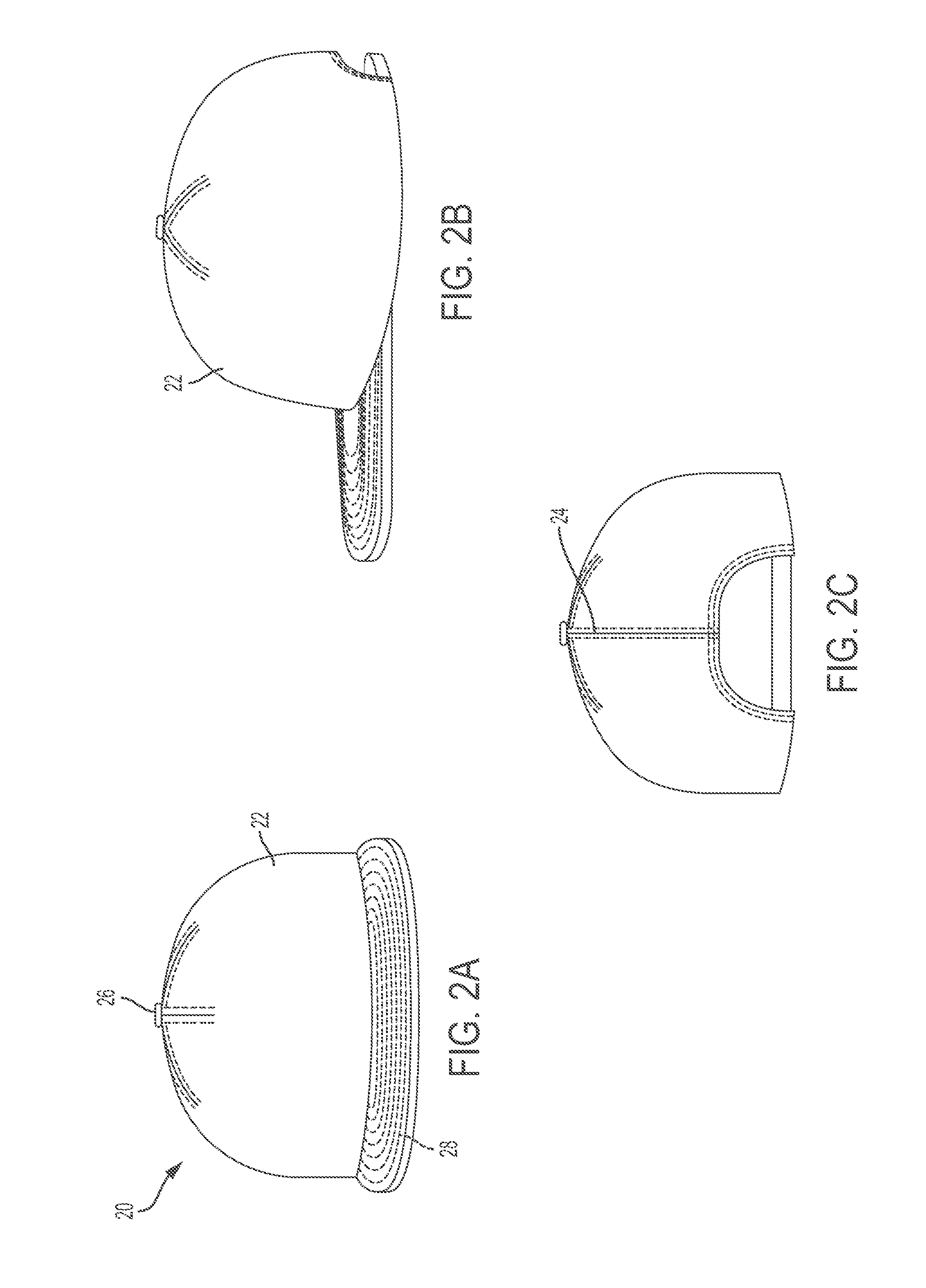
[0006] FIGS. 2A-2E illustrates an exemplary embodiment of a cap having a unique profile. FIG. 2A illustrates a front profile view, FIG. 2B illustrates a first side plan view, FIG. 2C illustrates a back profile view, FIG. 2D illustrates an opposing side plan view, and FIG. 2E illustrates a top plan view of the exemplary embodiment of the cap having a unique profile.
[0007] FIGS. 3A-3E illustrates an exemplary embodiment of a cap having a unique profile. FIG. 3A illustrates a front profile view, FIG. 3B illustrates a first side plan view, FIG. 3C illustrates a back profile view, FIG. 3D illustrates an opposing side plan view, and FIG. 3E illustrates a top plan view of the exemplary embodiment of the cap having a unique profile.
[0008] FIGS. 4A-4E illustrates an exemplary embodiment of a cap having a unique profile. FIG. 4A illustrates a front profile view, FIG. 4B illustrates a first side plan view, FIG. 4C illustrates a back profile view, FIG. 4D illustrates an opposing side plan view, and FIG. 4E illustrates a top plan view of the exemplary embodiment of the cap having a unique profile.
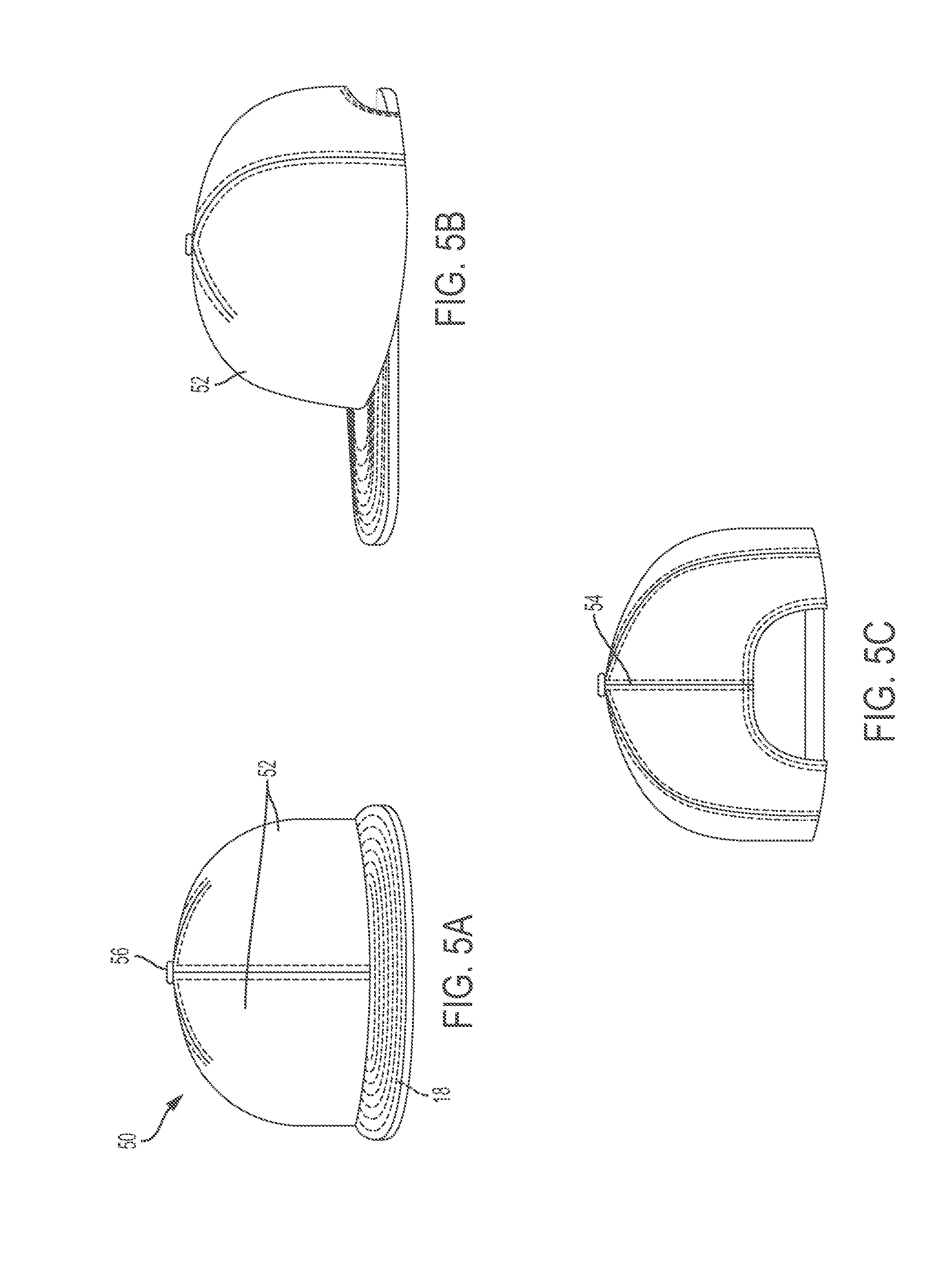
[0009] FIGS. 5A-5E illustrates an exemplary embodiment of a cap having a unique profile. FIG. 5A illustrates a front profile view, FIG. 5B illustrates a first side plan view, FIG. 5C illustrates a back profile view, FIG. 5D illustrates an opposing side plan view, and FIG. 5E illustrates a top plan view of the exemplary embodiment of the cap having a unique profile.
[0010] FIGS. 6A-6E illustrate an exemplary embodiment of a cap having a unique profile. FIG. 6A illustrates a front profile view, FIG. 6B illustrates a first side plan view, FIG. 6C illustrates a back profile view, FIG. 6D illustrates an opposing side plan view, and FIG. 6E illustrates a top plan view of the exemplary embodiment of the cap having a unique profile.
[0011] FIGS. 7A-7D illustrate exemplary fitted mechanisms that may be used in any of the embodiments described herein.
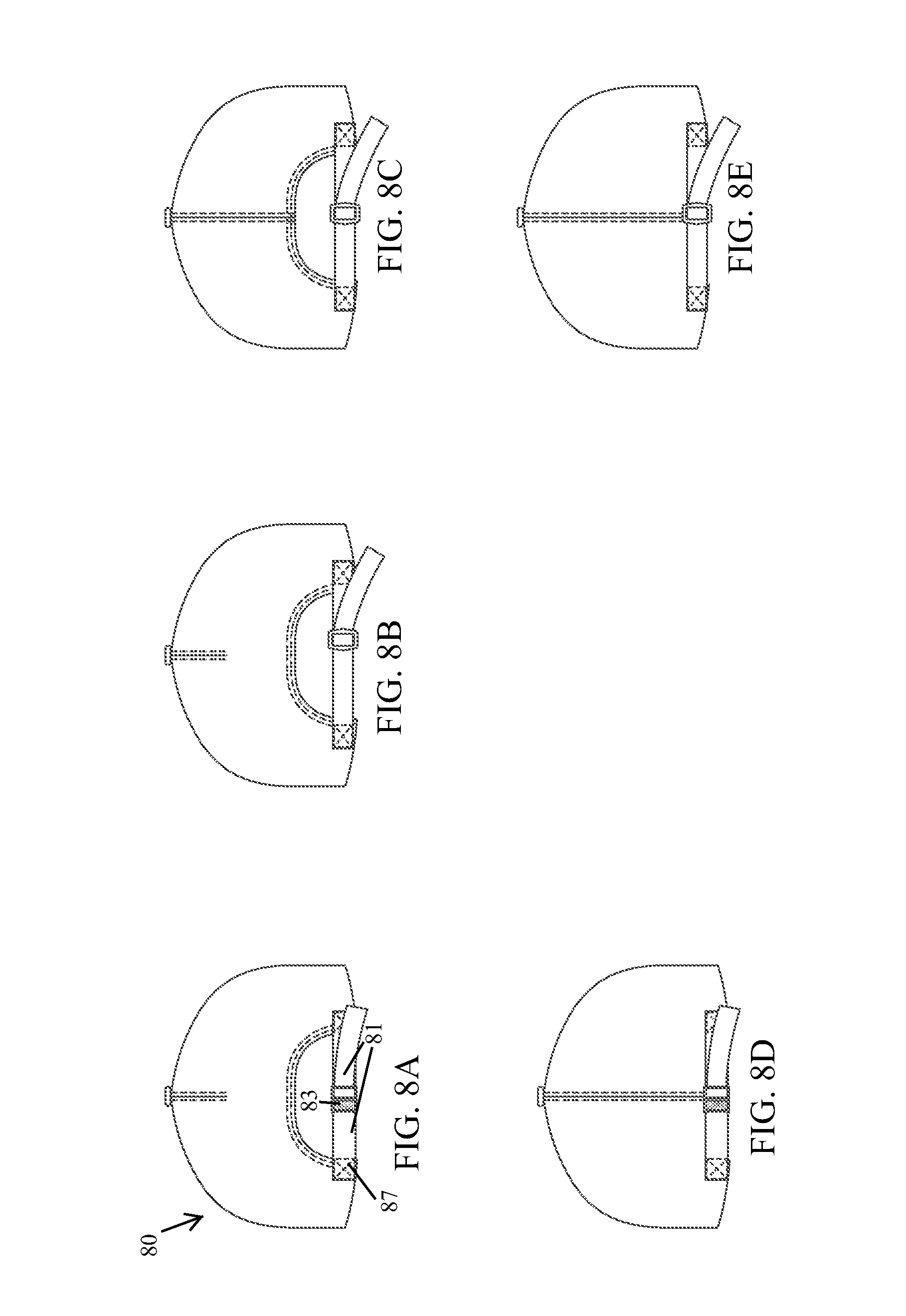
[0012] FIGS. 8A-8E illustrate exemplary fitted mechanisms that may be used in any of the embodiments described herein.
[0013] FIGS. 9A-9C illustrate exemplary fitted mechanisms that may be used in any of the embodiments described herein.
[0014] FIGS. 10A-10G illustrate exemplary fitted mechanisms that may be used in any of the embodiments described herein.
[0015] FIGS. 11A-11B illustrate exemplary fitted mechanisms that may be used in any of the embodiments described herein.
DETAILED DESCRIPTION
[0016] The following detailed description illustrates by way of example, not by way of limitation, the principles of the invention. This description will clearly enable one skilled in the art to make and use the invention, and describes several embodiments, adaptations, variations, alternatives and uses of the invention, including what is presently believed to be the best mode of carrying out the invention. It should be understood that the drawings are diagrammatic and schematic representations of exemplary embodiments of the invention, and are not limiting of the present invention nor are they necessarily drawn to scale.
[0017] Exemplary embodiments described herein include caps having a domed section in which the dome is created by one or more panels and the dome profile is defined by one or more seams and by two or more darts. The combination of seams and darts and their respective strategic position may define novel and unique cap profiles.
[0018] In an exemplary embodiment, a cap may be created by one or more panels of separate material sections coupled together. The one or more panels may include one or more seams between terminal ends of respective panels. The seams may be between adjacent separate panels or between terminal ends of the same panel. The cap may include two or more darts to deform the panels and define a desired profile for the cap. A panel may have no darts, a single dart, two darts, three darts, four darts, or other combination of darts. In an exemplary embodiment, a dart may be positioned between adjacent seams. For example, each panel may include a single dart and each panel coupled to an adjacent panel by a seam. The cap may include two or more darts between adjacent seams. For example, each panel may define two darts and be coupled to an adjacent panel by a seam.
[0019] Different combinations of panels may be used, such that adjacent panels may have the same or a different number of darts as an adjacent panel. In an exemplary embodiment, each panel is the same around the cap. In an exemplary embodiment, two configurations of panels may be used. The different configurations may be alternated between adjacent panels. For example, one configuration of panel may include a dart, while a second configuration of panel may not include a dart. The dart and non-dart panels may alternate around the circumference of the cap. The two configurations of panels may also be positioned adjacent to each other, such that a panel may have a first panel along one adjacent edge that is of the same configuration and a second panel along the other adjacent edge that is of a different configuration. A panel may also have both panels on opposing side where each panel is of the same configuration, while another panel of the cap may be coupled along one or both sides to another panel that is of a different configuration than itself. The pattern of panels including the same or different configurations may be symmetric about the center of the cap from front to back. The pattern of panels including the same or different configurations may be asymmetric about the center of the cap from front to back.
[0020] In an exemplary embodiment, the darts may extend along a length within a panel. The darts of a cap may all be of the same length of may be of different lengths. For example, a dart may extend approximately 1/5, 1/4, 1/3, 1/2, 2/3, 3/4, along the length of a panel between the top of the hat to a bottom exterior, terminal perimeter. A dart may also extend from a bottom exterior, terminal perimeter to the top of the hat, along the length of a panel or upward a partial distance toward the top of the hat. In an exemplary embodiment, the darts converge on a central, top of the dome section of the cap. The darts may meet at the center of the dome portion of the cap. In an exemplary embodiment the darts and seams converge toward the same point. In an exemplary embodiment, the darts terminate before a bottom exterior perimeter of the cap. In an exemplary embodiment, the darts extend from the bottom exterior perimeter of the cap.
[0021] The widths of the respective panels may be the same or different. For example, the panels with more darts may be wider around a circumference of the cap than other panels with fewer or no darts.
[0022] Exemplary embodiments illustrated in FIGS. 2-6 are illustrated with corresponding numbers in common between illustrations. The tens place of the number corresponds to the figure number of the element and the ones place corresponds to the element. For example, each illustrated bill is designated with an "8" in the ones place, and a 2-6 in the tens space depending on whether it is the bill from the FIG. 2 embodiment (i.e. element 28) or the bill from the FIG. 6 embodiment (i.e. element 68). Accordingly, the description of each of the components is understood to be applicable to corresponding components. Therefore, any description of element 26 may equally be applied to any element 36, 46, 56, or 66. Any actual changes between the same element from different embodiments may be understood in the context of the other design changes between the respective exemplary embodiments.
[0023] FIGS. 2A-2E illustrates an exemplary embodiment of a cap having a unique profile. As shown, the unique profile is defined by a single panel 22 creating the dome portion 20 of the cap. Terminal ends of the panel 22 are directly attached by a seam 24 to create a unitary dome made of a single piece of material. A plurality of darts 25 are used to shape and define the profile for the top portion of the cap. The plurality of darts 25 may be more than two darts. The plurality of darts may include three darts, four darts, five darts or more.
[0024] The seam 24 and plurality of darts 25 may converge at a point and extend outwardly away from each other toward an exterior perimeter of the cap. The seam may extend from the point (under a button 26) to the exterior perimeter of the cap. The seam may traverse an entire surface length from the point to the exterior perimeter of the cap. The plurality of darts may extend from the point toward the exterior perimeter. The plurality of darts may terminate before the exterior perimeter of the cap. The plurality of darts may traverse only a partial surface length from the point to the exterior perimeter of the cap.
[0025] As shown in FIG. 2E, the darts and seam may be equidistantly spaced. For example, for a single seam and five darts, adjacent seam/dart or dart/dart may be approximately 60 degrees away. However, distance between adjacent darts and/or seams may be different. For example, adjacent seam to dart or dart to seam may be greater or less than the spacing between an adjacent dart to dart.
[0026] As shown in FIG. 2E, a single seam crosses or interrupts the outer circumferential perimeter of the cap. A profile view of the cap therefore may not include any visual interrupts at the bottom perimeter. Such a configuration may create and define a circular cross section. The cross-section may have a start at a seam, and as the cross-section is circumferentially traversed, the cross-section may be unitary, continuous, and uninterrupted about an entire circumference of the cap. The cross-section may be unitary, continuous, and uninterrupted for approximately a majority (about 50%) of the circumference or more, for approximately 60% or more, for approximately 75% or more. In an exemplary embodiment, the circumference is unitary, continuous, and uninterrupted for a majority of the circumference and only interrupted at a back portion of the cap for a sizing cut out.
[0027] The cap may include embellishments or decorations. For example, the cap may include a cover at the convergence of the seam and darts. In an exemplary embodiment, the cover may be a button 26. However, other components may be used to cover the meeting of the panels defined by the seam and darts, or the convergence may remain visually exposed.
[0028] The cap may include a bill 28 as illustrated. The bill 28 may be generally planar or may be curved. The bill 28 may define an outer curved perimeter. The bill may couple to the exterior perimeter of the dome portion along a portion of the dome portion. The bill may extend outwardly from the dome portion generally perpendicular to a surface of the dome portion. Other bill configurations are also within the scope of the present disclosure. The bill may define an outer curved perimeter. The bill may define other geometric perimeters such as square, rectangular, ovoid, elliptical, and combinations thereof. The outer edge of the bill may define linear, curved, or curvi-linear sections along its length.
[0029] The cap may include a fitted mechanism at the back of the cap. The fitted mechanism may include a system for altering a circumferential length of the cap at the outer perimeter to accommodate various head sizes. The fitted mechanism may be, for example, buttons, buckle, tether, elastic, pull chord, and combinations thereof. Exemplary fitted mechanism is described in more detail with respect to FIGS. 7A-7D, FIGS. 8A-8E, FIGS. 9A-9C, FIGS. 10A-10G, and FIGS. 11A-11B. The cap may not include a fitted mechanism.
[0030] FIGS. 3A-3E illustrates an exemplary embodiment of a cap having a unique profile. The exemplary cap and its unique profile may be defined by only two panels 32. As shown, the exemplary embodiment includes two panels 32 of distinct and separate material directly coupled to form a dome portion 30 of the cap. The two panel configuration includes two seams 34 and a plurality of darts 35. The seams 34 are positioned between respective different panels 32.
[0031] As shown, the seams may align along a width of the cap. The seams may be oriented along any diameter of the cap, such as from front to back, or side to side, or any orientation there between. In an exemplary embodiment, the seams may form a linear projection as seen from a top elevation above the top of the cap. The seams may be positioned approximately 180 degrees from an adjacent seam. The panels may therefore define a first side and a second side and be mirror reflections of the other panel. The sides may be a lateral sides, such as would correspond to the sides of a head of a user. The sides may be forward and backward, such as would correspond to the forehead and back of the head of a user.
[0032] In an exemplary embodiment, the seams do not align. For example, an acute angle may be defined between a first seam and the next adjacent second seam, or an obtuse angle may be defined between a third seam and the next adjacent fourth seam. The angles may be the rotational distance about the circumference of the cap from one seam to the next adjacent seam. The angles may also be seen as the angle between the seam lines when the cap is viewed in elevation from above the top of the cap (such as illustrated in FIG. 3E). For the illustrated two panel configuration, the second seam and third seam may be the same seam and the first and fourth seams may be the same seam. Each of the seams may also be different seams in the case of a different number of panels. The acute angle may be approximately 15 degrees, 20 degrees, 30 degrees, 45 degrees, 60 degrees, 75 degrees, or any degree between 0 and 90. In the case of two panels, the obtuse angle would be the difference of the acute angle from 360 degrees.
[0033] An exemplary cap may include a plurality of darts 35. As shown, the cap may include four darts 35. Each panel 32 may therefore have two darts 35. In an exemplary embodiment, two darts 35 may be positioned between two adjacent seams 34. In this case, as the cap is circumferentially traversed, the combination of seams and darts may look like seam-dart-dart-seam-dart-dart. Each panel 32 may include any number of darts 35. For example, each panel may include three darts, such that three darts are positioned between adjacent seams.
[0034] The positions of the seams and darts may be equidistantly arranged. For example, a seam or dart may be approximately 60 degrees from an adjacent seam or dart for the two seam, four dart configuration.
[0035] In an exemplary embodiment, the dome of the cap may be defined by a combination of six darts and seams. The six darts and seams may be positioned approximately 60 degrees away from an adjacent seam or dart. The six darts and seams may include at least two darts and at least one seam. The darts and seams may include, for example: one seam and five darts, two seams and four darts, three seams and three darts, four seams, and two darts. In an exemplary embodiment, at least one dart may be positioned between two seams.
[0036] In an exemplary embodiment, the dome of the cap may be defined by a combination of five darts and seams. The five darts and seams may be positioned approximately equidistantly away from an adjacent dart or seam, such as approximately 72 degrees away from an adjacent seam or dart. The five darts and seams may also be unequally spaced. For example, one spacing may be approximately 120 degrees while the remaining spacings between adjacent darts and/or seams is approximately 60 degrees. Other spacings may be used in any combination between adjacent darts and seams. For example, a dart may be positioned approximately 15, 30, 45, 50, 60, 72, or 75 degrees away from an adjacent dart or seam.
[0037] FIGS. 4A-4E illustrates an exemplary embodiment of a cap having a unique profile. Exemplary embodiments may define a cap dome profile using only three panels. For example, a cap dome may be created by coupling three, separate and distinct panels together. The coupling between adjacent panels may be at a seam. In an exemplary embodiment, each panel may include a dart. Therefore, the cap profile may be defined by three seams and three darts. A dart may be positioned between adjacent seams. In an exemplary embodiment, the seam/dart configurations are equally spaced. However, any spacing of seams and darts may be used as described herein. As shown the seam dart configuration for an exemplary three panel results in an order of seam-dart-seam-dart-seam-dart. However, one or more of the panels may include two or more darts as well. For example, a seam-dart-dart-seam-dart-seam-dart arrangement may be employed.
[0038] In an exemplary embodiment, a first seam may be aligned with a center of the cap from the center toward the front of the cap. A second and third seam may be positioned extending toward a rear of the cap and off-center from the first seam. As shown, none of the seams may linearly align as viewed from an elevation above the cap.
[0039] In an exemplary embodiment, a seam may align with a dart. The alignment may position the seam and dart within the same plane. A seen from an elevation above the cap, a dart may appear to be a linear extension of a seam. In an exemplary embodiment, each seam may have a corresponding dart extending form a terminal end thereof. In an exemplary embodiment, less each seam may not have a corresponding dart extending from a terminal end thereof.
[0040] FIGS. 5A-5E illustrates an exemplary embodiment of a cap having a unique profile. FIG. 5 illustrates a four panel configuration in which the plurality of panels may include different configurations. As shown, a first panel configuration has a single dart and a second panel configuration includes no darts. The arrangement of the panels may position panels of the same configuration next to each other. For example, a panel may be coupled on one side to first panel of the same configuration and coupled on a second side to a second panel of a different configuration. The panel arrangement may define a pattern of darts and seams for four panels as follows: seam-seam-dart-seam-dart-seam.
[0041] In an exemplary embodiment, the panels are configured such that two darts appear to be extensions of two seams as described herein, and two of the seams appear to be linear extensions of each other. In an exemplary embodiment, a panel of the first configuration traverses a circumferential angle of the cap 120 degrees, while a panel of the second configuration traverse a circumferential angle of the cap 60 degrees. Each panel of the first configuration may include a dart approximately through the center of the panel or positioned approximately 60 degrees from a seam.
[0042] FIGS. 6A-6E illustrates an exemplary embodiment of a cap having a unique profile. FIG. 6 illustrates a four panel configuration in which the plurality of panels may include different configurations. Similar to FIG. 5, the two configurations may include a first configuration having a dart and a second configuration not having a dart. The panels may alternate between the different configurations. For example, as the cap is circumferential traversed, the position of seams and darts may include seam-seam-dart-seam-seam-dart.
[0043] In an exemplary embodiment, two seams may appear to be extensions of each other such that the two seams traverse a diameter across the dome of the cap. As shown, two pairs of seams may define a linear projection across the cap as seen from an elevation above the top of the cap. In an exemplary embodiment, two pairs of seams and define two diameter extensions across the cap dome. The two diameter extensions may cross at a top of the cap dome. The diameter extension may define opposite angles that are approximately the same. The diameter extensions may define a first pair of opposite angles and a second pair of opposite angles. The first pair may or may not be the same angle as the second pair. In an exemplary embodiment, the first pair of angles is approximately 60 degrees, and the second pair of angles is approximately 120 degrees.
[0044] In an exemplary embodiment, adjacent panels may define different widths. For example, a panel of a first configuration may have a smaller width that a panel of a second configuration. The width of the panel of the second configuration may approximate a width of the bill. A panel of the second configuration may be positioned in the front portion of the cap, such that it is configured to cover a user's forehead, when in use. The second configuration may define a panel having one or more darts. The second configuration may define a panel have more darts than the first configuration. The first configuration may not have any darts.
[0045] FIGS. 7A-11B illustrate exemplary fitted mechanisms that may be used in any of the embodiments described herein. The fitted mechanism may include a system for altering a circumferential length of the cap at the outer perimeter to accommodate various head sizes. The fitted mechanism may be, for example, buttons, buckle, tether, elastic, pull chord, and combinations thereof. The fitted mechanism may work in conjunction with a dome portion having a cut out at a back perimeter of the cap. The cut out permits the circumference of the cap to change without buckling or overlapping material around the circumference of the cap. The cut out may define a separation from one side of the cut out to an opposite side of the cut out. In an exemplary embodiment the cut out does not define a separation or gap, such that to reduce the circumference of the cap, a portion of the cap on one side of the cut out overlaps with a portion of the cap on the other side of the cut out.
[0046] FIG. 7A illustrates an exemplary fitted mechanism including a slide buckle. This configuration includes a dome portion 70 having a cut out at a back perimeter of the cap. The cut out permits the circumference of the cap to change without buckling or overlapping material around the circumference of the cap. Each side of the cut out includes a strap 71 coupled thereto. As shown, the straps are coupled through a sewn connection 77. As shown, the straps are positioned on an exterior surface of the cap and then sewn to the cap surface. The sewing can define a decorative pattern. The first strap may be coupled to the second strap by a slide buckle 73. FIG. 7D illustrates a similar exemplary embodiment, where the slide buckle 73 is a buckle.
[0047] FIG. 7B illustrates an exemplary embodiment of a fitted mechanism including a slide buckle. In this case, the fitted mechanism extends across a cut out in the back of the cap. The fitted mechanism includes a first strap coupled to a first side of the cut out and extending across the cut out to the opposing side of the cut out. The first strap is coupled to the first side of the cut out by sewing. The first strap is coupled to the second side of the cut out through a slide buckle.
[0048] FIG. 7C illustrates an exemplary embodiment of a fitted mechanism including a variable length band. The fitted mechanism may extend across a cut out in the back of the cap. The fitted mechanism may include a variable length band such that it can lengthen under an application of a force. In an exemplary embodiment, the fitted mechanism is an elastic band coupled to opposing sides of the cut out.
[0049] FIG. 8A illustrates an exemplary embodiment of a fitted mechanism including a buckle. This configuration includes a dome portion 80 having a cut out at a back perimeter of the cap. Each side of the cut out may include a strap 81 coupled thereto. As shown, the straps may be coupled through a sewn connection 87. As shown, the straps may be positioned on an exterior surface of the cap and then sewn to the cap surface. The stitching can define a decorative pattern. The first strap may be coupled to the second strap by a buckle 83. As shown in FIG. 8A, a dart may not extend to the cut out. FIG. 8B illustrates a similar exemplary embodiment, where the buckle is a slide buckle.
[0050] FIG. 8C illustrates an exemplary embodiment of a fitted mechanism including a slide buckle. The first strap may be coupled to the second strap by the slide buckle. As shown in FIG. 8C, a dart may extend from a portion of the cut out to a top of the dome portion.
[0051] FIG. 8D illustrates an exemplary embodiment of a fitted mechanism including a buckle. As shown in FIG. 8D, this configuration may not have a cut out at a back perimeter of the cap. A dart may extend from a top portion of the variable length band to a top portion of the dome portion. The first strap may be coupled to the second strap by the buckle. FIG. 8E illustrates a similar exemplary embodiment, where the buckle is a slide buckle.
[0052] FIG. 9A illustrates an exemplary embodiment of a fitted mechanism including a band. This configuration may include a dome portion 90 having a cut out at a back perimeter of the cap. The band may be positioned on an exterior surface of the cap, such that a first portion of the band may be located on a first side of the cut out and a second portion of the band may be located on a second side of the cut out. The band may be flexible or elastic, such that the band may allow a circumference of the cap to change. The band may be ribbed. As shown in FIG. 9A, a dart may extend from a top portion of the band to a top of the dome portion. FIG. 9B illustrates a similar exemplary embodiment, where the band is approximately the same size of the cut out. FIG. 9C illustrates a similar exemplary embodiment, where the dart does not extend to the cut out. As shown in the comparison between FIGS. 9B and 9C, the cut out may include any shape. As seen in FIG. 9B, the cut out may be semi-ovoid or rounded-rectangular, or, as seen in FIG. 9C, the cut out may be triangular. The cut out may also be rectangular, square, curvy, curvy-linear, or other combinations or geometric and non-geometric shapes.
[0053] FIG. 10A illustrates an exemplary embodiment of a fitted mechanism including a pull member. This configuration may include a dome portion 100 having a panel 103 at a back perimeter of the cap. The pull member 101 may extend from the panel 103. The pull member 101 may permit a circumference of the cap to change. A sizer 105 may be used to prevent the pull member from moving further. The sizer may slide along the pull member 101. For example, the pull member 101 may be pulled away from the panel 103 in order to reduce the circumference of the cap. Once the circumference is of a desired dimension, the sizer 105 may be slid towards the panel in order to prevent the circumference from further changing.
[0054] FIG. 10B illustrates an exemplary embodiment of a fitted mechanism including a slide buckle. As shown in FIG. 10B, a strap 107 may wrap around a circumference of the cap.
[0055] FIG. 10C illustrates an exemplary embodiment of a fitted mechanism including a drawstring. This configuration may include a dome portion having a cut out 109 at a back perimeter of the cap. Each side of the cut out may include a portion of the drawstring 111 coupled thereto. As shown, the drawstring may be coupled to the cap through eyelets 113. The terminal ends of the drawstring may be left free. The terminal ends of the drawstring may be tied together in order to fix a circumference of the cap at a desired dimension. FIG. 10E illustrates a similar exemplary embodiment where the drawstring is laced through multiple eyelets.
[0056] FIG. 10D illustrates a similar exemplary embodiment to FIG. 10C where the drawstring is a loop and has no terminal ends. As shown in FIG. 10D, the drawstring may traverse a width of the cut out multiple times, passing through at least one eyelet on each traversal.
[0057] FIG. 10F illustrates an exemplary embodiment of a fitted mechanism including a loop. A first portion of the loop 120 may couple with a first portion of the cut out and a second portion of the loop 122 may couple with a second portion of the cut out. The first portion of the loop 120 may be secured by a first sizer 124 and the second portion of the loop 122 may be secured by a second sizer 126. The first and second sizers may prevent the loop from moving. The first and second sizers may slideably move along the first and second portions of the loop. For example, the first portion of the loop may be pulled away from the cap in order to reduce the circumference of the cap. Once the circumference is of a desired dimension, the first sizer may be slid towards the panel in order to prevent the circumference from further changing.
[0058] FIG. 10G illustrates an exemplary embodiment of a fitted mechanism including a band. As shown in FIG. 10G, the band 150 may extend along a bottom portion of the cap. The band may extend from a first section of the bottom portion to a second section of the bottom portion. The band may be flexible or elastic, such that the band may allow a circumference of the cap to change. The band may be ribbed.
[0059] FIG. 11A illustrates an exemplary embodiment of a fitted mechanism including a hook mechanism. This configuration includes a dome portion 200 having a cut out at a back perimeter of the cap. A first side of the cut out may include a first strap 201 and a second side of the cut out may include a second strap 203. The first strap may include a hook 205. The second strap may include a ring 207. The hook 205 may couple with the ring 207. The first and second straps may be coupled to the cap through a sewn connection. The sewn connection can define a decorative pattern. As shown in FIG. 11A, a dart may extend from a top portion of the cut out to a top portion of the dome portion. FIG. 11B illustrates a similar exemplary embodiment, where the dart may not extend to the cut out.
[0060] Although embodiments of this invention have been fully described with reference to the accompanying drawings, it is to be noted that various changes and modifications will become apparent to those skilled in the art. Such changes and modifications are to be understood as being included within the scope of embodiments of this invention as defined by the appended claims. Specifically, exemplary components are described herein. Any combination of these components may be used in any combination. For example, any component, such as any dart, seam, or closure arrangement may be added, duplication, removed, or used in any combination and remain within the scope of the present disclosure. Embodiments are exemplary only, and provide an illustrative combination of features, but are not limited thereto.
[0061] Exemplary embodiments may be described in terms of a seam. The seam may be a coupling of one panel to another panel. For example, seam may be at a terminal end of a material section to another terminal end of a material section along a length. The material section may be the same material section or may be different material sections defined by separate panels. The terminal end may be an end of a material section defining an exterior perimeter of the section. The terminal end may be distinguished from an end of a material section. For example, an end may be created within a material section by partially cutting a material section forming two ends within an interior portion of the material. The exterior perimeter may define terminal ends, while the cut through the interior may be considered an end of the material. The seam may extend along an entire length or side of a panel. The seam may also extend all of the way to a perimeter or terminal edge of the cap. For example, a seam may extend along an edge of a panel along a length from the top of the cap to the bottom perimeter of the cap. As shown by, for example, FIGS. 2A-2E, a seam may couple one panel to itself. As shown by, for example, FIGS. 3A-2E, a seam may also couple one panel to a different, separate panel, such that two separate material sections are coupled by the seam.
[0062] Exemplary embodiments may be described in terms of a dart. A dart may be a coupling of material sections along a length. The dart may couple different portions of the same material section together. Therefore, a dart or different combinations of darts in strategic positions may be used to deform the material and define unique cap profiles. A dart, for example, may couple interior ends of a material section together, where an interior end is created by a cut in the interior of a material section. A dart may therefore extend from a terminal end of the material section to an interior region of the material section. The end of the dart may therefore terminate at a material. The dart may be created through a pleat or a cut and attachment of different material sections.
[0063] When used in this specification and claims, the terms "comprises" and "comprising" and variations thereof mean that the specified features, steps or integers are included. The terms are not to be interpreted to exclude the presence of other features, steps or components.
[0064] The features disclosed in the foregoing description, or the following claims, or the accompanying drawings, expressed in their specific forms or in terms of a means for performing the disclosed function, or a method or process for attaining the disclosed result, as appropriate, may, separately, or in any combination of such features, be utilised for realising the invention in diverse forms thereof.
* * * * *
D00000
D00001
D00002
D00003
D00004
D00005
D00006
D00007
D00008
D00009
D00010
D00011
D00012

D00013
D00014

D00015

D00016

D00017

D00018

D00019

XML
uspto.report is an independent third-party trademark research tool that is not affiliated, endorsed, or sponsored by the United States Patent and Trademark Office (USPTO) or any other governmental organization. The information provided by uspto.report is based on publicly available data at the time of writing and is intended for informational purposes only.
While we strive to provide accurate and up-to-date information, we do not guarantee the accuracy, completeness, reliability, or suitability of the information displayed on this site. The use of this site is at your own risk. Any reliance you place on such information is therefore strictly at your own risk.
All official trademark data, including owner information, should be verified by visiting the official USPTO website at www.uspto.gov. This site is not intended to replace professional legal advice and should not be used as a substitute for consulting with a legal professional who is knowledgeable about trademark law.