Power Tool
Dedrickson; Ryan A. ; et al.
U.S. patent application number 16/252757 was filed with the patent office on 2019-07-25 for power tool. The applicant listed for this patent is MILWAUKEE ELECTRIC TOOL CORPORATION. Invention is credited to Ryan A. Dedrickson, Ian Duncan, Timothy R. Reichert.
| Application Number | 20190229579 16/252757 |
| Document ID | / |
| Family ID | 65138829 |
| Filed Date | 2019-07-25 |


| United States Patent Application | 20190229579 |
| Kind Code | A1 |
| Dedrickson; Ryan A. ; et al. | July 25, 2019 |
POWER TOOL
Abstract
A power tool includes an electric motor having an output shaft, a transmission having a transmission housing, a spindle rotatable in response to receiving torque from the transmission and a pinion coupled to the output shaft. The pinion includes a bushing portion, a toothed portion for driving the transmission, and a cylindrical portion between the bushing portion and the toothed portion. The power tool further comprises a fan coupled to the bushing portion of the pinion and a bearing arranged between the cylindrical portion and the transmission housing for rotatably supporting the pinion and the output shaft.
| Inventors: | Dedrickson; Ryan A.; (Sussex, WI) ; Duncan; Ian; (Milwaukee, WI) ; Reichert; Timothy R.; (Franklin, WI) | ||||||||||
| Applicant: |
|
||||||||||
|---|---|---|---|---|---|---|---|---|---|---|---|
| Family ID: | 65138829 | ||||||||||
| Appl. No.: | 16/252757 | ||||||||||
| Filed: | January 21, 2019 |
Related U.S. Patent Documents
| Application Number | Filing Date | Patent Number | ||
|---|---|---|---|---|
| 62620542 | Jan 23, 2018 | |||
| Current U.S. Class: | 1/1 |
| Current CPC Class: | H02K 7/003 20130101; F16H 57/08 20130101; F16C 19/06 20130101; F16H 1/28 20130101; B25F 5/001 20130101; B25F 5/008 20130101; F16D 2001/103 20130101; F16H 57/0416 20130101; H02K 7/14 20130101; F16H 57/0495 20130101; H02K 7/145 20130101; H02K 9/04 20130101; F16D 1/101 20130101; H02K 9/06 20130101; H02K 7/116 20130101; F16C 2380/27 20130101 |
| International Class: | H02K 7/14 20060101 H02K007/14; F16D 1/10 20060101 F16D001/10; F16H 1/28 20060101 F16H001/28; F16H 57/08 20060101 F16H057/08; H02K 9/04 20060101 H02K009/04; F16C 19/06 20060101 F16C019/06 |
Claims
1. A power tool comprising: an electric motor including an output shaft; a transmission including a transmission housing; a spindle rotatable in response to receiving torque from the transmission; a pinion coupled to the output shaft, the pinion including a bushing portion, a toothed portion for driving the transmission, and a cylindrical portion between the bushing portion and the toothed portion; a fan coupled to the bushing portion of the pinion; and a bearing arranged between the cylindrical portion and the transmission housing for rotatably supporting the pinion and the output shaft.
2. The power tool of claim 1, wherein the bearing includes an inner race that is coupled to the cylindrical portion and an outer race that is coupled to the transmission housing.
3. The power tool of claim 2, wherein the inner race is press-fit or interference-fit to the cylindrical portion of the pinion.
4. The power tool of claim 2, wherein the outer race is slip-fit to the transmission housing.
5. The power tool of claim 2, further comprising a plurality of rollers between the inner race and the outer race.
6. The power tool of claim 1, wherein the bushing portion includes splines, and wherein the fan includes corresponding splines that engage the splines of the bushing portion.
7. The power tool of claim 1, wherein the transmission is a planetary transmission having a plurality of planet gears.
8. The power tool of claim 7, wherein the transmission housing includes an opening through which the toothed portion of the pinion extends, and wherein the toothed portion of the pinion is configured as a sun gear that meshes with the planet gears.
9. The power tool of claim 8, wherein the transmission housing defines a recess in which the bearing is arranged, and wherein the recess is adjacent the opening.
10. The power tool of claim 1, wherein the pinion is press-fit or interference-fit to the output shaft.
11. The power tool of claim 1, wherein the pinion is integrally formed with the output shaft.
12. A power tool comprising: an electric motor including an output shaft; a transmission including a transmission housing; a spindle rotatable in response to receiving torque from the transmission; a pinion coupled to the output shaft, the pinion including a bushing portion including splines, a toothed portion for driving the transmission, and a cylindrical portion between the bushing portion and the toothed portion; a fan including corresponding splines that couple the fan to the splines of the bushing portion, such that the fan is coupled for co-rotation with the bushing portion; and a bearing rotatably supporting the pinion and the output shaft, the bearing including an inner race coupled to the cylindrical portion of the pinion, an outer race coupled to the transmission housing, and a plurality of rollers between the inner race and the outer race.
13. The power tool of claim 12, wherein the inner race is press-fit or interference-fit to the cylindrical portion of the pinion.
14. The power tool of claim 12, wherein the outer race is slip-fit to the transmission housing.
15. The power tool of claim 12, wherein the transmission is a planetary transmission having a plurality of planet gears.
16. The power tool of claim 15, wherein the transmission housing includes an opening through which the toothed portion of the pinion extends, and wherein the toothed portion of the pinion is configured as a sun gear that meshes with the planet gears.
17. The power tool of claim 16, wherein the transmission housing defines a recess in which the bearing is arranged, and wherein the recess is adjacent the opening.
18. The power tool of claim 12, wherein the pinion is press-fit or interference-fit to the output shaft.
19. The power tool of claim 12, wherein the pinion is integrally formed with the output shaft.
20. A power tool comprising: an electric motor including an output shaft; a transmission including a transmission housing and a plurality of planet gears; a spindle rotatable in response to receiving torque from the transmission; a pinion coupled to the output shaft, the pinion including a bushing portion including splines, a toothed portion extending through an opening in the transmission housing and meshed with the planet gears in the transmission housing, and a cylindrical portion between the bushing portion and the toothed portion; a fan including corresponding splines that couple the fan to the splines of the bushing portion, such that the fan is coupled for co-rotation with the bushing portion; and a bearing rotatably supporting the pinion and the output shaft, the bearing including an inner race coupled to the cylindrical portion of the pinion, an outer race positioned within a recess in the transmission housing adjacent the opening, and a plurality of rollers between the inner race and the outer race.
Description
CROSS-REFERENCE TO RELATED APPLICATIONS
[0001] This application claims priority to co-pending U.S. Provisional Patent Application No. 62/620,542 filed on Jan. 23, 2018, the entire content of which is incorporated herein by reference.
FIELD OF THE INVENTION
[0002] The present invention relates to power tools, and more particularly to power tool drive assemblies.
BACKGROUND OF THE INVENTION
[0003] Power tools include electric motors having an output shaft to which a pinion is attached to transfer torque from the motor to a transmission. Fans are sometimes rotatably coupled to the output shaft to cool the motor as the output shaft rotates.
SUMMARY OF THE INVENTION
[0004] The present invention provides, in one aspect, a power tool comprising an electric motor including an output shaft, a transmission including a transmission housing, a spindle rotatable in response to receiving torque from the transmission, and a pinion coupled to the output shaft. The pinion includes a bushing portion, a toothed portion for driving the transmission, and a cylindrical portion between the bushing portion and the toothed portion. The rotary power tool also includes a fan coupled to the bushing portion of the pinion and a bearing arranged between the cylindrical portion and the transmission housing for rotatably supporting the pinion and the output shaft.
[0005] The present invention provides, in another aspect, a power tool comprising an electric motor including an output shaft, a transmission including a transmission housing, a spindle rotatable in response to receiving torque from the transmission, and a pinion coupled to the output shaft. The pinion includes a bushing portion including splines, a toothed portion for driving the transmission, and a cylindrical portion between the bushing portion and the toothed portion. The power tool further comprises a fan including corresponding splines that couple the fan to the splines of the bushing portion, such that the fan is coupled for co-rotation with the bushing portion. The power tool further comprises a bearing rotatably supporting the pinion and the output shaft. The bearing includes an inner race coupled to the cylindrical portion of the pinion, an outer race coupled to the transmission housing, and a plurality of rollers between the inner race and the outer race.
[0006] The present invention provides, in yet another aspect, a power tool comprising an electric motor including an output shaft, a transmission including a transmission housing and a plurality of planet gears, a spindle rotatable in response to receiving torque from the transmission, and a pinion coupled to the output shaft. The pinion includes a bushing portion including splines, a toothed portion extending through an opening in the transmission housing and meshed with the planet gears in the transmission housing, and a cylindrical portion between the bushing portion and the toothed portion. The power tool further comprises a fan including corresponding splines that couple the fan to the splines of the bushing portion, such that the fan is coupled for co-rotation with the bushing portion. The power tool also comprises a bearing rotatably supporting the pinion and the output shaft. The bearing includes an inner race coupled to the cylindrical portion of the pinion, an outer race positioned within a recess in the transmission housing adjacent the opening, and a plurality of rollers between the inner race and the outer race.
[0007] Other features and aspects of the invention will become apparent by consideration of the following detailed description and accompanying drawings.
BRIEF DESCRIPTION OF THE DRAWINGS
[0008] FIG. 1 is a schematic view of a power tool in accordance with an embodiment of the invention.
[0009] FIG. 2 is an enlarged cross-sectional view of the power tool of FIG. 1.
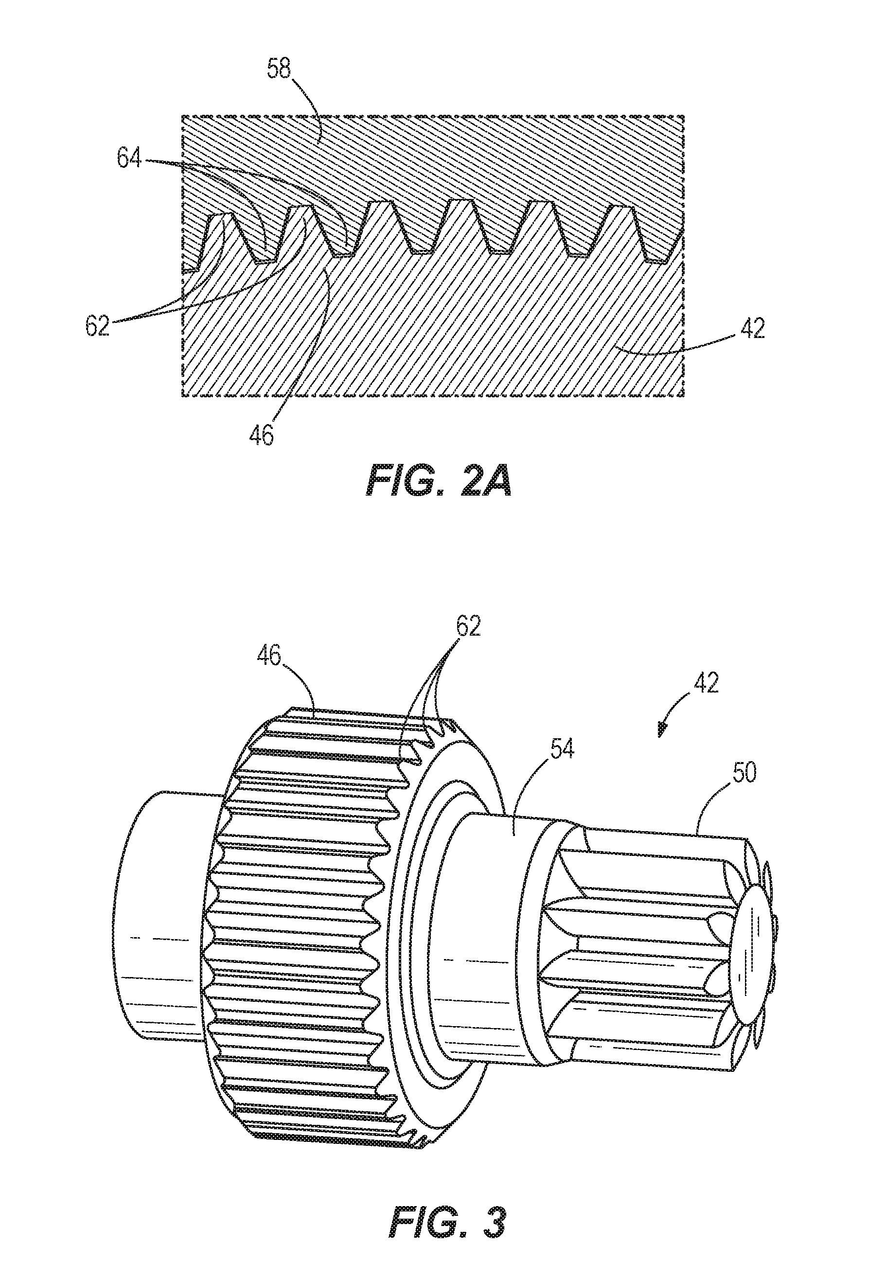
[0010] FIG. 2A is an enlarged plan view of the power tool along line 2A-2A in FIG. 2.
[0011] FIG. 3 is a perspective view of a pinion of the power tool of FIG. 1.
[0012] FIG. 4 is an enlarged cross-sectional view of the power tool of FIG. 1, according to another embodiment of the invention.
[0013] Before any embodiments of the invention are explained in detail, it is to be understood that the invention is not limited in its application to the details of construction and the arrangement of components set forth in the following description or illustrated in the following drawings. The invention is capable of other embodiments and of being practiced or of being carried out in various ways. Also, it is to be understood that the phraseology and terminology used herein is for the purpose of description and should not be regarded as limiting.
DETAILED DESCRIPTION
[0014] As shown schematically in FIG. 1, a power tool, such as a rotary power tool 10, includes a housing 14, a trigger 16 on the housing 14, an electric motor 18, a multi-stage planetary transmission 22, and a spindle 24 that receives torque from the motor 18 via the transmission 22 when an operator presses the trigger 16. As shown in FIG. 2, the motor 18 includes a stator 26 and a rotor 30. In the illustrated embodiment, the rotor 30 includes a motor output shaft 34 extending from the stator 26 and a pinion 42 is coupled for co-rotation with the motor output shaft 34 (e.g., by an interference fit, a press-fit, etc.). In other embodiments such as the one shown in FIG. 4, the pinion 42 is integrally formed with the output shaft 34. As shown in FIGS. 2 and 3, the pinion 42 includes a bushing portion 46, a toothed portion 50, and a cylindrical portion 54 between the bushing portion 46 and the toothed portion 50. The bushing portion 46 is configured to rotatably couple a fan 58 having blades 60 to the pinion 42. In the illustrated embodiment, the bushing portion 46 includes splines 62 and the fan 58 includes corresponding splines 64 that engage the splines 62 of the bushing portion 46 as shown in FIG. 2A, thereby ensuring co-rotation of the fan 58 and the pinion 42. The toothed portion 50 is configured as a sun gear that is meshed with multiple planet gears 66 of the multi-stage planetary transmission 22. The transmission 22 includes a transmission housing 70 that has an opening 74 through which the toothed portion 50 of the pinion 42 extends.
[0015] On a side of the transmission housing 70 facing the motor 18, the transmission housing 70 defines a recess 78 for receiving a bearing 82 having an inner race 86, an outer race 90, and a plurality of rollers 94 between the inner and outer races 86, 90. The bearing 82 is arranged on the cylindrical portion 54 of the pinion 42 for rotatably supporting the pinion 42 and the output shaft 34 on the transmission housing 70, which in turn is supported by the power tool housing 14. In some embodiments, the inner race 86 is interference or press-fit to the cylindrical portion 54 and the outer race 90 is slip-fit to the transmission housing 70 within the recess 78.
[0016] In operation, an operator presses the trigger 16 of the power tool 10, which activates the motor 18 and causes the output shaft 34 and the pinion 42 to rotate. The fan 58 is also caused to rotate via its connection with the bushing portion 46, resulting in the blades 60 creating a cooling airflow through the motor 18. As the pinion 42 rotates, the rotating toothed portion 50 drives the planet gears of the transmission 22, ultimately causing the spindle 24 to rotate in response to receiving torque from the transmission 22.
[0017] Various features of the invention are set forth in the following claims.
* * * * *
D00000
D00001
D00002
D00003
XML
uspto.report is an independent third-party trademark research tool that is not affiliated, endorsed, or sponsored by the United States Patent and Trademark Office (USPTO) or any other governmental organization. The information provided by uspto.report is based on publicly available data at the time of writing and is intended for informational purposes only.
While we strive to provide accurate and up-to-date information, we do not guarantee the accuracy, completeness, reliability, or suitability of the information displayed on this site. The use of this site is at your own risk. Any reliance you place on such information is therefore strictly at your own risk.
All official trademark data, including owner information, should be verified by visiting the official USPTO website at www.uspto.gov. This site is not intended to replace professional legal advice and should not be used as a substitute for consulting with a legal professional who is knowledgeable about trademark law.