Muzzleloader Systems
Peterson; Bryan P. ; et al.
U.S. patent application number 16/254561 was filed with the patent office on 2019-07-25 for muzzleloader systems. The applicant listed for this patent is Vista Outdoor Operations LLC. Invention is credited to Erik K. Carlson, David M. Laska, Adam J. Moser, Bryan P. Peterson, Matthew S. Schroeder.
| Application Number | 20190226818 16/254561 |
| Document ID | / |
| Family ID | 67299257 |
| Filed Date | 2019-07-25 |


| United States Patent Application | 20190226818 |
| Kind Code | A1 |
| Peterson; Bryan P. ; et al. | July 25, 2019 |
MUZZLELOADER SYSTEMS
Abstract
Muzzleloader systems include a pre-packaged propellant charge with a primer receptacle for providing efficient loading and unloading of the muzzleloader. The muzzleloader accepts in the breech end a propellant containment vessel that abuts against a constriction portion with a reduced diameter portion. The propellant containment vessel having an end portion with a tapered surface that conforms to the constriction portion surface. A projectile is inserted in the muzzle end of the muzzleloader and seats against the constriction portion.
| Inventors: | Peterson; Bryan P.; (Isanti, MN) ; Laska; David M.; (Andover, MN) ; Schroeder; Matthew S.; (Princeton, MN) ; Moser; Adam J.; (Big Lake, MN) ; Carlson; Erik K.; (Oak Grove, MN) | ||||||||||
| Applicant: |
|
||||||||||
|---|---|---|---|---|---|---|---|---|---|---|---|
| Family ID: | 67299257 | ||||||||||
| Appl. No.: | 16/254561 | ||||||||||
| Filed: | January 22, 2019 |
Related U.S. Patent Documents
| Application Number | Filing Date | Patent Number | ||
|---|---|---|---|---|
| 62794602 | Jan 19, 2019 | |||
| 62619851 | Jan 21, 2018 | |||
| Current U.S. Class: | 1/1 |
| Current CPC Class: | F41C 9/08 20130101; F42B 5/38 20130101 |
| International Class: | F42B 5/38 20060101 F42B005/38; F41C 9/08 20060101 F41C009/08 |
Claims
1. A muzzleloader system comprising muzzleloader, a polymer propellant vessel with propellant hermetically sealed therein, a projectile and a primer; the muzzleloader comprising a stock, a receiver and a barrel, the barrel having a breech portion, a muzzle portion, and a barrel bore with a barrel axis, the muzzleloader openable exposing a breech face and a propellant containment vessel chamber opening at the breech face, the propellant containment vessel chamber extending at least 2.5 inches inwardly from the breech face, the propellant containment vessel chamber having a annular flange recess at the breech face extending axially inwardly at least 0.08 inches, the barrel having a constriction portion at a forward end of the propellant containment vessel chamber, and a projectile receiving region forward of the constriction portion; the propellant containment vessel being entirely formed of polymer and filled with the propellant, the propellant containment vessel being elongate with a central axis and having a conforming shape to the propellant containment vessel chamber and having a closed polymer head portion, a closed forward portion, and an intermediate portion extending therebetween, the closed polymer head portion having a centrally located primer receptacle, without a primer therein, and a flange extending therearound, the flange having an exterior cylindrical surface with an axial length of at least 0.08 inches, the intermediate portion having conical side wall with a conical surface, the closed polymer forward portion with an end wall and a conforming shape to the constriction portion, the propellant containment vessel having a length to maximum diameter of the flange of at least 4:1; the projectile being sized to the barrel bore; and the primer being sized for the receptacle.
2. The muzzleloader system of claim 1, wherein the tapering conical sidewall has a taper of at least 0.4 degrees.
3. The muzzleloader system of claim 1, wherein the propellant containment vessel comprises polyethylene.
4. The muzzleloader system of claim 1, wherein the closed polymer head portion has a unitary webbing portion at a bottom of a primer recess in the primer receptacle.
5. The muzzleloader system of claim 1, wherein the closed polymer head portion has is sealed by a manually removable closure at the primer recess.
6. The muzzleloader system of claim 1 wherein the closed forward portion has an end wall and a unitary skirt extending therefrom, the skirt underlaying the tapering conical wall portion and joined thereto at an interface.
7. The muzzleloader system of claim 6, wherein the interface is breechable upon ignition of the propellant firing the projectile, whereby when the muzzleloader is fired, the end wall and unitary skirt pass through the constriction portion and are ejected from the muzzleloader immediately behind the projectile.
8. The muzzleloader system of claim 7, wherein the end wall and unitary skirt deform as they pass through the constriction portion.
9. The muzzleloader system of claim 7, wherein the end wall and unitary skirt have a maximum diameter of less than the minimal inside diameter of the constriction portion.
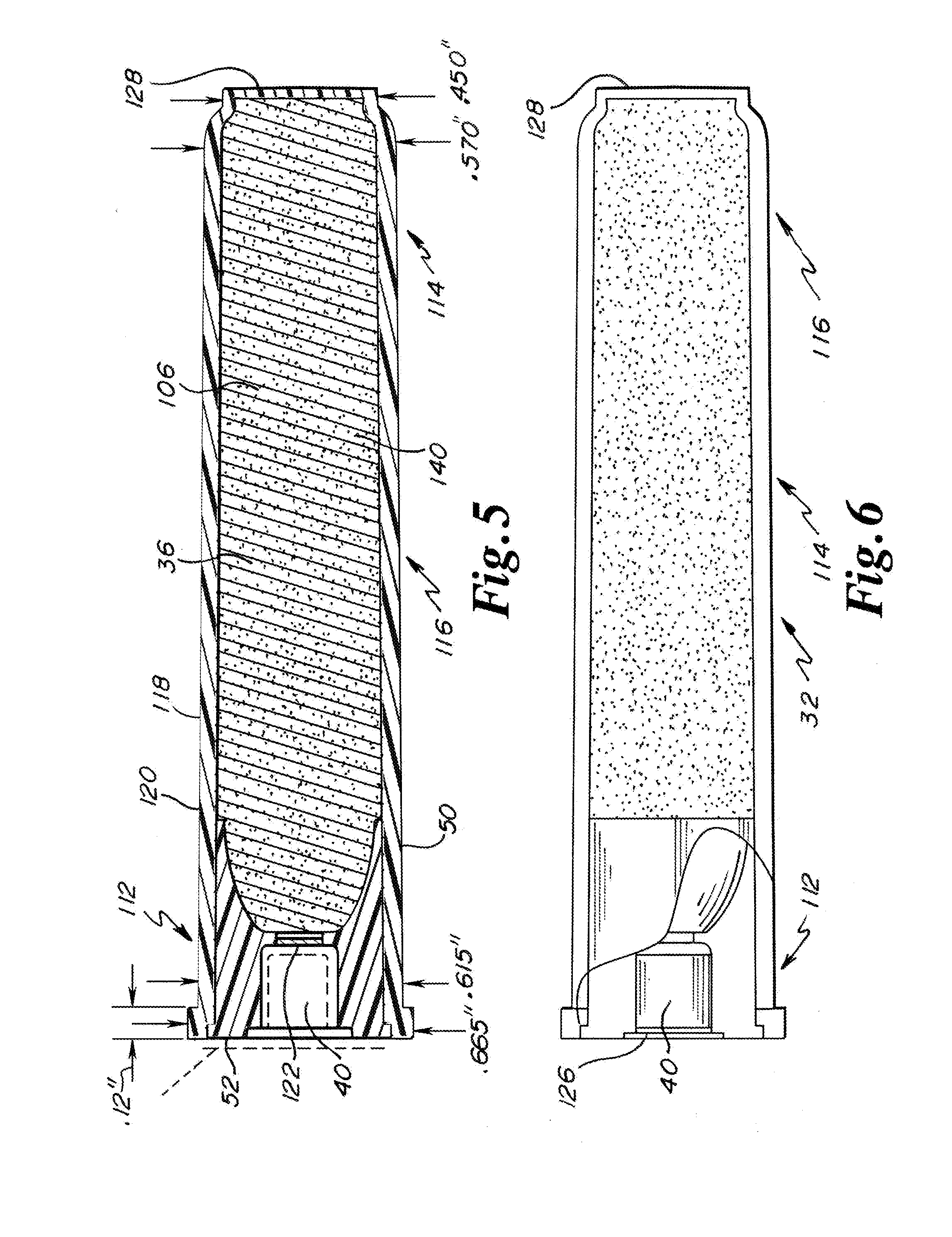
10. A muzzleloader propellant containment vessel for use with a primer, a projectile and a muzzleloader, the muzzleloader having a barrel with a propellant containment vessel chamber open rearwardly, a constriction portion forward of the propellant containment vessel chamber, and a projectile receiving region forward of the constriction portion, the projectile being receivable in the barrel bore at a muzzle end, the muzzleloader power cell comprising: the muzzleloader propellant containment vessel hermetically sealed and filled with propellant, the propellant containment vessel being elongate with a central axis and having a conforming shape to the propellant containment vessel chamber and having a closed polymer head portion, a closed forward portion, and an intermediate portion extending therebetween, the closed polymer head portion having a centrally located primer receptacle, without a primer therein, and a flange extending therearound, the flange having an exterior cylindrical surface with an axial length of at least 0.08 inches, the intermediate portion being tubular and having a conical side wall with a conical surface, the closed polymer forward portion with an end wall and a conforming shape to the constriction portion, the propellant containment vessel having a length to maximum diameter of the flange of at least 4:1.
11. The muzzleloader system of claim 10, wherein the propellant containment vessel defines a cavity having a volume between 0.40 and 0.50 cubic inches.
12. The muzzleloader system of claim 10, wherein the propellant containment vessel is entirely polymeric and comprises polyethylene.
13. The muzzleloader system of claim 10, wherein the closed polymer head portion has a unitary webbing portion at a bottom of a primer recess in the primer receptacle.
14. The muzzleloader system of claim 10, wherein the closed polymer head portion has is sealed by a manually removable closure at the primer recess.
15. The muzzleloader system of claim 10, wherein the closed forward portion has an end wall and a unitary skirt extending therefrom, the skirt underlaying the tapering conical wall portion and joined thereto at an interface.
16. The muzzleloader system of claim 10, wherein the closed head portion is underlaying the tubular intermediate portion.
17. A method of using a muzzleloader of a muzzleloader system, the system comprising muzzleloader, a polymer propellant vessel with propellant hermetically sealed therein, a projectile and a primer; the muzzleloader comprising a stock, a receiver and a barrel, the barrel having a breech portion, a muzzle portion, and a barrel bore with a barrel axis, the muzzleloader openable exposing a breech face and a propellant containment vessel chamber opening at the breech face, the propellant containment vessel chamber having a annular flange recess at the breech face, the barrel having a constriction portion at a forward end of the propellant containment vessel chamber, and a projectile receiving region forward of the constriction portion; the propellant containment vessel formed of polymer, the propellant containment vessel being elongate with a central axis and having a conforming shape to the propellant containment vessel chamber and having a closed polymer head portion, a closed forward portion, and an intermediate portion extending therebetween, the closed polymer head portion having a centrally located primer receptacle, without a primer therein, and a flange extending therearound, the intermediate portion having a tubular side wall, the closed polymer forward portion with an end wall and a conforming shape to the constriction portion; the method comprising: inserting the projectile in the muzzle end of the barrel and seating the projectile in the projectile seating region; opening the breech portion of the muzzleloader; inserting the propellant containment vessel with propellant into the propellant containment vessel chamber; inserting the primer in the propellant containment vessel after the propellant containment vessel is in the propellant containment vessel chamber; closing the breech portion of the muzzleloader.
18. The method of using a muzzleloader of a muzzleloader system of claim 17, further comprising actuating a trigger mechanism whereby a firing pin strikes a primer and expanding gases from the primer enter the propellant containment vessel igniting the propellant therein.
19. The method of using a muzzleloader of a muzzleloader system of claim 17, further comprising opening a seal at the primer receptacle when inserting the primer.
20. The method of using a muzzleloader of a muzzleloader system of claim 17, further comprising emptying the muzzleloader without firing the muzzleloader, by opening the breech portion of the muzzleloader, removing the unfired propellant containment vessel, pushing the projectile from the projectile seating region and out of the muzzle end of the barrel, and closing the breech portion.
Description
FIELD OF THE INVENTION
[0001] The present invention is directed to a system for muzzleloaders for improving safety, reliability, and performance.
BACKGROUND OF THE INVENTION
[0002] Muzzleloaders are a class of firearms in which the propellant charge and bullet are separately loaded into the barrel immediately prior to firing. Unlike modern breech loaded firearms where the bullet, propellant charge and primer are loaded as prepackaged cartridges, muzzleloaders are loaded by feeding a propellant charge through the muzzle of the barrel before ramming a bullet down the barrel with a ramrod until the bullet is seated against the propellant charge at the breech end of the barrel. A primer is inserted at the breech to be in communication with the propellant. The primer is then struck by an inline firing pin or an external hammer to ignite the propellant charge to create propellant gases for propelling the bullet.
[0003] A variability in muzzleloaders not present in cartridge based firearms is the quantity and type of the propellant charge. Unlike cartridge firearms where a cartridge is preloaded with a bullet and premeasured quantity of propellant is loaded into the firearm for firing, the bullet and propellant charge are combined within the firearm for firing. Accordingly, the muzzleloader operator can select the optimal bullet, propellant type and quantity combination for each shot, which is particularly advantageous given the long reloading time for muzzleloaders. While the variability of the bullet--propellant charge combination allows for an optimized shot, varying the bullet and in particular the propellant and quantity of propellant can significantly change the appropriate seating depth of the bullet. With loose or powdered propellant such as black powder, the amount of propellant is often varied between 80 and 120 volumetric grains. Similarly, propellants are often formed into cylindrical pellets that are stacked end-to-end within the barrel to form the propellant charges. The pellets are typically each about 1 cm in length and loaded in 1 to 3 pellet groups causing an even greater variation in the seating depth. Variability in the powder and bullet of course causes variability in performance including accuracy.
[0004] Another safety concern unique to muzzleloaders is an undersized or oversized propellant charge. Unlike cartridge firearms where the amount of propellant loaded for each shot is limited by the internal volume of the cartridge, theoretically, the amount of propellant loaded for each shot in muzzleloaders is only limited by the length of the barrel. While measures are often used to provide a constant quantity of propellant for each propellant charge, the measures can be difficult to use in the field or in low light situation when hunting often occurs. Similarly, propellant can be formed into the pre-sized pellets that can be loaded one at a time until the appropriate amount of propellant is loaded. As with measuring the quantity of powder, errors can occur in loading the appropriate number of pellets. These issues have been addressed to an extent with U.S. Pat. Nos. 10,030,956; 9,562,754; 9,329,003; and 9,146,086, all owned by the owner of the instant application and incorporated herein by reference for all purposes. The patents disclose embodiments including a breech loaded propellant containment vessel that is configured generally as a shotgun shell cartridge with a head having a primer therein and a shotgun shell like flange that is breech loaded similar to a single shot breech brake shotgun. Any further advancements in convenience, reliability, safety, and function of breech loaded propellant cartridges would be welcomed by muzzleloader shooters and the industry.
SUMMARY OF THE INVENTION
[0005] A muzzle-loader bullet system includes a pre-loaded hermetically sealed breech loaded propellant containment vessel with a primer receptacle, and a separate primer, all for providing efficient loading and unloading of the muzzleloader. In embodiments, the muzzleloader breaks open, has a barrel, a receiver with a breech block, and a stock. The barrel with a breech portion and muzzle portion, the breech portion having a propellant containment vessel chamber, and a rearwardly facing breech face. The breech block having a face that confronts and closes onto the breech face of the barrel. In embodiments, a constriction portion separates the propellant containment vessel chamber from the projectile bore portion. The propellant vessel chamber is configured to have a tapering conical portion with a taper angle of at least 0.4 degrees and a flange receiving recess that has a depth that is significantly greater than the flange thickness of standardized shotgun shell cartridges. The tapering portion of the propellant vessel chamber having a length extending from the breech face of at least 2.60 inches. The constrictor portion reducing the barrel diameter from a minimal diameter of the tapering conical portion to a diameter of the projectile bore portion. The propellant containment vessel having a conforming shape to the propellant containment vessel chamber having a closed polymer head portion with a flange and a centrally located primer receptacle, an intermediate portion with conical side wall and with a taper angle of at least 0.4 degrees, a closed polymer forward portion with an end wall and a conforming shape to the constriction portion. The flange with an oversized flange thickness conforming to the flange recess on the breech face.
[0006] In embodiments, the intermediate portion and forward portion are unitarily formed by injection molding a polymer. The head portion fitting into or on an open end of the intermediate portion and secured and sealed thereto by adhesives, welding, mechanical means. The propellant filling an open interior of the intermediate portion and forward portion before the securement of the head portion.
[0007] In embodiments, the head portion and conical portion are unitary formed by injection molding a polymer. The end wall unitary to a skirt portion that fits in or around an open end of the intermediate portion and being sealingly secured thereto by adhesives, welding, or mechanical means. The propellant filling an open interior of the intermediate portion and head portion before the securement of the forward portion.
[0008] In embodiments, a projectile is inserted in the muzzle end and seats at the opposite side of the constriction portion from the propellant containment vessel chamber. The muzzle loader is opened at the breech and the propellant containment vessel is inserted such that the ullage between the projectile and breech loaded propellant is eliminated or minimized. The head of the vessel having a closure is facing outwardly with the primer receptacle exposed. A primer is inserted into the receptacle. In the field the closure is either removed, breeched by installation of the primer, or sacrificed during firing of the primer.
[0009] When the muzzleloader trigger is pulled, a firing pin strikes the primer, with expanding primer propellant gases from the primer entering the interior of the containment vessel igniting the propellant therein, whereby the expanding gases of the propellant discharges the projectile from the muzzle end. In embodiments the end wall will separate from the propellant containment vessel and be expelled from the muzzle. In embodiments the end wall and skirt will be separated from the intermediate portion and be deformed as it passes the constriction portion and then be expelled with the projectile. In embodiments, the end wall with skirt will be abutted against the projectile, will obturate the barrel wall as the wall and end skirt and projectile are being launched.
[0010] A feature and advantage of embodiments of the muzzleloader, hermetically sealed propellant containment vessel, primer, and bullet system is providing enhanced performance and safety. The muzzle loading system comprises an energetic system with a pre-packaged propellant charge that is breech loaded, a primer then inserted, providing efficient loading and unloading of the propellant containment vessel, whether the containment vessel is fired or not fired, with means that preclude loading of the bullet in the breech.
[0011] A feature and advantage of embodiments of the invention is that the breech loading or unloading of the propellant charge allows for safe separation of the propellant charge from the bullet loaded within the barrel. When it is desired to unload the muzzleloader, the propellant containment vessel is removed unfired, and the bullet can then be safely pulled or pushed down the barrel and removed from the muzzleloader without risk that the inadvertent or delayed ignition of the propellant charge will fire the projectile.
[0012] A feature and advantage of embodiments of the invention is that the containment vessel can be factory loaded or preloaded with a premeasured propellant charge. The primer and loaded containment vessel simplifies the loading process by combining the propellant measuring and loading steps with the primer positioning steps. The containment vessel can also serve to protect the propellant charge from environmental factors that could impact the ignition of the propellant charge.
[0013] Embodiments herein are specifically addressed to muzzleloading projectiles from 45 caliber to 50 caliber.
[0014] The above summary of the various representative embodiments of the invention is not intended to describe each illustrated embodiment or every implementation of the invention. Rather, the embodiments are chosen and described so that others skilled in the art can appreciate and understand the principles and practices of the invention. The Figures in the detailed description that follow more particularly exemplify these embodiments.
BRIEF DESCRIPTION OF THE DRAWINGS
[0015] The invention can be completely understood in consideration of the following detailed description of various embodiments of the invention in connection with the accompanying drawings, in which:
[0016] FIG. 1 is a cross-sectional side view of a muzzleloader opened for receiving a propellant containment vessel or capsule as described herein.
[0017] FIG. 2 is a cross-sectional side view of a muzzleloader barrel with a propellant charge positioned at a breech end of the barrel and a bullet positioned at a muzzle end of the barrel.
[0018] FIG. 3 is a cross-sectional side view of a muzzleloader barrel with a propellant charge positioned at a breech end of the barrel and a bullet positioned at a muzzle end of the barrel.
[0019] FIG. 4 is a plan view of a capsule in accord with embodiments, the capsule having a transparent cup portion such that the propellant is visible therethrough.
[0020] FIG. 5 is cross sectional view of the capsule with propellant preloaded and a membrane in the cap portion sealingly closing the propellant in the capsule.
[0021] FIG. 6 is a partial cross-sectional side view of a capsule in accord with embodiments.
[0022] FIG. 7 is an exploded view of the vessel portion of the capsule before adhering, fastening, or welding the cap portion thereto.
[0023] FIG. 8 is an exploded view of the vessel portion of the capsule of FIG. 7 viewed from the opposite end.
[0024] FIG. 9 is an exploded perspective view of another vessel.
[0025] FIG. 10 is an exploded view of the vessel portion of the capsule of FIG. 9 viewed from the opposite end.
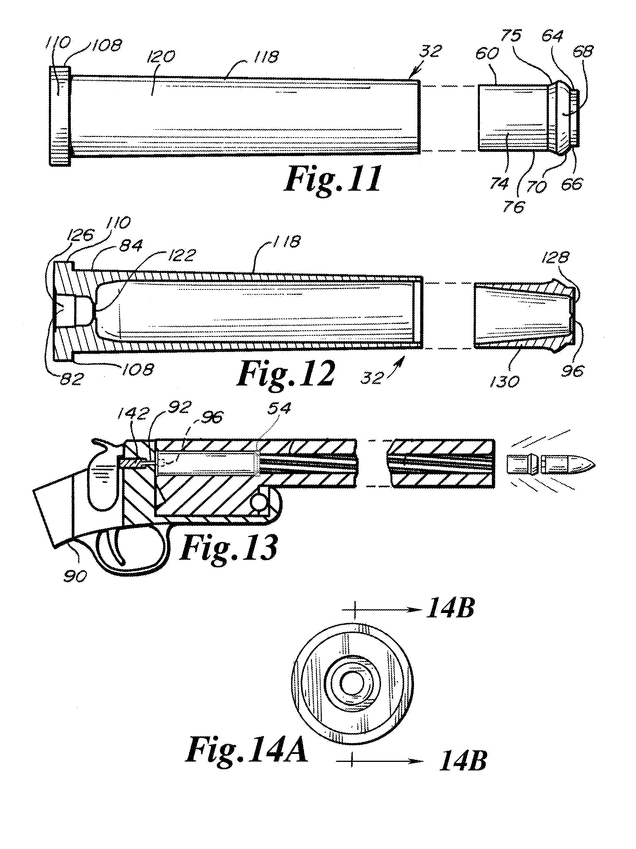
[0026] FIG. 11 is an exploded elevation view of the vessel of FIG. 9.
[0027] FIG. 12 is a cross sectional view of the vessel of FIG. 11.
[0028] FIG. 13 is a partial cross sectional view of a muzzleloading firearm firing a projectile with the cap portion of a propellant vessel being discharged from the barrel.
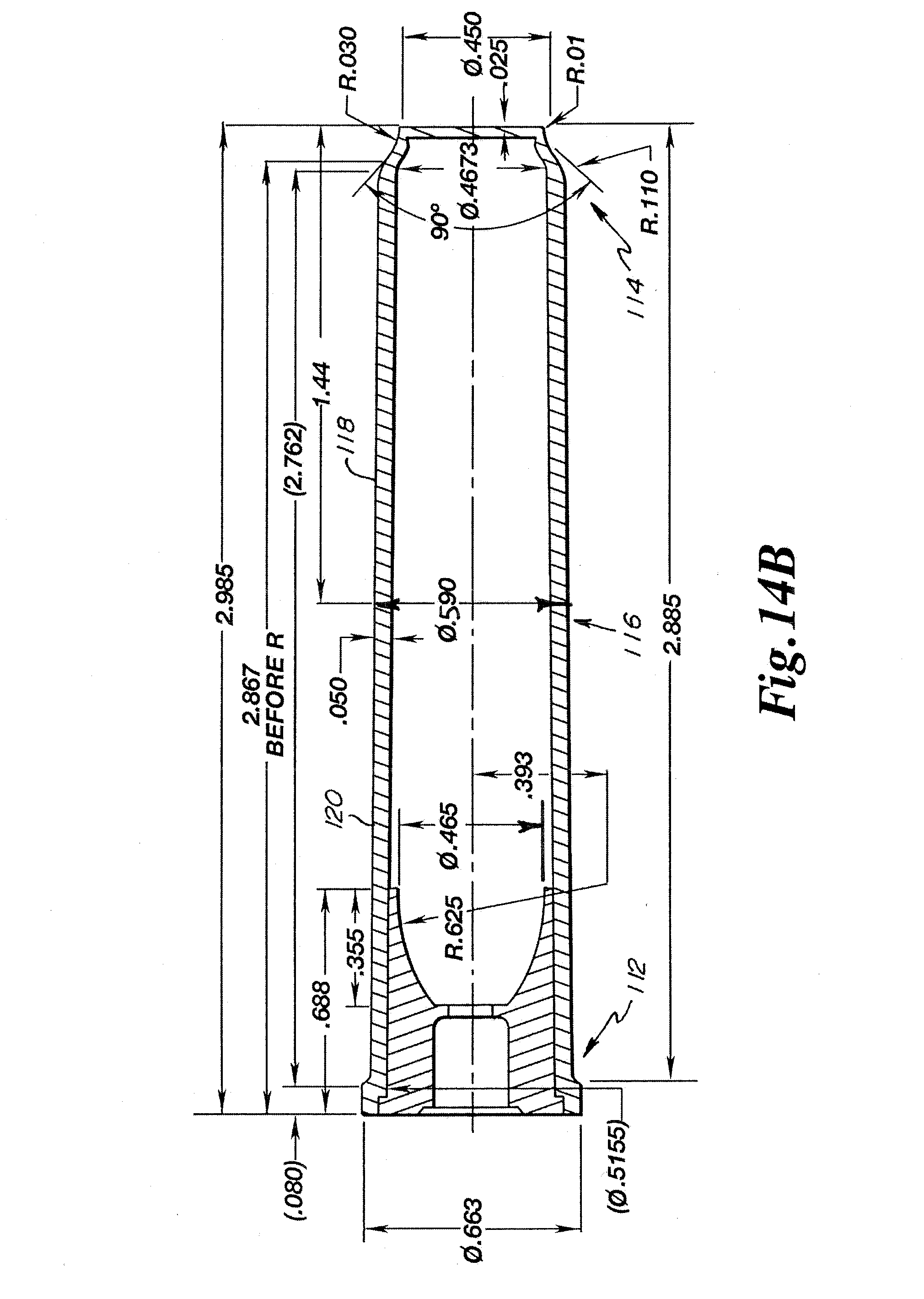
[0029] FIG. 14A is an end view showing a propellant containment vessel.
[0030] FIG. 14B is a cross-sectional view showing the propellant containment vessel shown in FIG. 14A.
[0031] FIG. 14C is an enlarged cross-sectional view showing a portion of the propellant containment vessel shown in FIG. 14B.
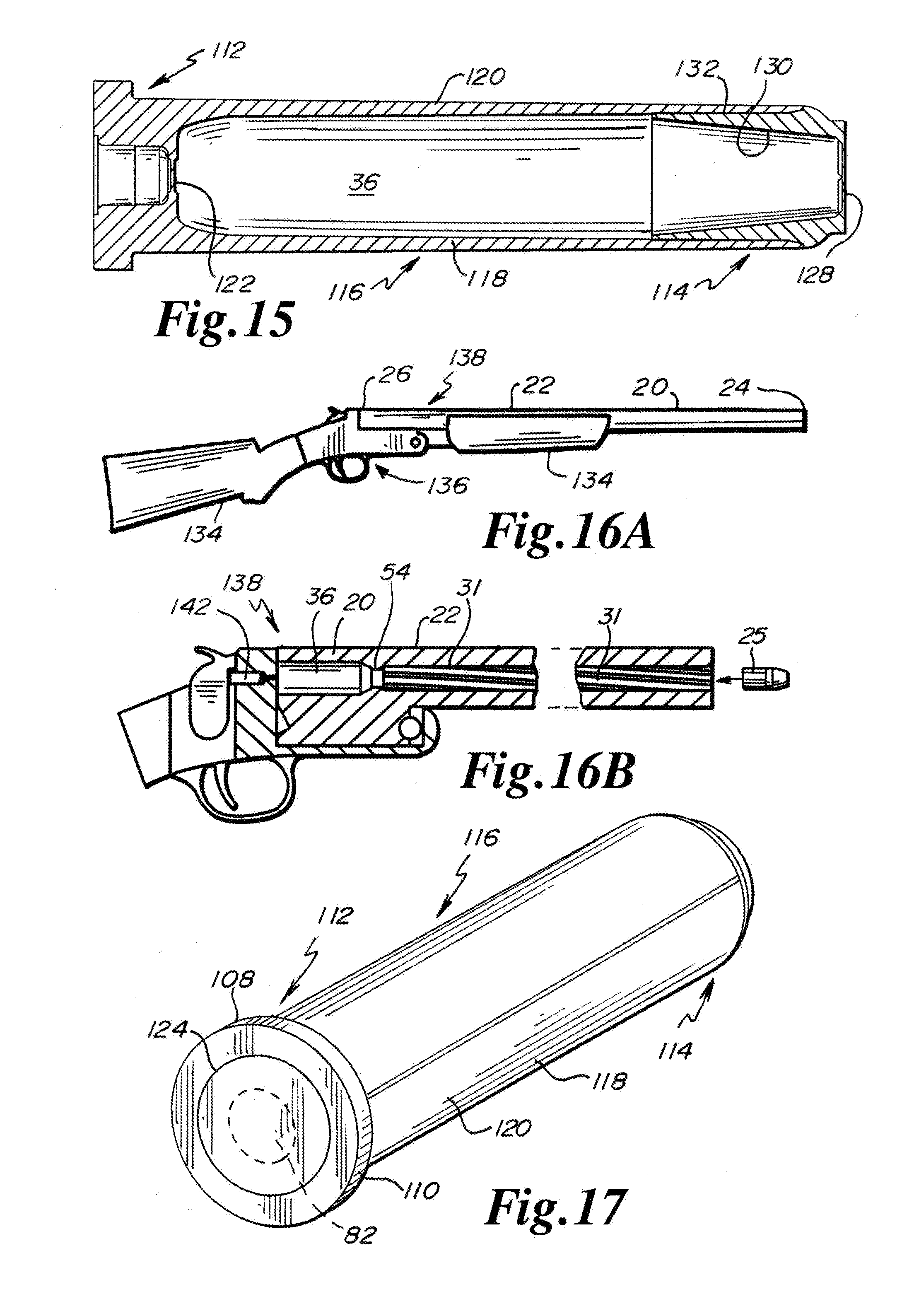
[0032] FIG. 15 is a cross-sectional view showing a propellant containment vessel.
[0033] FIG. 16A is a side view of a muzzle loader.
[0034] FIG. 16B is a cross-sectional side view of a muzzleloader.
[0035] FIG. 17 is a perspective view showing a propellant containment vessel.
[0036] While the invention is amenable to various modifications and alternative forms, specifics thereof have been depicted by way of example in the drawings and will be described in detail. It should be understood, however, that the intention is not to limit the invention to the particular embodiments described. On the contrary, the intention is to cover all modifications, equivalents, and alternatives falling within the spirit and scope of the invention as defined by the appended claims.
DETAILED DESCRIPTION OF THE INVENTION
[0037] Referring to FIGS. 1 and 4-12, in embodiments, a muzzleloader system comprises muzzle loader 20, a polymer propellant vessel 32 with propellant 106 hermetically sealed therein, a projectile 25 and a primer 38. In embodiments, the muzzle loader 20 comprises a stock 134, a receiver 136 and a barrel 22, the barrel 22 having a breech end 26, a muzzle end 24, and a barrel bore 31 with a barrel axis 82. In embodiments, the muzzle loader 20 is openable exposing a breech face 100 of the barrel 22 and a propellant containment vessel chamber 36 opening at the breech face 100. In embodiments, the propellant containment vessel chamber 36 extends at least 2.5 inches inwardly from the breech face 100. In embodiments, the propellant containment vessel chamber 36 has an annular flange recess 102 at the breech face 100 extending axially inwardly at least 0.08 inches. In embodiments, the barrel 22 has a constriction portion 54 at a forward end of the propellant containment vessel chamber 36 and a projectile receiving region 104 forward of the constriction portion.
[0038] Referring to FIGS. 4-12, in embodiments, the propellant containment vessel 32 is entirely formed of polymer and filled with the propellant 106. In embodiments, the propellant containment vessel 32 is elongate with a central axis and having a conforming shape to the propellant containment vessel chamber 36 and having a closed polymer head portion 112, a closed forward portion 114, and an intermediate portion 116 extending therebetween. In embodiments, the closed polymer head portion 112 has a centrally located primer receptacle 40, 82, without a primer therein, and a flange 108 extending therearound. In embodiments, the flange 108 has an exterior cylindrical flange surface 110 with an axial length of at least 0.08 inches. In embodiments, the intermediate portion 116 has a conical side wall 118 with a conical surface 120. In embodiments, the propellant containment vessel 32 has a closed polymer forward portion with an end wall and a conforming shape to the constriction portion. In embodiments, the propellant containment vessel 32 has a length to maximum diameter of the flange of at least 4:1. In embodiments, the projectile 25 is sized to be received in the barrel bore 31. In embodiments, the primer 38 is sized to be received in the receptacle. In embodiments, the receptacle is dimensioned and adapted to receive a selected primer 38. In embodiments, the receptacle is dimensioned and adapted to receive a centerfire primer used in shotgun shells.
[0039] Referring to FIGS. 4-12 and 17, in embodiments, the containment vessel 32 defines a cavity 140 having a volume between 0.40 and 0.50 cubic inches. In embodiments, the tapering conical sidewall 118 has a taper of at least 0.4 degrees. In embodiments, the propellant containment vessel comprises polyethylene. In embodiments, the closed polymer head portion 112 has a unitary webbing portion 122 at a bottom of a primer recess 126 in the primer receptacle 40,82. In embodiments, the closed polymer head portion 112 has is sealed by a manually removable closure 124 at the primer recess 126.
[0040] Referring to FIGS. 9-12 and 15-16B, in embodiments, the closed forward portion 114 has an end wall 128 and a unitary skirt 130 extending therefrom, the skirt 130 underlaying the tapering conical wall portion and joined thereto at an interface 132. In embodiments, the interface 132 is breachable upon ignition of the propellant 106 firing the projectile 25, whereby when the muzzleloader 20 is fired, the end wall 128 and unitary skirt 130 pass through the constriction portion 54 and are ejected from the muzzleloader 20 immediately behind the projectile 25. In embodiments, the end wall 128 and unitary skirt 130 deform as they pass through the constriction portion 54. In embodiments, the end wall 128 and unitary skirt 130 have a maximum diameter of less than the minimal inside diameter of the constriction portion 54.
[0041] Referring to FIGS. 1-3 and 13, an example method of using a muzzleloader 20 of a muzzleloader system may be described. In embodiments, the muzzleloader system comprises the muzzle loader 20, a polymer propellant vessel 32 with propellant 106 hermetically sealed therein, a projectile 25 and a primer 38. In embodiments, the muzzle loader 20 comprises a stock 134, a receiver 136 and a barrel 22. In embodiments, the barrel 22 has a breech end 26, a muzzle end 24, and a barrel bore 31 with a barrel axis 82. In embodiments, the muzzle loader 20 is openable to expose a breech face 100 of the barrel 22 and a propellant containment vessel chamber 36 opening at the breech face 100. In embodiments, the propellant containment vessel chamber 36 has an annular flange recess 102 at the breech face 100. In embodiments, the barrel 22 has a constriction portion 54 at a forward end of the propellant containment vessel chamber 36 and a projectile receiving region 104 forward of the constriction portion 54. In embodiments the propellant containment vessel 32 is formed of a thermoplastic polymer material (e.g., polyethylene). In embodiments, the propellant containment vessel 32 is elongate with a central axis and has a shape that conforms to the propellant containment vessel chamber 36. In embodiments, the propellant containment vessel 32 has a closed polymer head portion, a closed forward portion, and an intermediate portion extending therebetween. In embodiments, the closed polymer head portion has centrally located primer receptacle 40, 82, without a primer therein and a flange 108 extending therearound. In embodiments, the intermediate portion has a tubular side wall. In embodiments, the closed polymer forward portion has an end wall.
[0042] Still referring to FIGS. 1-3 and 13, In embodiments, the method comprises inserting the projectile 25 in the muzzle end 24 of the barrel 22 and seating the projectile 25 in the projectile seating region. In embodiments, the method comprises opening the breech portion 138 of the muzzle loader 20. In embodiments, the method comprises inserting the primer 38 in the primer receptacle 38 of the propellant containment vessel 32 after the propellant containment vessel 32 is in the propellant containment vessel chamber 36. In embodiments, the method comprises closing the breech portion 138 of the muzzle loader 20. In embodiments, the method comprises actuating a trigger mechanism whereby a firing pin 142 strikes a primer 38 and expanding gases from the primer 38 enter the propellant containment vessel chamber 36 igniting the propellant 106 therein.
[0043] In embodiments, the method comprises opening a seal at the primer receptacle 40, 82 when inserting the primer 38. In embodiments, the method comprises opening a seal at the primer receptacle 40, 82 before inserting the primer 38. In embodiments, the method comprises emptying the muzzle loader 20 without firing the muzzle loader 20, by opening the breech portion 138 of the muzzle loader 20, removing the unfired propellant containment vessel 32, pushing the projectile 25 from the projectile seating region and out of the muzzle end xx of the barrel 22, and closing the breech portion 138.
[0044] Referring to FIGS. 1 and 4-12, in embodiments, a muzzleloader propellant containment vessel 32 defines a cavity 140 for containing a propellant 106. In embodiments, muzzleloader propellant containment vessel 32 is configured for use with a primer 38, a projectile 25 and a muzzleloader 20. In embodiments, the muzzle loader 20 has a barrel 22 with a propellant containment vessel chamber 36 open rearwardly, a constriction portion 54 forward of the propellant containment vessel chamber 36 and a projectile receiving region 104 forward of the constriction portion 54. In embodiments, a projectile 25 is receivable in the barrel bore 31 at a muzzle end 24. In embodiments, a muzzleloader power cell system comprises the muzzleloader propellant containment vessel 32 hermetically sealed and filled with propellant 106. In embodiments, the propellant containment vessel 32 is elongate with a central axis and has a conforming shape to the propellant containment vessel chamber 36 of the muzzle loader 20. In embodiments, the propellant containment vessel 32 has a closed polymer head portion 112, a closed forward portion 114, and an intermediate portion 116 extending therebetween. In embodiments, the closed polymer head portion 112 has a central located primer receptacle 40, 82, without a primer therein, and a flange 108 extending therearound. In embodiments, the flange 108 has an exterior cylindrical flange surface 110 with an axial length of at least 0.08 inches. In embodiments, the intermediate portion 116 is tubular and has a conical side wall 118 with a conical surface 120. In embodiments, the closed polymer forward portion 114 has an end wall 128 and a conforming shape to the constriction portion 54. In embodiments, the propellant containment vessel 32 has a length to maximum diameter of the flange of at least 4:1.
[0045] Referring to FIGS. 1-5, a muzzle-loader bullet system may include a pre-packaged breech loaded propellant charge 106 and primer 38 for providing efficient loading and unloading of the muzzleloader 20. In embodiments, the muzzleloader 20 has barrel 20 defining a breech cavity 36 and a barrel bore 31. In embodiments, the barrel bore 31 extends between the breech cavity 36 and a muzzle end 24 of the barrel 20. In embodiments, a separator 54 is disposed between the breech cavity 36 and the barrel bore 31. The separator 54 may be configured as a constrictor portion having a reduced diameter portion less than the diameter of the bore preventing bullets sized to the barrel from being breech loaded. In embodiments, the propellant containment vessel 32 abuts against a rearward facing surface of the separator 54. In embodiments, the propellant containment vessel 32 has a forward end portion with a conforming surface that conforms to the rearward and upwardly facing constriction portion surface. In use, a projectile 25 is inserted in the muzzle end 24 of the barrel bore 31 and seats at a forward facing surface of the separator 54. The cup or vessel portion of the propellant containment vessel 32 may be injection molded, filled with propellant and then a cap 52 fastened or adhered or welded thereto. In embodiments, the cap 52 has a receptacle for a primer 38 to be inserted in the field. In embodiments, an ullage between the projectile 25 and the breech loaded propellant charge 106 may be eliminated or minimized with the configuration of the containment vessel 32 and/or separator 54. In embodiments, the containment vessel 32 has a closure on the cap 52 for keeping the vessel with propellant hermetically sealed prior to use. In use, the closure may be either removed, breeched by installation of the primer 38, or sacrificed during firing of the primer 38.
[0046] Referring to FIG. 1, a muzzleloader 20, for use with a propellant containment vessel 32 and a projectile 25, generally comprises a barrel 22 having a breech 23 (or breech cavity), a breech end 26, and a muzzle end 24. The barrel 22 can comprise a smooth bore (not shown) or a rifled bore 31 as depicted in FIG. 1. Referring to FIGS. 2 and 3, the muzzleloader 20 is conventionally loaded with a projectile 25 at the muzzle end by pushing the projectile down the bore towards the breech end 26 until the projectile is seated. The breech is accessed for loading of the propellant as shown in FIG. 1 and a propellant containment vessel 32 or cartridge is inserted into the breech. The primer 38 also is inserted into the primer receptacle 40. The breech is closed and is ready for firing.
[0047] Referring to FIGS. 4-8, in embodiments, the propellant containment vessel 32 is comprised of a cartridge cup portion or vessel portion 50 and a cap 52 with the primer receptacle 40. The cap has a closure for sealing the propellant in the vessel prior to us to maintain the integrity and to securely contain the propellant. A web that is unitary with the polymer cap may be a suitable enclosure. Such a web may be punctured by a suitably configured primer or it may be breeched by the firing of the primer. Alternatively a closure indicated by the dashed lines by be externally accessed by the use to remove same prior to insertion of the primer.
[0048] Referring to FIG. 5, suitable dimensions for the propellant containment vessel 32 are shown. These dimensions may vary .+-.5% in embodiments of the invention. These dimensions may vary .+-.10% in embodiments of the invention. These dimensions may vary .+-.2% in embodiments of the invention. The vessel portions, or cups, may be injection molded of polymers, such as polyethylene. Similarly the cap may be injection molded from polymers such as polyethylene. The cap is adhered to the vessel portion such as by adhesives, welding, mechanical connections. The vessel portion may be transparent and the caps may be color coded representative of types or quantities of propellant. The vessel portion and/or the cap may be transparent or translucent.
[0049] Referring to FIGS. 9-12, another embodiment is illustrated in which the cap 60 fits into the vessel portion 61 is at the forward end of the propellant containment vessel 62. The cap has a forward cylindrical portion 64 with a cylindrical surface 66, a tapered portion 68 with a tapered surface 70 rearward of the cylindrical surface, and another cylindrical portion 74 with a surface 76 rearward of the tapered surface 70 and separated therefrom by a step 76. The cap 60, after filling vessel portion, is inserted into and attached to the open mouth 78 of the vessel portion. The cap can be secured therein by a snap-fit, threads, adhesive, welding, or other means. The primer 38 may be secured into the primer recess 82 in the head portion 84 of the vessel portion 61.
[0050] Referring to FIG. 13, in embodiments, upon the firearm firing pin 92 striking the primer 96, the propellant ignites and the cap separates from the vessel portion, deforms as it moves past the constriction portion of the firearm, and is discharged out the barrel after the bullet. The cap may obturate and provide a rearward seal behind the bullet sealing in the expanding propellant gases. In other embodiments, a portion of the cap may separate, for example, the front face. In other embodiments, the cap may simply open and not have any portions separate.
[0051] The following United States patents are hereby incorporated by reference herein in their entirety except for patent claims and express definitions contained therein: U.S. Pat. Nos. 9,273,941; 9,261,335; 9,003,973; 8,875,633; 8,869,702; 8,763,535; 8,726,560; 8,590,199; 8,573,126; 8,561,543; 8,453,367; 8,443,730; 8,240,252; 8,146,505; 7,984,668; 7,621,208; 7,444,775; 7,441,504; 7,278,358; 7,225,741; 7,059,234; 6,931,978; 6,845,716; 6,752,084; 6,625,916; 6,564,719; 6,439,123; 6,178,889; 5,677,505; 5,492,063; 5,359,937; 5,216,199; 4,955,157; 4,169,329; 4,098,016; 4,069,608; 4,058,922; 4,057,003; 3,776,095; and 3,771,415. Components illustrated in the incorporated by reference references may be utilized with embodiments herein. Incorporation by reference is discussed, for example, in MPEP section 2163.07(B).
[0052] All of the features disclosed, claimed, and incorporated by reference herein, and all of the steps of any method or process so disclosed, may be combined in any combination, except combinations where at least some of such features and/or steps are mutually exclusive. Each feature disclosed in this specification may be replaced by alternative features serving the same, equivalent or similar purpose, unless expressly stated otherwise. Thus, unless expressly stated otherwise, each feature disclosed is an example only of a generic series of equivalent or similar features. Inventive aspects of this disclosure are not restricted to the details of the foregoing embodiments, but rather extend to any novel embodiment, or any novel combination of embodiments, of the features presented in this disclosure, and to any novel embodiment, or any novel combination of embodiments, of the steps of any method or process so disclosed.
[0053] Although specific examples have been illustrated and described herein, it will be appreciated by those of ordinary skill in the art that any arrangement calculated to achieve the same purpose could be substituted for the specific examples disclosed. This application is intended to cover adaptations or variations of the present subject matter. Therefore, it is intended that the invention be defined by the attached claims and their legal equivalents, as well as the illustrative aspects. The above described embodiments are merely descriptive of its principles and are not to be considered limiting. Further modifications of the invention herein disclosed will occur to those skilled in the respective arts and all such modifications are deemed to be within the scope of the inventive aspects.
* * * * *
D00000
D00001
D00002
D00003
D00004
D00005
D00006
D00007
XML
uspto.report is an independent third-party trademark research tool that is not affiliated, endorsed, or sponsored by the United States Patent and Trademark Office (USPTO) or any other governmental organization. The information provided by uspto.report is based on publicly available data at the time of writing and is intended for informational purposes only.
While we strive to provide accurate and up-to-date information, we do not guarantee the accuracy, completeness, reliability, or suitability of the information displayed on this site. The use of this site is at your own risk. Any reliance you place on such information is therefore strictly at your own risk.
All official trademark data, including owner information, should be verified by visiting the official USPTO website at www.uspto.gov. This site is not intended to replace professional legal advice and should not be used as a substitute for consulting with a legal professional who is knowledgeable about trademark law.