Ifs-r (integrated Flip-up Sight-rear) System, Ar-15/10 And M16/m4 Variants And Others
Wheeler; David Edmon
U.S. patent application number 16/247738 was filed with the patent office on 2019-07-25 for ifs-r (integrated flip-up sight-rear) system, ar-15/10 and m16/m4 variants and others. This patent application is currently assigned to WM C Anderson INC DBA Anderson Manufacturing. The applicant listed for this patent is WM C Anderson INC DBA Anderson Manufacturing. Invention is credited to David Edmon Wheeler.
| Application Number | 20190226802 16/247738 |
| Document ID | / |
| Family ID | 67299862 |
| Filed Date | 2019-07-25 |


View All Diagrams
| United States Patent Application | 20190226802 |
| Kind Code | A1 |
| Wheeler; David Edmon | July 25, 2019 |
IFS-R (INTEGRATED FLIP-UP SIGHT-REAR) SYSTEM, AR-15/10 AND M16/M4 VARIANTS AND OTHERS
Abstract
A firearm sight system is provided having a mounting rail with an upper surface. The mounting rail defines a pocket below the upper surface. A sight arm is pivotally connected to the rail and movable between an elevated position angularly offset from the upper surface of the rail and a stowed position in which the sight arm occupies the pocket and does not protrude above the upper surface of the rail.
| Inventors: | Wheeler; David Edmon; (Florence, KY) | ||||||||||
| Applicant: |
|
||||||||||
|---|---|---|---|---|---|---|---|---|---|---|---|
| Assignee: | WM C Anderson INC DBA Anderson
Manufacturing Hebron KY |
||||||||||
| Family ID: | 67299862 | ||||||||||
| Appl. No.: | 16/247738 | ||||||||||
| Filed: | January 15, 2019 |
Related U.S. Patent Documents
| Application Number | Filing Date | Patent Number | ||
|---|---|---|---|---|
| 62619855 | Jan 21, 2018 | |||
| Current U.S. Class: | 1/1 |
| Current CPC Class: | F41G 1/08 20130101; F41G 1/16 20130101 |
| International Class: | F41G 1/16 20060101 F41G001/16 |
Claims
1. A firearm sight system comprising: a mounting rail having an upper surface; the mounting rail defining a pocket below the upper surface; a sight arm pivotally connected to the rail and movable between an elevated position angularly offset from the upper surface of the rail and a stowed position in which the sight arm occupies the pocket and does not protrude above the upper surface of the rail.
Description
CROSS-REFERENCE TO RELATED APPLICATIONS
[0001] This application claims the benefit of U.S. Provisional Patent Application No. 62/619,855 filed on Jan. 21, 2018, entitled "IFS-R (Integrated Flip-Up Sight-Rear) System, AR-15/10 and M16/M4 Variant and Others", which is hereby incorporated by reference in its entirety for all that is taught and disclosed therein.
FIELD OF THE INVENTION
[0002] The present invention relates to an integrated flip-up sight-rear system, and more particularly, to AR-15/10 and M16/M4 variants and others.
BACKGROUND OF THE INVENTION
[0003] The modern AR-15 style rifle platform is primarily comprised of MIL-SPEC (Military Specification) components originally derived from the M16A1/A2, M4A1 and M16A4 variants. Platforms include semi-automatic, burst and full-automatic fire control versions, as well as a multitude of caliber configurations. Most modern AR-15 components have retained either MIL-SPEC adherence and/or a close resemblance to the original 1956 Eugene Stoner and L. James Sullivan Armalite AR-15 design. All M16A1/A2, M4A1 and M16A4 variants retain absolute adherence to MIL-SPEC requirements, as these platforms are intended for applications in standardized military service.
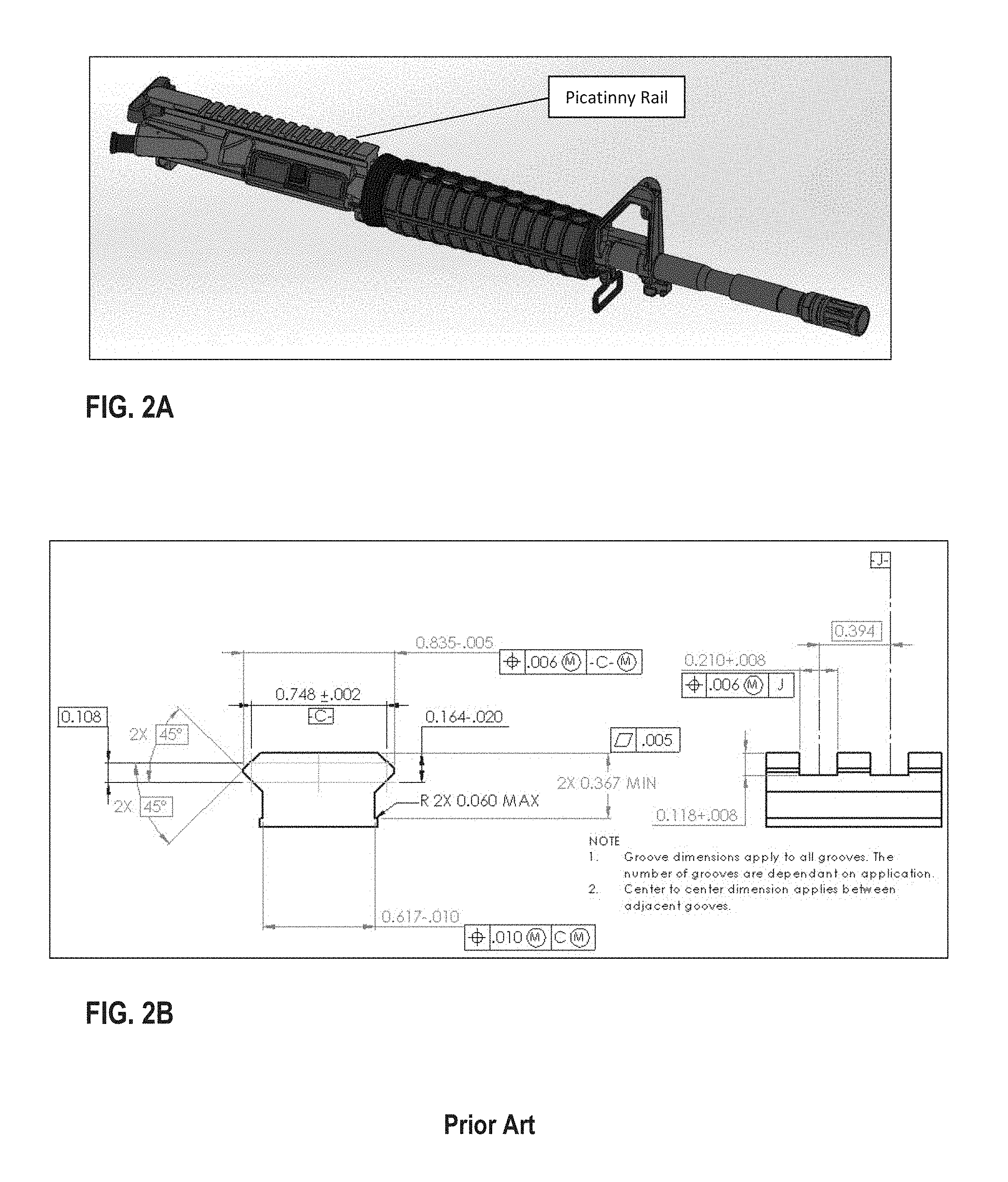
[0004] The MIL-SPEC design utilizes an integrated Rear Sight, commonly referred to as an "Iron Sight" (see FIG. 1). Although the M4 variant is an exception, as it provides a Picatinny rail (MIL-STD-1913) for the mounting of its sight/optical aid (see FIG. 2). This type of configuration is commonly referred to as "Optic Ready", inferring that a sight or optical device must first be installed on the firearm for accurate target acquisition. With the advent of the M4 configuration and further popularization of Upper Receiver designs without an integrated rear sight, a typical approach to provide sighting capabilities followed suit with the M4 application by utilizing Picatinny rail-mounted devices (see FIG. 3). Consequently, there are now a multitude of sight/optical aid devices available; several of which mimic the original carrying handle with integrated sight style (see FIG. 4).
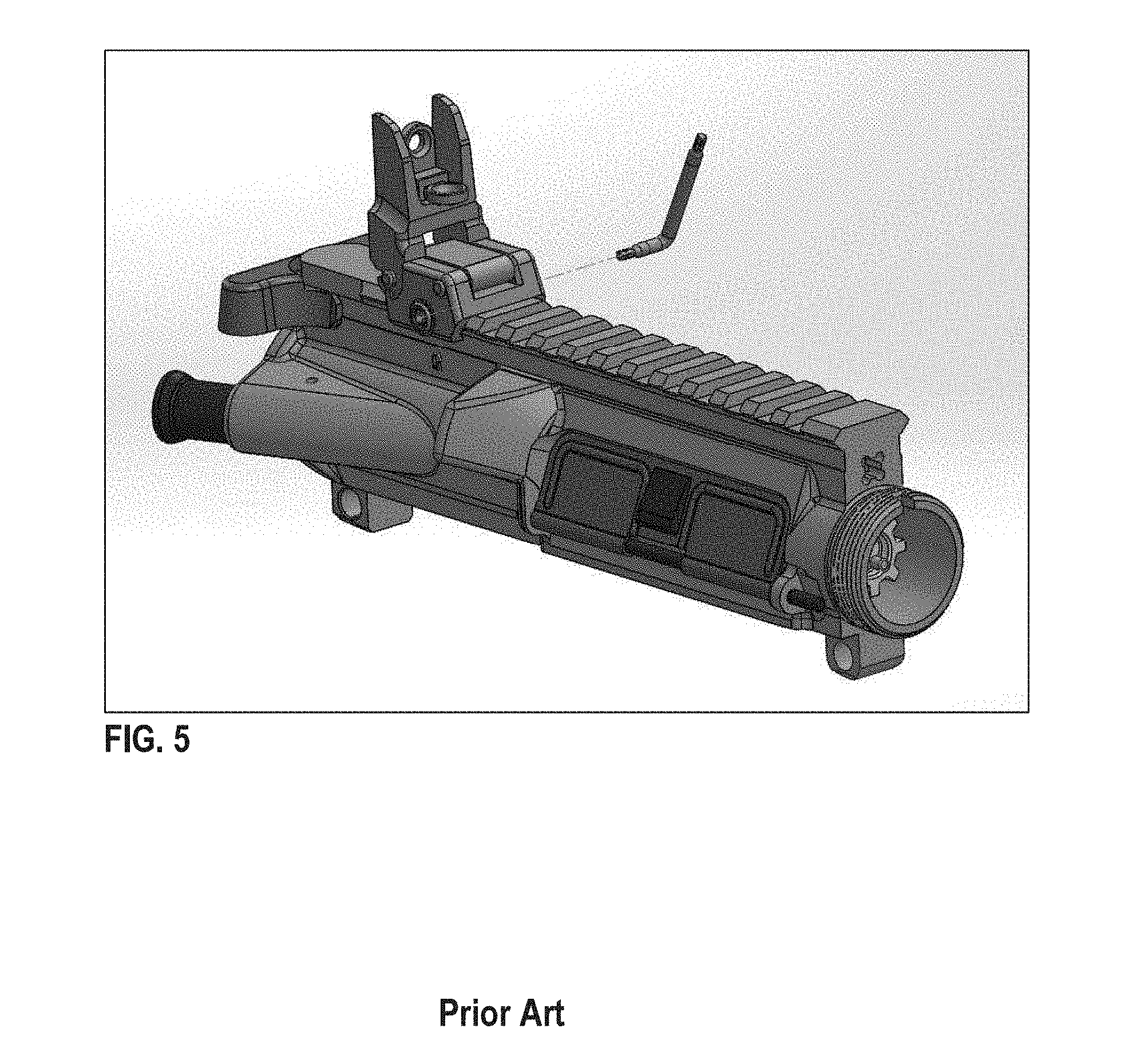
[0005] The most common and relatively economical solution to an Optic Ready firearm is the flip-up style sight (see FIG. 5). However, this design is rather impractical, as it often requires the use of a special tool, such as a hex driver, screw driver, Torx.RTM. driver, etc., to mount, adjust or uninstall on the Picatinny rail. Furthermore, many of these devices are captivated to the Picatinny rail by a single fastener, screw or bolt, and are consequently susceptible to loosening during use and the subsequent loss of sight calibration or zero; thus, creating the added burden of always having to carry a special tool for this purpose, which could prove to be especially burdensome in a tactical environment.
[0006] Moreover, the deviation of reliance upon Iron Sights to an electronic optical device, which can illuminate reticles, provide electronic magnification and/or thermal imaging, tends to produce an undesired dependence, thus effecting a considerable tactical disadvantage as these optics require a constant, replenishing source of power (i.e. batteries, power cells, etc.). However, once a source of power is no longer readily available, the device would be rendered inoperable, causing conditions to rapidly deteriorate.
[0007] Additionally, while many configurations of the flip-up type utilize a locking mechanism, which must be pressed or released to permit folding, they are typically not impact resistant once positioned into the flip-up orientation, making them susceptible to strike or impact damage.
[0008] Another problematic condition of flip-up style sights is a deviation from the original MIL-SPEC sight centerline to the bore centerline. As most rear flip-up style sights do not provide elevation adjustment or compensation, this condition can exceed the vertical adjustment travel (+/-) of the front sight post. As such, optics that are installed between flip-up sights can further compound this condition when original MIL-SPEC centerlines are not maintained (see FIG. 6).
[0009] The limitations of the prior art are addressed by providing a firearm sight system having a mounting rail with an upper surface. The mounting rail defines a pocket below the upper surface. A sight arm is pivotally connected to the rail and movable between an elevated position angularly offset from the upper surface of the rail and a stowed position in which the sight arm occupies the pocket and does not protrude above the upper surface of the rail.
BRIEF DESCRIPTION OF THE DRAWINGS
[0010] FIG. 1 shows a MIL-SPEC Integrated Rear Sight with Lower Receiver and Barrel Assembly removed for clarity.
[0011] FIGS. 2A and 2B show an Upper Receiver with MIL-STD-1913 Picatinny Rail.
[0012] FIG. 3A to 3D show examples of Picatinny Rail-Mounted Sight/Optical Aid Devices.
[0013] FIG. 4 shows a Picatinny Rail-Mounted Carrying Handle with Iron Sight.
[0014] FIG. 5 shows a Flip-Up Style Sight Mounted on Upper Receiver Picatinny Rail.
[0015] FIG. 6 illustrates Centerline Deviations.
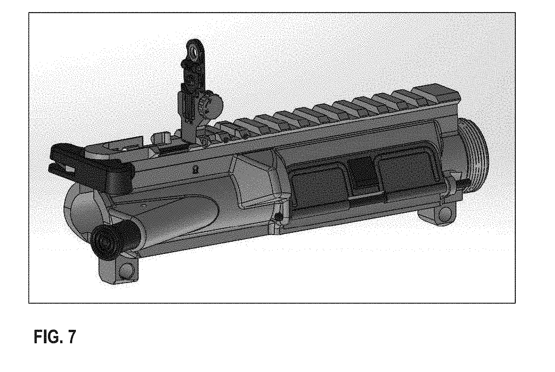
[0016] FIG. 7 is a side view of an IFS-R Upper Receiver Assembly.
[0017] FIG. 8 is a side view of the IFS-R Folded into Upper Receiver.
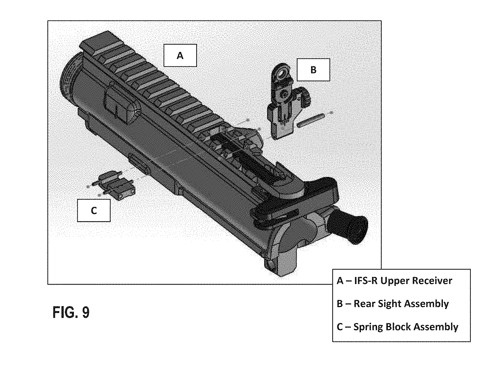
[0018] FIG. 9 illustrates IFS-R Major Components.
[0019] FIG. 10 illustrates a Rear Sight Assembly.
[0020] FIG. 11 illustrates a Spring Block Assembly.
[0021] FIG. 12 shows a Traverse Screw Adjustment.
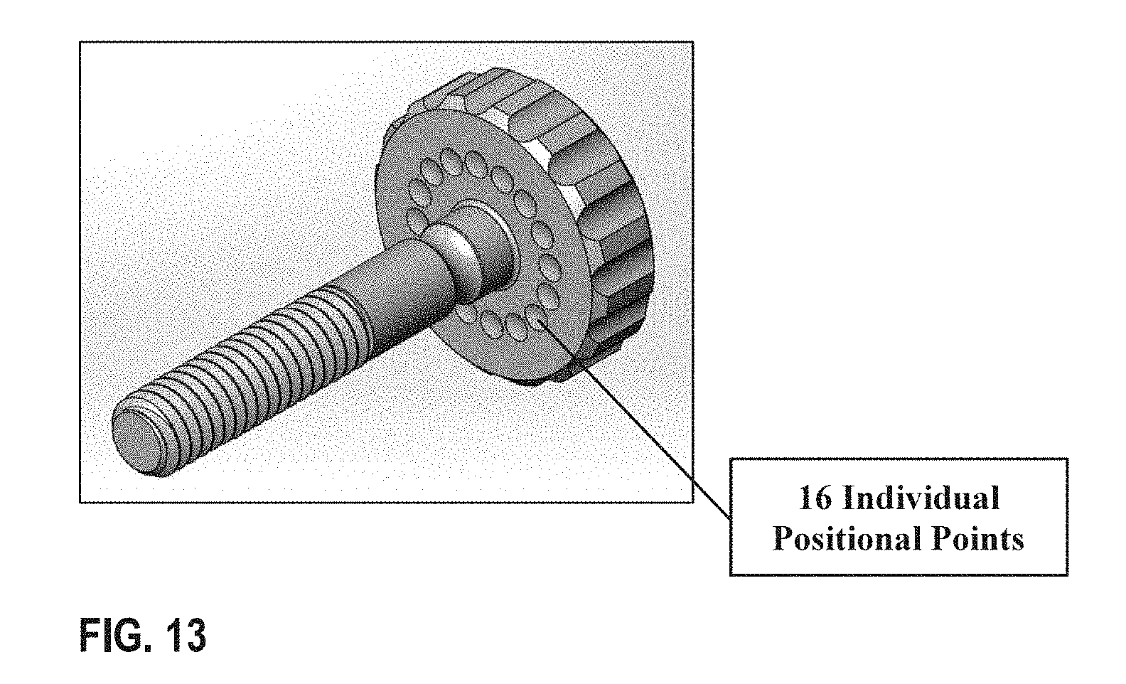
[0022] FIG. 13 is an exploded view of Positional Points on Traverse Screw.
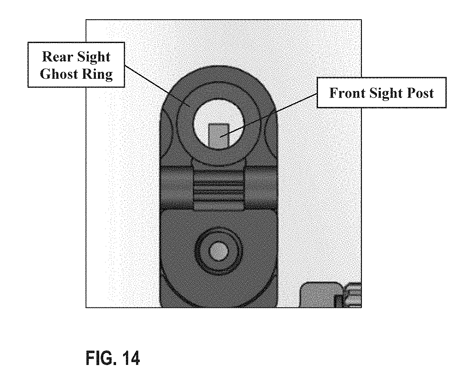
[0023] FIG. 14 is an exploded view of a rear sight Ghost Ring and Front Sight Post.
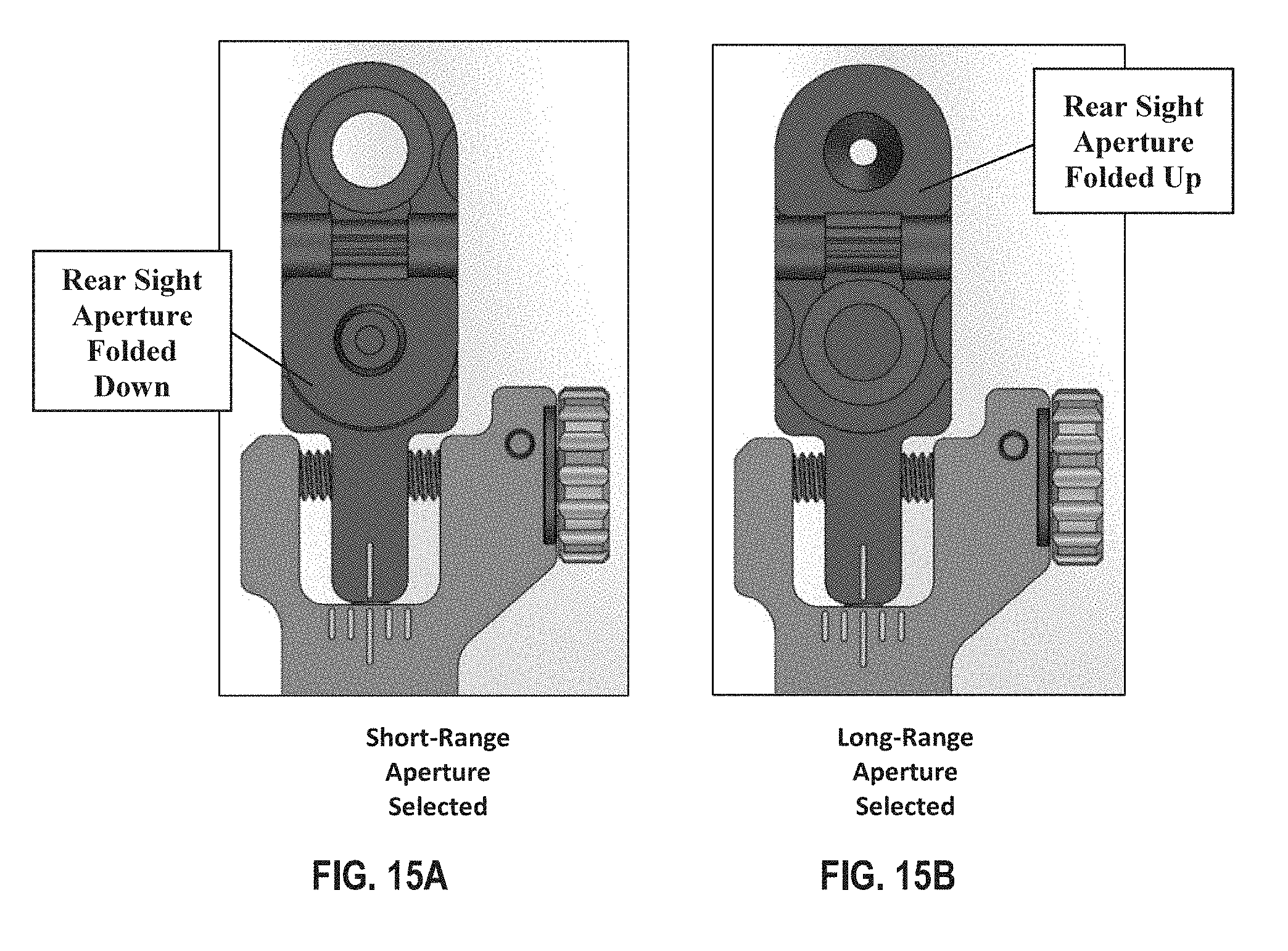
[0024] FIGS. 15A and 15B illustrate Aperture Sizes.
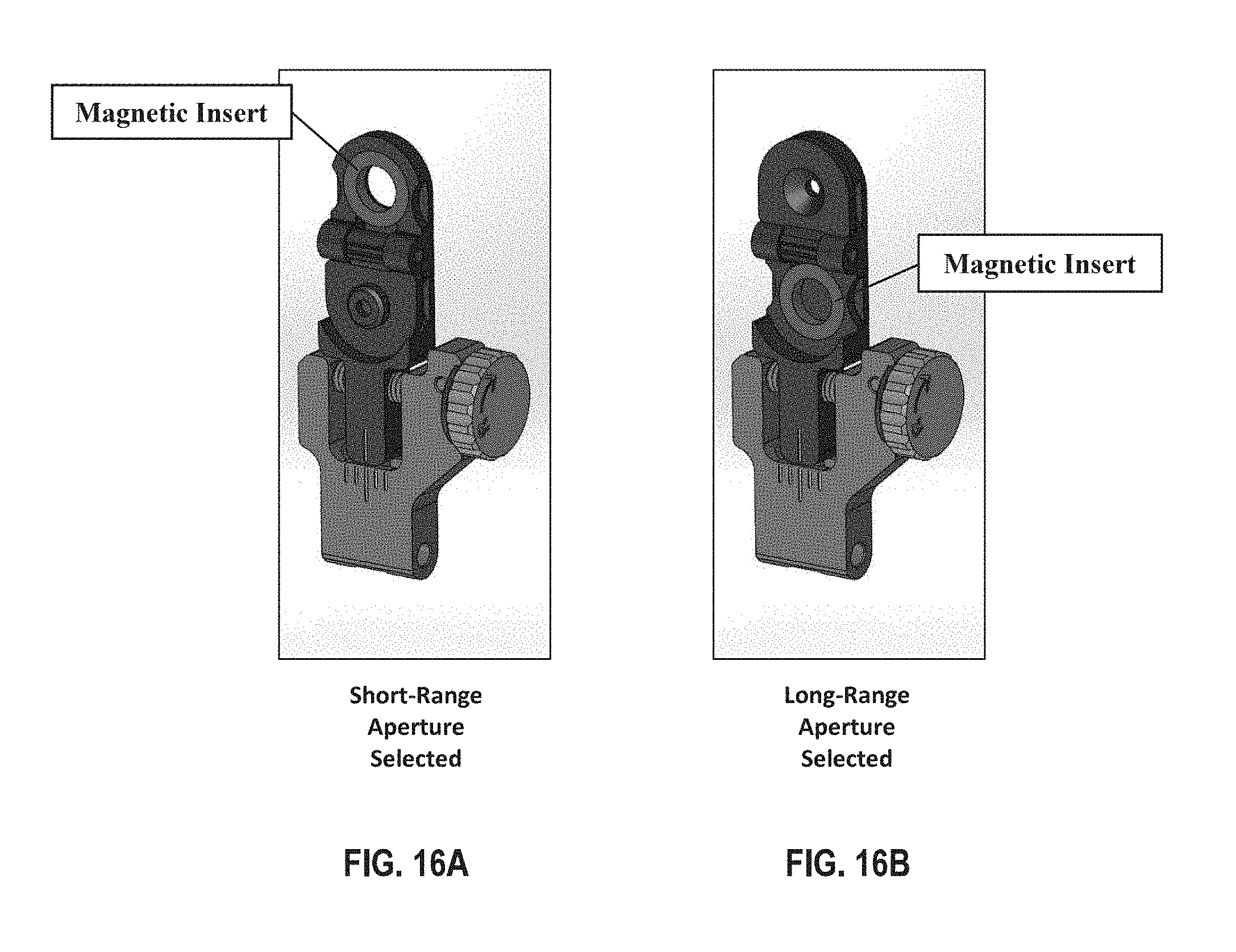
[0025] FIGS. 16A and 16B illustrate Magnetic Inserts.
[0026] FIG. 17 is a Plain View-Top-Sight Down.
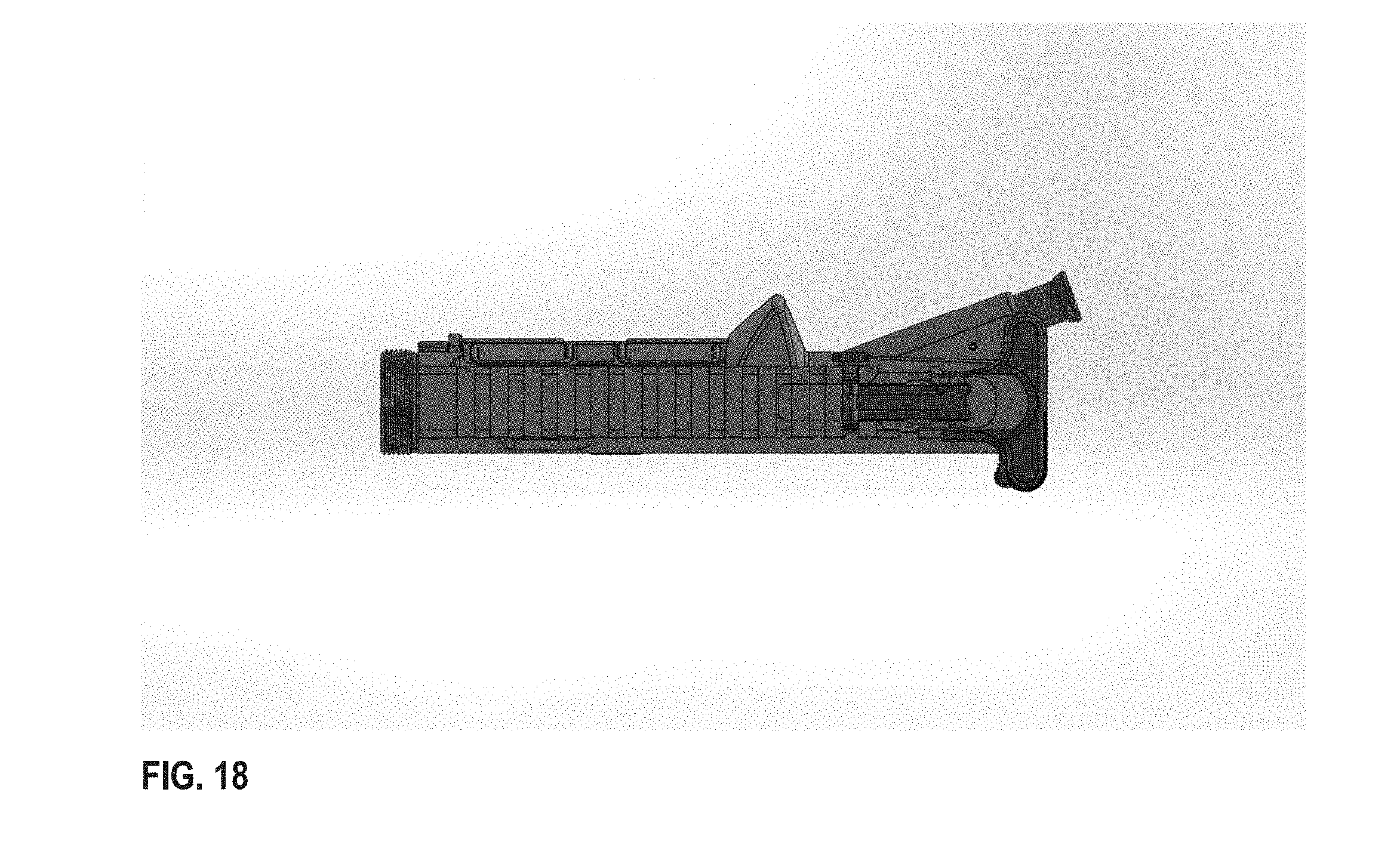
[0027] FIG. 18 is a Plain View-Top-Sight Up.
[0028] FIG. 19 is a Side Sectional View, Mid-Plane-Sight Down.
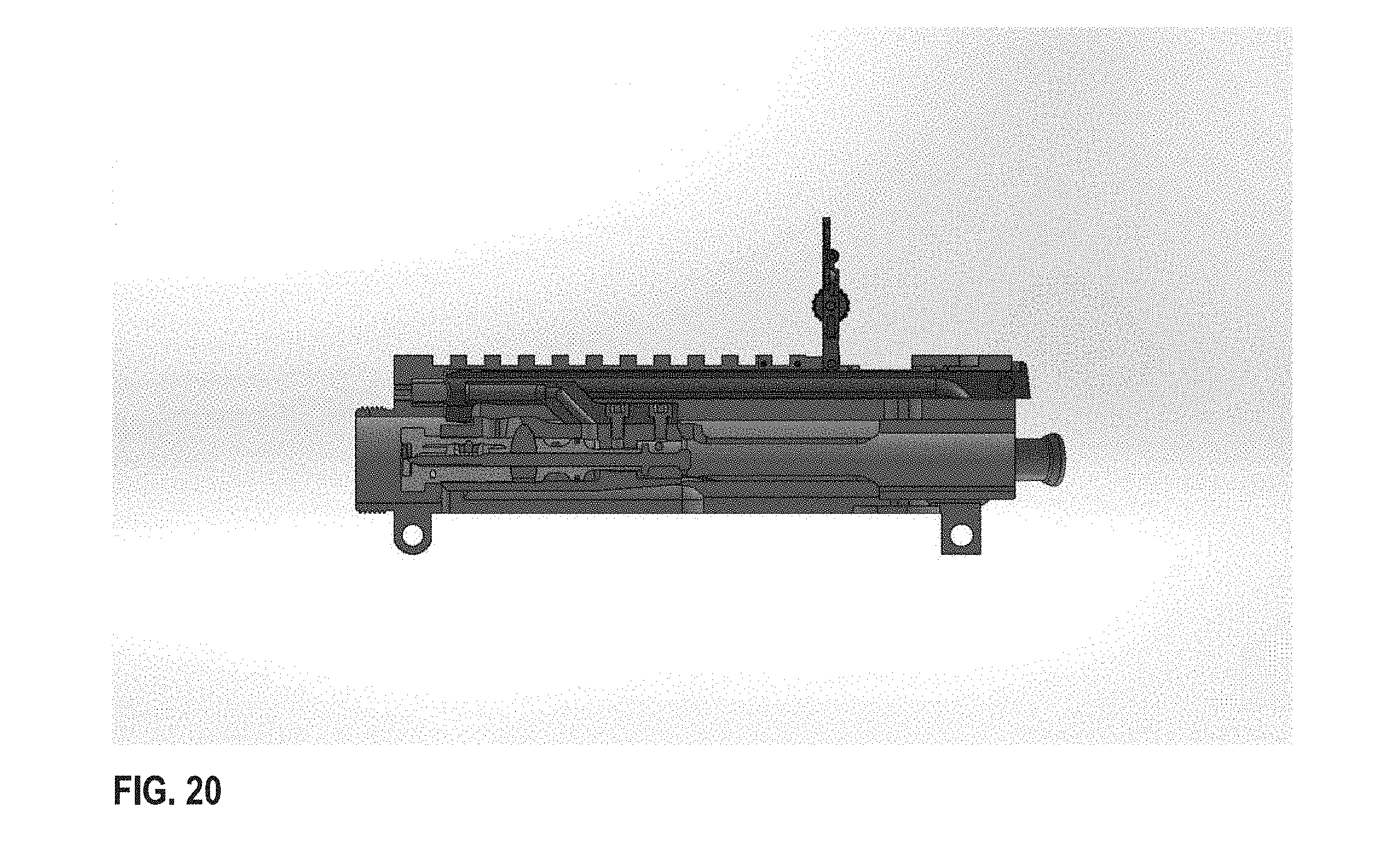
[0029] FIG. 20 is a Side Sectional View, Mid-Plane-Sight Up.
DESCRIPTION OF THE CURRENT EMBODIMENT
[0030] The IFS-R (INTEGRATED FLIP-UP SIGHT-REAR) SYSTEM provides increased functionality to the Optic Ready-style Upper Receiver with a built-in, adjustable, flip-up rear sight (see FIG. 7). The top rear section of the Upper Receiver is machined with a profiled pocket in which the rear sight is designed to fold down within the Picatinny rail when not in use (see FIG. 8).
[0031] The IFS-R is comprised of the following major components (see FIG. 9): [0032] IFS-R Upper Receiver [0033] Rear Sight Assembly (see FIG. 10) [0034] Spring Block Assembly
[0035] The folding and unfolding of the IFS-R is guided and supported by two spring-loaded ball bearing detents within the Spring Block Assembly (see FIG. 11). These detents orientate/lock the sight in the upright position and hold the device down in the folded position. Sight travel is limited to 90 degrees on the Pivot Pin axis by inherent design. The spring-loaded captivation of the IFS-R also serves to mitigate impact or strike upon the device by simply folding to prevent sight damage.
[0036] Traverse adjustment of the IFS-R is performed by clockwise or counterclockwise rotation of the Traverse Screw, resulting in left or right movement of the Rear Sight Post (see FIG. 12). Screw rotational setting is maintained by 16 individual positional points around the screw axis (see FIG. 13). A spring-loaded Ball Bearing assembled within the Rear Sight Post Base engages the appropriate positional point on the Traverse Screw as it is rotated during sight adjustment. This function also serves to provide constant spring pressure upon the Traverse Screw to ensure sight setting integrity upon strike or impact. Under spring protection, the body of the Traverse Screw can be used to elevate the IFS-R into the upright position. Folding of the IFS-R is simply performed by rotating the device rearward upon the Pivot Pin axis.
[0037] A Rear Sight Aperture is assembled into the Rear Sight Post, providing a typical ghost ring, center-hold sight picture (see FIG. 14). Two aperture sizes are provided in accordance with MIL-SPEC standards (see FIG. 15): [0038] Long-range, >300 meters (small hole) [0039] Short-range, <300 meters (large hole)
[0040] Aperture selection is made by rotating the Rear Sight Aperture about the pivot axis. Milled steps are provided on each side of the Rear Sight Post to aid in lifting the aperture from either available position. The short-range ghost ring is by default integrated into the Rear Sight Post. As the Rear Sight Aperture is orientated within the Rear Sight Post it is automatically captivated by magnetic force. Two Magnetic Inserts are assembled into the Rear Sight Post to generate said force (see FIG. 16). To select the long-range aperture, simply rotate the Rear Sight Aperture into the upright position. To select the short-range aperture, likewise, rotate the Rear Sight Aperture into the downward position.
[0041] This application is applicable to additional firearm platforms and should not be construed as limited to AR15/10 and/or M16/M4 platforms alone.
* * * * *
D00000
D00001
D00002
D00003
D00004
D00005
D00006
D00007
D00008
D00009
D00010
D00011
D00012

D00013
D00014
D00015
D00016
D00017

D00018
D00019

D00020
XML
uspto.report is an independent third-party trademark research tool that is not affiliated, endorsed, or sponsored by the United States Patent and Trademark Office (USPTO) or any other governmental organization. The information provided by uspto.report is based on publicly available data at the time of writing and is intended for informational purposes only.
While we strive to provide accurate and up-to-date information, we do not guarantee the accuracy, completeness, reliability, or suitability of the information displayed on this site. The use of this site is at your own risk. Any reliance you place on such information is therefore strictly at your own risk.
All official trademark data, including owner information, should be verified by visiting the official USPTO website at www.uspto.gov. This site is not intended to replace professional legal advice and should not be used as a substitute for consulting with a legal professional who is knowledgeable about trademark law.