Ventilation Device
Ho; Tsung-Te
U.S. patent application number 15/878430 was filed with the patent office on 2019-07-25 for ventilation device. The applicant listed for this patent is Tsung-Te Ho. Invention is credited to Tsung-Te Ho.
| Application Number | 20190226701 15/878430 |
| Document ID | / |
| Family ID | 67299206 |
| Filed Date | 2019-07-25 |


| United States Patent Application | 20190226701 |
| Kind Code | A1 |
| Ho; Tsung-Te | July 25, 2019 |
VENTILATION DEVICE
Abstract
A more simple and convenient assembly and disassembly ventilation device is disclosed, comprising a housing having an receiving space therein, both sides of which are provided with an air inlet and an air outlet communicating with the receiving space; a plurality of positioning member disposed on the inner wall of the top of the housing; a fan module detachably disposed in the receiving space of the housing and fastened to the positioning member; and a power control device disposed in the receiving space with its shell connected to the inner wall corresponding to the housing in a detachable manner. The power control device is electrically connected with the fan module, and has a wire-arranging element for fixing the electric wires of the fan module.
| Inventors: | Ho; Tsung-Te; (Taoyuan City, TW) | ||||||||||
| Applicant: |
|
||||||||||
|---|---|---|---|---|---|---|---|---|---|---|---|
| Family ID: | 67299206 | ||||||||||
| Appl. No.: | 15/878430 | ||||||||||
| Filed: | January 24, 2018 |
| Current U.S. Class: | 1/1 |
| Current CPC Class: | F24F 2007/002 20130101; F24F 7/10 20130101; F24F 13/20 20130101; F24F 7/08 20130101 |
| International Class: | F24F 7/08 20060101 F24F007/08; F24F 7/10 20060101 F24F007/10 |
Claims
1. A ventilation device comprising: a housing (1) having an receiving space (11) disposed therein, an air inlet (12) and an air outlet (13) disposed at both sides of the receiving space (11) and communicating with the receiving space (11), a baffle piece (131) pivotally disposed at the air outlet (13), and a bottom cover (14) disposed at a bottom of the housing; a plurality of positioning members (2) disposed on an inner wall of a top of the housing (1); a fan module (3) detachably disposed in the receiving space (11) of the housing (1) and fastened to the positioning members (2); and a power control device (4) disposed in the receiving space (11) and detachably connected to the inner wall of the housing (1); wherein the power control device (4) is electrically connected with the fan module (3) and has a wire-arranging element (41) for fixing the electric wires of the fan module (3).
2. The ventilation device according to claim 1, wherein the fan module (3) includes a motor (31) fastened to positioning member (2), a plurality of fixing pieces (311) disposed around an outer edge of the motor (31), a plurality of snap slots (312) disposed on one end of the fixing pieces (311) and fastened to the positioning member (2).
3. The ventilation device according to claim 2, wherein one of the fixing pieces (311) is inwardly recessed with a receiving groove (313) for receiving an electric wire of the fan nodule (3).
4. The ventilation device according to claim 2, wherein the wire-arranging element (41) is disposed at one side edge of the power control device (4), and is a non-closed loop hook for fixing the electric wire of the fan module (3) therein.
5. The ventilation device according to claim 2, wherein the power control device (4) is connected to the inner wall of the housing (1) by magnetic attraction.
6. The ventilation device according to claim 1, wherein the power control device (4) is connected to the inner wall of the housing (1) by a hooking manner.
7. The ventilation device according lo claim 1, wherein the power control device (4) is connected to the inner wall of the housing (1) by an adhering manner.
Description
BACKGROUND OF INVENTION
1. Field of the Invention
[0001] The present invention relates generally to a technical field of ventilation device, and more particularly to a ventilation device which is mounted on a ceiling or a wall of a bathroom and capable of ventilating the bathroom.
2. Description of Related Art
[0002] The ventilation device has been widely used in the bathroom of the family because of its function of adjusting the air and changing the air flow. Conventional ventilation devices comprise a housing defining an internal passageway, a fan rotationally disposed within the internal passageway, and a motor disposed in the internal passageway to drive the fan to rotate. The housing has an air inlet and an air outlet communicating with the internal passageway and the outside. When air enters the internal passageway from the air inlet, the fan located in the internal passageway guides the air out of the environment from the air outlet.
[0003] However, after the conventional ventilation device is used for a period of time, the exhaust efficiency of the fan located in the housing may be reduced due to dust accumulation. This may even cause damage to the motor that drives the fan to rotate. When replacing the motor, it is necessary to hold the housing with one hand and remove the screws that lock the housing and the fan and then the motor can be taken out from the internal passageway. In this way, not only is the process of taking out the motor quite inconvenient, but also, after replacing the motor, the screws need to be aligned with the screw holes for re-locking, making the replacement process more difficult. Therefore, the structural design of the conventional ventilation device still needs to be improved.
[0004] In view of this, how to improve the above problems and develop a more simple and convenient way of disassembling and assembling the ventilation device has become the subject of the present invention.
SUMMARY OF THE INVENTION
[0005] It is an object of the present invention to provide a ventilation device that is simpler and more convenient to disassemble and assemble.
[0006] In order to solve the above problems and achieve the purpose of the present invention, the technical means of the present invention are that a ventilation device comprises a housing (1) having an receiving space (11) disposed therein, an air inlet (12) and an air outlet (13) disposed at both sides of the receiving space (11) and communicating with the receiving space (11), and a bottom cover (14) disposed at a bottom of the housing;
[0007] a plurality of positioning members (2) disposed on an inner wall of a top of the housing (1);
[0008] a fan module (3) detachably disposed in the receiving space (11) of the housing (1) and fastened to the positioning members (2); and
[0009] a power control device (4) disposed in the receiving space (11) and detachably connected to the inner wall of the housing (1); wherein the power control device (4) is electrically connected with the fan module (3) and has a wire-arranging element (41) for fixing the electric wires of the fan module (3).
[0010] More preferably, wherein the fan module (3) includes a motor (31) fastened to positioning member (2), a plurality of fixing pieces (311) disposed around an outer edge of the motor (31), a plurality of snap slots (312) disposed on one end of the filing pieces (311) and fastened to the positioning member (2).
[0011] More preferably, wherein one of the fixing pieces (311) is inwardly recessed with a receiving groove (313) for receiving an electric wire of the fan module (3).
[0012] More preferably, wherein the wire-arranging element (41) is disposed at one side edge of the power control device (4), and is a non-closed loop hook for fixing the electric wire of the fan module (3) therein.
[0013] More preferably, wherein the power control device (4) is connected to the inner wall of the housing (1) by magnetic attraction.
[0014] More preferably, wherein the power control device (4) is connected to the inner wall of the housing (1) by a hooking manner.
[0015] More preferably, wherein the power control device (4) is connected to the inner wall of the housing (1) by an adhering manner.
[0016] The present invention may achieve the following functions:
[0017] Firstly, with the design of fastening the fan module (3) to the positioning member (2) in a detachable manner, a user can push the fan module (3) to slide the fan module (3) from the side edge of the positioning member (2) and remove out of the housing (1) to allow repair and maintenance more simple and convenient.
[0018] Secondly, through the collaboration of wire-arranging element (41) and receiving groove (313), the electric wires between the fan module (3) and the power control device (4) can be fixed to achieve good wire-arranging effect and solve the problem of electric wire storage.
[0019] Thirdly, with the design of connecting the power control device (3) with the inner wall corresponding to the housing (1) in a detachable manner, the assembly and disassembly of the power control device (3) is more simple and convenient, and the installed power control device (3) is firmly fixed.
BRIEF DESCRIPTION OF THE DRAWINGS
[0020] FIG. 1 is a schematic stereographic diagram of the present invention;
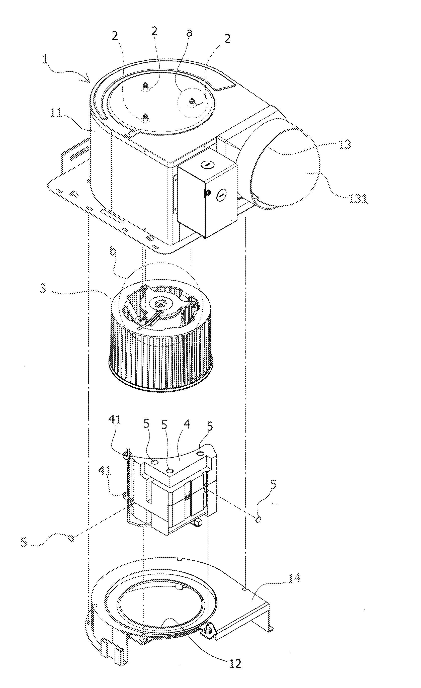
[0021] FIG. 2 is a schematic exploded diagram of the present invention.
[0022] FIG. 2a is an enlarged schematic diagram of FIG. 2, part a;
[0023] FIG. 2b is an enlarged schematic diagram of FIG. 2, part b;
[0024] FIGS. 3 and 4 are schematic implementation diagrams of the fan module of the present invention.
DETAILED DESCRIPTION OF THE INVENTION
[0025] Referring to FIG. 1 and FIG. 2, the figures show a ventilation device used in a bathroom. The ventilation device comprises a housing (1) having an receiving space (11) disposed therein, an air inlet (12) and an air outlet (13) disposed at both sides of the receiving space (11) and communicating with the receiving space (11), a baffle piece (131) pivotally disposed at the air outlet (13), and a bottom cover (14) disposed at a bottom of the housing; a fan module (3) detachably disposed in the receiving space (11) of the housing (1) and fastened to the positioning member (2); and a power control device (4) disposed in the receiving space (11) with its shell connected to the inner wall corresponding to the housing (1) in a detachable manner. The power control device (4) is electrically connected with the fan module (3), and has a wire-arranging element (41) for fixing the electric wires of the fan module (3).
[0026] With the design of fastening the fan module (3) to the positioning member (2) in a detachable manner, a user can push the fan module (3) to slide the fan module (3) from the side edge of the positioning member (2) and remove out of the housing (1) to allow repair and maintenance more simple and convenient.
[0027] The above two figures also show that the power control device (4) can be connected to the inner wall corresponding to the housing (1) by using magnet (5) in a magnetic attraction manner. Of course, in addition to using magnet (5) in a magnetic attraction manner, hooking (not shown in the figure) or adhering (not shown in the figure) may also be used for connecting to the inner wall corresponding to the housing (1). As a result, the installed power control device (4) can be more firmly fixed and will not be fell off in removing the bottom cover (14) of the housing (1) during maintenance. In addition, through the methods of magnetic attraction, hooking (not shown in the figure) or adhering (not shown in the figure), there is no need to use screws for connection between the power control device (4) and the housing (1), which not only simplifies the structure, but also makes the installation easier.
[0028] As shown in FIG. 2, the wire-arranging element (41) is disposed at one side edge of the power control device (4), and is a non-closed loop hook for fixing the electric wires of the fan module inside. The top of one fixing pieces (311) is inwardly recessed with a receiving groove (313) for receiving the electric wire of the fan module (3). Therefore, through the collaboration of wire-arranging element (41) and receiving groove (313), the electric wires between the fan module (3) and the power control device (4) can be fixed to achieve good wire-arranging effect and solve the problem of electric wire storage.
[0029] As shown in FIG. 2a to FIG. 4, one end of the fan module (3) further has a motor (31) fastened and fixed 10 positioning member (2). A plurality of fixing pieces (311) is disposed around the outer edge of the motor (31). One end of each fixing member (311) has a snap slot (312) which is disposed corresponding to the positioning member (2) and can be fastened to the positioning member (2). Accordingly, when the motor (31) is disassembled, the motor (31) only needs to be pushed to slide the snap slot (312) out of the side edge of the positioning member (2). Conversely, when the motor (31) is installed, the snap slot (312) only needs to be embedded in the positioning member (2) in a slide way to improve the convenience and save the time of assembly and disassembly.
[0030] The above only describes some exemplary embodiments of the present invention. Those having ordinary skills in the art may also make many modifications and improvements without departing from the conception of the invention, which shall all fall within the protection scope of the invention.
* * * * *
D00000
D00001
D00002
D00003
D00004
D00005
XML
uspto.report is an independent third-party trademark research tool that is not affiliated, endorsed, or sponsored by the United States Patent and Trademark Office (USPTO) or any other governmental organization. The information provided by uspto.report is based on publicly available data at the time of writing and is intended for informational purposes only.
While we strive to provide accurate and up-to-date information, we do not guarantee the accuracy, completeness, reliability, or suitability of the information displayed on this site. The use of this site is at your own risk. Any reliance you place on such information is therefore strictly at your own risk.
All official trademark data, including owner information, should be verified by visiting the official USPTO website at www.uspto.gov. This site is not intended to replace professional legal advice and should not be used as a substitute for consulting with a legal professional who is knowledgeable about trademark law.