Electric Compressor
IIZUKA; Kuniaki ; et al.
U.S. patent application number 16/340423 was filed with the patent office on 2019-07-25 for electric compressor. This patent application is currently assigned to IHI Corporation. The applicant listed for this patent is IHI Corporation. Invention is credited to Kuniaki IIZUKA, Tatsumi INOMATA, Takashi MORI, Takuya OZASA, Yuji SASAKI, Takashi YOSHIDA, Ryosuke YUMOTO.
| Application Number | 20190226486 16/340423 |
| Document ID | / |
| Family ID | 62145597 |
| Filed Date | 2019-07-25 |


| United States Patent Application | 20190226486 |
| Kind Code | A1 |
| IIZUKA; Kuniaki ; et al. | July 25, 2019 |
ELECTRIC COMPRESSOR
Abstract
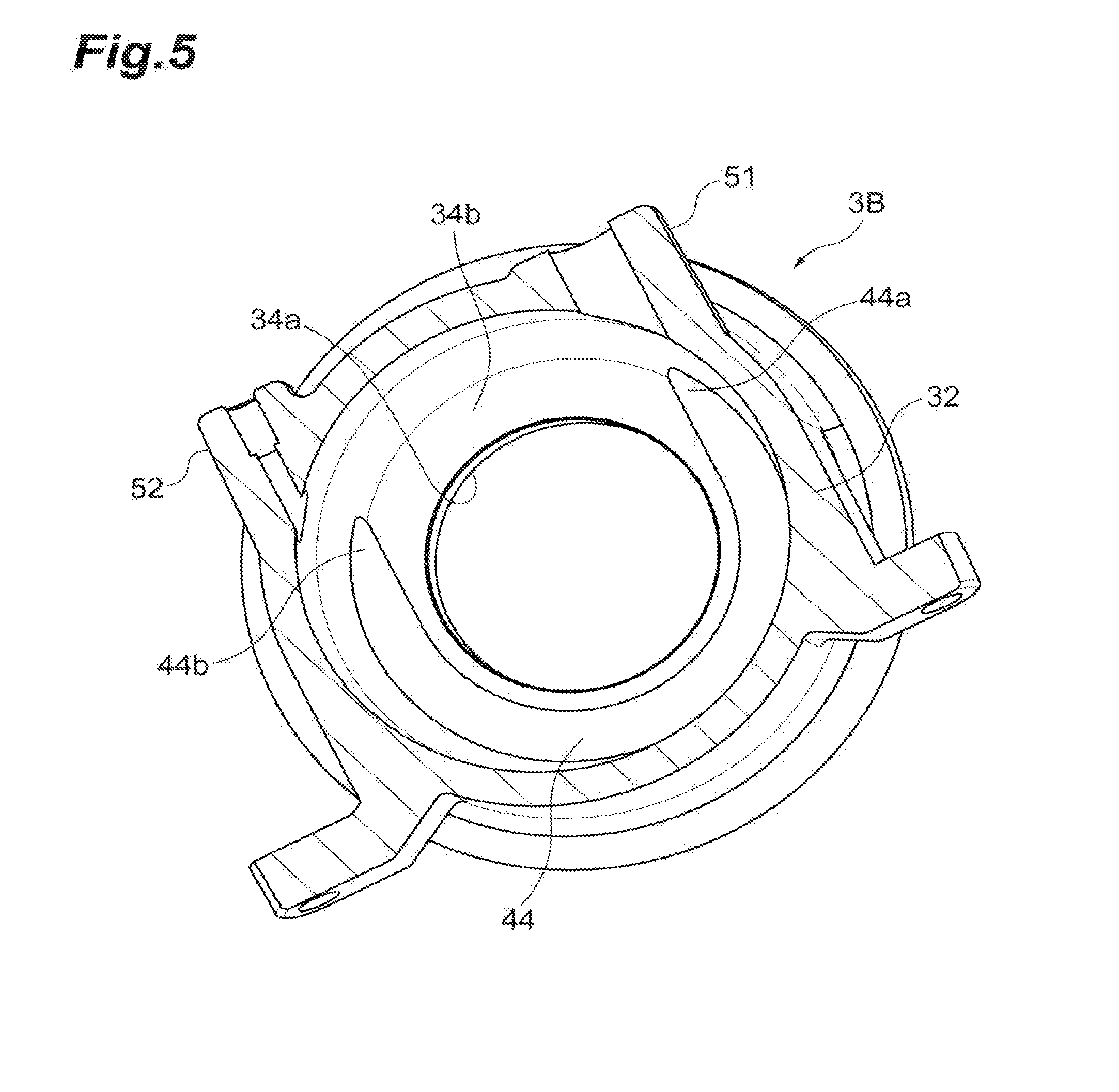
An electric compressor includes: a rotary shaft to which a compressor impeller is attached; a stator portion which is disposed around the rotary shaft; and a motor housing which accommodates the stator portion. The motor housing includes an inner housing which includes a first cylindrical portion surrounding and holding the stator portion and an outer housing which includes a second cylindrical portion surrounding and holding the first cylindrical portion of the inner housing. Between an outer surface of the inner housing and an inner surface of the outer housing, a cooling jacket portion is formed in a part of a circumferential direction about the rotary shaft. The inner housing includes a first end wall portion which is formed to be continuous to the first cylindrical portion and extends inward in relation to an outer peripheral portion of the stator portion in a radial direction of the rotary shaft.
| Inventors: | IIZUKA; Kuniaki; (Koto-ku, JP) ; YOSHIDA; Takashi; (Koto-ku, JP) ; SASAKI; Yuji; (Koto-ku, JP) ; INOMATA; Tatsumi; (Koto-ku, JP) ; OZASA; Takuya; (Koto-ku, JP) ; YUMOTO; Ryosuke; (Koto-ku, JP) ; MORI; Takashi; (Koto-ku, JP) | ||||||||||
| Applicant: |
|
||||||||||
|---|---|---|---|---|---|---|---|---|---|---|---|
| Assignee: | IHI Corporation Koto-ku JP |
||||||||||
| Family ID: | 62145597 | ||||||||||
| Appl. No.: | 16/340423 | ||||||||||
| Filed: | November 17, 2017 | ||||||||||
| PCT Filed: | November 17, 2017 | ||||||||||
| PCT NO: | PCT/JP2017/041525 | ||||||||||
| 371 Date: | April 9, 2019 |
| Current U.S. Class: | 1/1 |
| Current CPC Class: | F02B 33/40 20130101; F02B 39/00 20130101; F04D 29/584 20130101; F02B 39/10 20130101; F02B 39/005 20130101; F04D 25/06 20130101; H02K 9/19 20130101; F04D 29/059 20130101; F04D 29/5806 20130101; F04D 29/056 20130101 |
| International Class: | F04D 25/06 20060101 F04D025/06; F04D 29/059 20060101 F04D029/059; F04D 29/58 20060101 F04D029/58 |
Foreign Application Data
| Date | Code | Application Number |
|---|---|---|
| Nov 21, 2016 | JP | 2016-226091 |
Claims
1. An electric compressor comprising: a rotary shaft to which a compressor impeller is attached; a stator portion which is disposed around the rotary shaft; and a motor housing which accommodates the stator portion, wherein the motor housing includes an inner housing which includes a first cylindrical portion surrounding and holding the stator portion and an outer housing which includes a second cylindrical portion surrounding and holding the first cylindrical portion of the inner housing, wherein, between an outer surface of the inner housing and an inner surface of the outer housing, a cooling jacket portion is formed in a part of a circumferential direction about the rotary shaft, and wherein the inner housing includes a first end wall portion which is formed to be continuous to the first cylindrical portion and extends inward in relation to an outer peripheral portion of the stator portion in a radial direction of the rotary shaft.
2. The electric compressor according to claim 1, wherein the cooling jacket portion includes a first end portion and a second end portion which are an inlet and an outlet of a cooling fluid.
3. The electric compressor according to claim 1, wherein a contact plane in which the outer surface of the inner housing contacts the inner surface of the outer housing is formed between the outer surface of the inner housing and the inner surface of the outer housing, wherein at least one of the inner housing and the outer housing includes a recess portion which is recessed with respect to the contact plane and forms the cooling jacket portion, and wherein the recess portion of the inner housing or the outer housing is formed only in the part of the circumferential direction so that the cooling jacket portion is formed in the part of the circumferential direction.
4. The electric compressor according to claim 1, further comprising: a bearing which is provided inside the motor housing and supports the rotary shaft, wherein the first end wall portion of the inner housing includes an annular portion through which the rotary shaft penetrates and which surrounds the bearing and the annular portion holds the bearing.
5. The electric compressor according to claim 2, further comprising: a bearing which is provided inside the motor housing and supports the rotary shaft, wherein the first end wall portion of the inner housing includes an annular portion through which the rotary shaft penetrates and which surrounds the bearing and the annular portion holds the bearing.
6. The electric compressor according to claim 3, further comprising: a bearing which is provided inside the motor housing and supports the rotary shaft, wherein the first end wall portion of the inner housing includes an annular portion through which the rotary shaft penetrates and which surrounds the bearing and the annular portion holds the bearing.
Description
TECHNICAL FIELD
[0001] The present disclosure relates to an electric compressor.
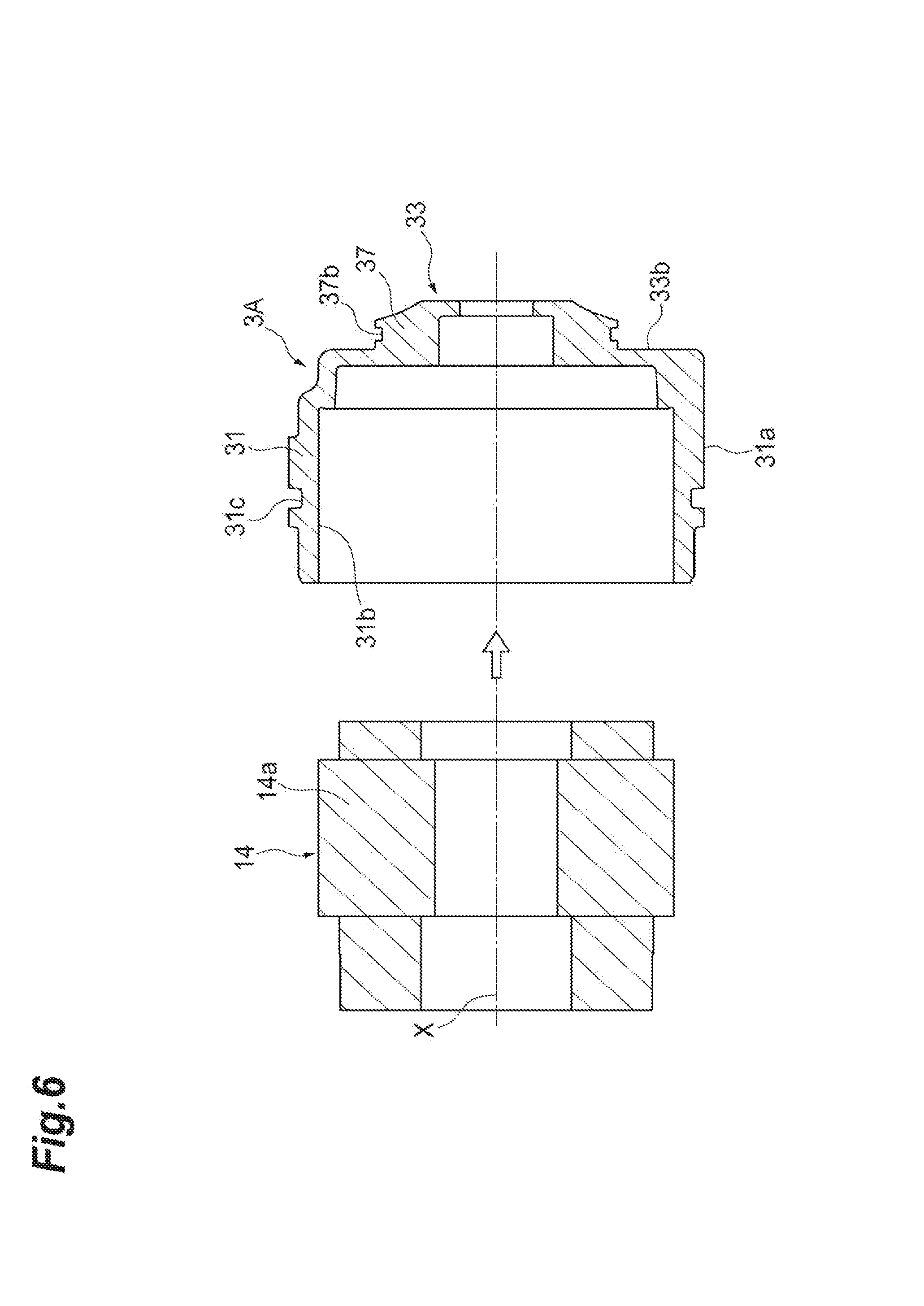
BACKGROUND ART
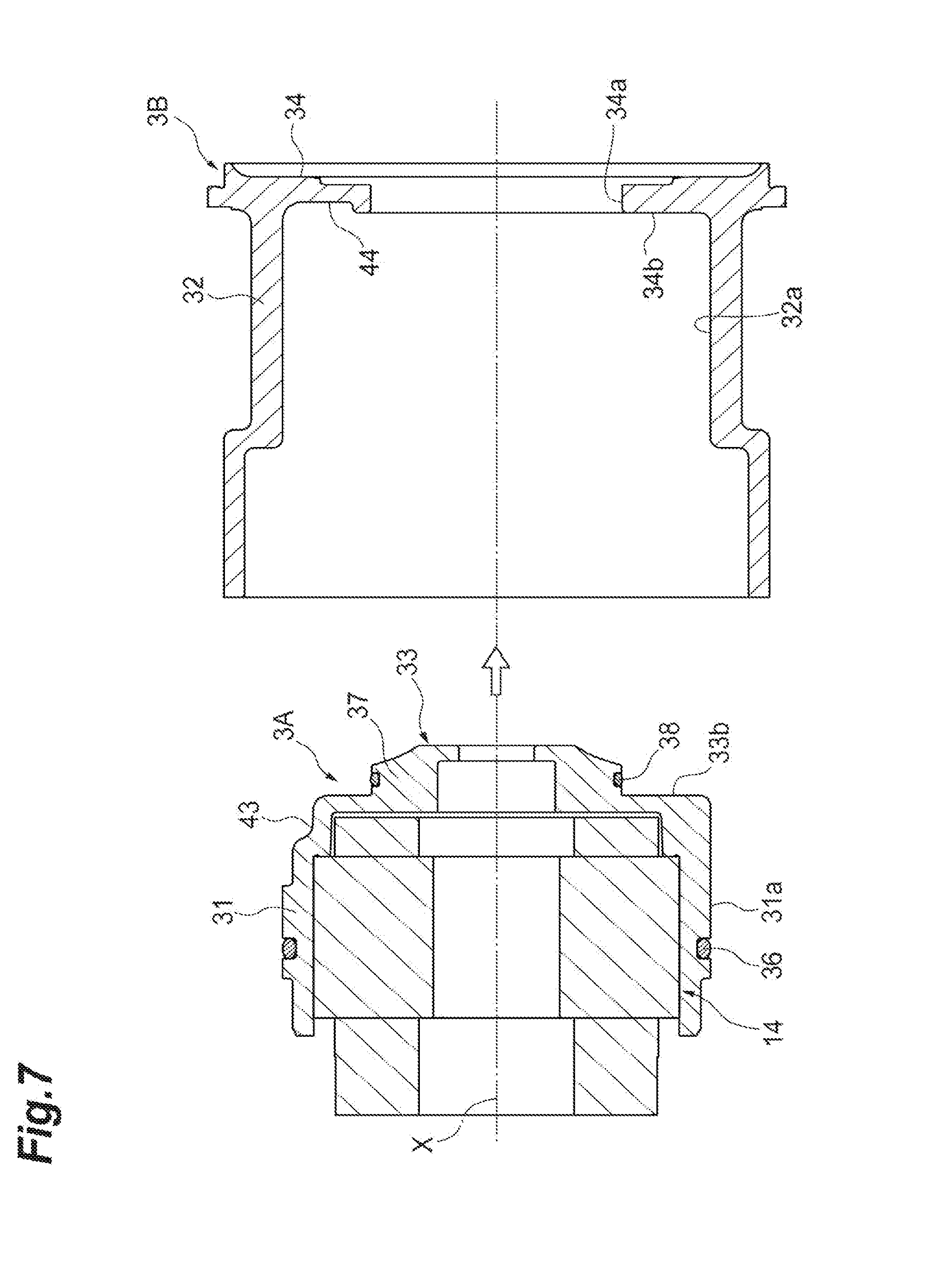
[0002] Conventionally, an electric supercharger disclosed in Patent Documents 1 and 2 is known. The electric supercharger includes a motor stator and a motor rotor. The electric supercharger described in Patent Document 1 includes a stator assembly in which a motor stator is integrated with an outer sleeve supporting the motor stator. A water cooling jacket is provided between an outer sleeve and a bearing housing. Also in the electric supercharger described in Patent Document 2, a space is provided around the motor stator.
CITATION LIST
Patent Literature
[0003] Patent Document 1: International Publication No. 2008/020512
[0004] Patent Document 2: Japanese Unexamined Patent Publication No. 2007-321698
SUMMARY OF INVENTION
Technical Problem
[0005] In the above-described conventional electric supercharger (electric compressor), the cooling of the stator portion is considered, but there are other elements that generate heat in the vicinity of a rotation body (a rotary shaft or the like) rotating together with a compressor impeller. Therefore, it is required to further improve cooling efficiency of the entire electric compressor. The present disclosure will describe an electric compressor capable of improving cooling efficiency.
Solution to Problem
[0006] An electric compressor according to an aspect of the present disclosure includes: a rotary shaft to which a compressor impeller is attached; a stator portion which is disposed around the rotary shaft; and a motor housing which accommodates the stator portion, in which the motor housing includes an inner housing which includes a first cylindrical portion surrounding and holding the stator portion and an outer housing which includes a second cylindrical portion surrounding and holding the first cylindrical portion of the inner housing, in which, between an outer surface of the inner housing and an inner surface of the outer housing, a cooling jacket portion is formed in a part of a circumferential direction about the rotary shaft, or over the entire circumference about the rotary shaft, and in which the inner housing includes a first end wall portion which is foiined to be continuous to the first cylindrical portion and extends inward in relation to an outer peripheral portion of the stator portion in a radial direction of the rotary shaft.
Effects of Invention
[0007] According to an aspect of the present disclosure, it is possible to improve cooling efficiency.
BRIEF DESCRIPTION OF DRAWINGS
[0008] FIG. 1 is a cross-sectional view illustrating a centrifugal compressor according to an embodiment of the present disclosure.
[0009] FIG. 2 is a cross-sectional view illustrating a motor housing of FIG. 1.
[0010] FIG. 3 is a cross-sectional view taken along a line III-III of FIG. 2.
[0011] FIG. 4 is a perspective view illustrating an inner housing of FIG. 1.
[0012] FIG. 5 is a perspective view illustrating an outer housing of FIG. 1.
[0013] FIG. 6 is a cross-sectional view illustrating a first step of an assembly process.
[0014] FIG. 7 is a cross-sectional view illustrating a second step of the assembly process.
DESCRIPTION OF EMBODIMENTS
[0015] An electric compressor according to an aspect of the present disclosure includes: a rotary shaft to which a compressor impeller is attached; a stator portion which is disposed around the rotary shaft; and a motor housing which accommodates the stator portion, in which the motor housing includes an inner housing which includes a first cylindrical portion surrounding and holding the stator portion and an outer housing which includes a second cylindrical portion surrounding and holding the first cylindrical portion of the inner housing, in which, between an outer surface of the inner housing and an inner surface of the outer housing, a cooling jacket portion is formed in a part of a circumferential direction about the rotary shaft, or over the entire circumference about the rotary shaft, and in which the inner housing includes a first end wall portion which is formed to be continuous to the first cylindrical portion and extends inward in relation to an outer peripheral portion of the stator portion in a radial direction of the rotary shaft.
[0016] According to the electric compressor, when a cooling fluid flows in the cooling jacket portion, a heating part (a motor or the like) of the electric compressor can be cooled through the inner housing. The stator portion can be cooled by the first cylindrical portion. In addition, the first end wall portion extends inward in relation to the outer peripheral portion of the stator portion in the radial direction. Not only the motor but also other heating parts around the rotary shaft can be cooled by the first end wall portion. Thus, it is possible to improve cooling efficiency.
[0017] In some aspects, the cooling jacket portion is formed in the part of the circumferential direction. The cooling jacket portion includes a first end portion and a second end portion which are an inlet and an outlet of a cooling fluid. In this case, the cooling fluid flows from the first end portion to the second end portion or from the second end portion to the first end portion. Since it is possible to suppress the stagnation or drift of the cooling fluid, cooling efficiency is further improved. The positions of the inlet and the outlet of the cooling fluid can be changed by the configuration of the peripheral device provided with the electric compressor, but such a change can be flexibly handled by appropriately changing the position of the cooling jacket portion (the positions of the first and second end portions).
[0018] In some aspects, a contact plane in which the outer surface of the inner housing contacts the inner surface of the outer housing is formed between the outer surface of the inner housing and the inner surface of the outer housing, at least one of the inner housing and the outer housing includes a recess portion which is recessed with respect to the contact plane and forms the cooling jacket portion, and the recess portion of the inner housing or the outer housing is formed only in the part of the circumferential direction so that the cooling jacket portion is formed in the part of the circumferential direction. In this case, the cooling jacket portion can be arbitrarily formed by appropriately changing the position (range) or size of the recess portion.
[0019] In some aspects, the electric compressor includes a bearing which is provided inside the motor housing and supports the rotary shaft and the first end wall portion of the inner housing includes an annular portion through which the rotary shaft penetrates and which surrounds the bearing and the annular portion holds the bearing. In this case, the bearing can be cooled through the annular portion of the first end wall portion. Not only the motor but also the bearing can be efficiently cooled.
[0020] Hereinafter, an embodiment of the present disclosure will be described with reference to the drawings. In the description of the drawings, the same elements are denoted by the same reference numerals and a redundant description is omitted. In the description below, the terms of the "radial direction" and the "circumferential direction" are used with reference to a rotary shaft 12 or a rotation axis X unless otherwise specified.
[0021] Referring to FIG. 1, an electric compressor 1 of a first embodiment will be described. As illustrated in FIG. 1, the electric compressor 1 is applied to, for example, an internal combustion engine of a vehicle or a ship. The electric compressor 1 includes a compressor 7. The electric compressor 1 rotates a compressor impeller 8 by the interaction of a rotor portion 13 and a stator portion 14 to compress a gas such as air and generate compressed air. The rotor portion 13 and the stator portion 14 constitute a motor 5.
[0022] The electric compressor 1 includes the rotary shaft 12 which is rotatably supported inside a housing 2 and the compressor impeller 8 which is attached to a front end portion of the rotary shaft 12. The housing 2 includes a motor housing 3 which accommodates the rotor portion 13 and the stator portion 14, an inverter housing 4 which closes an opening of a second end side (the left side of the drawing) of the motor housing 3 and a compressor housing 6 which accommodates the compressor impeller 8. The compressor housing 6 is provided at a first end side (the right side of the drawing) of the motor housing 3. The compressor housing 6 includes a suction port 9, a scroll portion 10, and a discharge port 11.
[0023] The rotor portion 13 is fixed to a center portion of the rotary shaft 12 in the direction of the rotation axis X and includes one or plural permanent magnets (not illustrated) attached to the rotary shaft 12. The stator portion 14 is held by the inner surface of the motor housing 3 to surround the rotor portion 13. That is, the stator portion 14 is disposed around the rotary shaft 12. The stator portion 14 includes a cylindrical core portion 14a which is disposed to surround the rotor portion 13 and a coil portion 14b which is formed by winding a conductive wire (not illustrated) around the core portion 14a. When an AC current flows to the coil portion 14b of the stator portion 14 through the conductive wire, the rotary shaft 12 and the compressor impeller 8 rotate together by the interaction of the rotor portion 13 and the stator portion 14. When the compressor impeller 8 rotates, the compressor impeller 8 sucks external air through the suction port 9, compresses the air through the scroll portion 10, and discharges the compressed air from the discharge port 11. The compressed air discharged from the discharge port 11 is supplied into the above-described internal combustion engine.
[0024] The electric compressor 1 includes two bearings 20A and 20B which rotatably support the rotary shaft 12 with respect to the housing 2. The bearings 20A and 20B are provided inside the motor housing 3. The bearings 20A and 20B are disposed with the motor 5 interposed therebetween and support the rotary shaft 12 at both ends thereof The first bearing 20A is held by an annular portion 37 provided at an end portion on the side of the compressor impeller 8 in the motor housing 3. The second bearing 20B is held by the inner surface side (the side of the compressor impeller 8) of the partition wall portion 4a of the inverter housing 4.
[0025] Next, a configuration of the motor housing 3 will be described in more detail with reference to FIGS. 1 and 2. The motor housing 3 includes a cylindrical inner housing 3A which is disposed at the inside, that is, the side of the rotary shaft 12 and a cylindrical outer housing 3B which is disposed at the outside, that is, the outer peripheral side of the inner housing 3A. That is, the motor housing 3 has a structure divided into two parts. The inner housing 3A and the outer housing 3B are separate members and are arranged concentrically with respect to the rotation axis X. The inner housing 3A is attached to the outer housing 3B by, for example, tightening fitting (shrink fitting or the like).
[0026] The inner housing 3A surrounds and holds the stator portion 14. The stator portion 14 is attached to the inner housing 3A by, for example, shrink fitting or press inserting. Accordingly, the inner housing 3A and the stator portion 14 are unitized. The outer housing 3B surrounds and holds the inner housing 3A. The inner housing 3A and the stator portion 14 which are unitized are attached to the outer housing 3B by, for example, tightening fitting (shrink fitting or the like).
[0027] The inner housing 3A includes a first cylindrical portion 31 which has a cylindrical shape and extends in the direction of the rotation axis X and a first end wall portion 33 which is formed to be continuous to a first end side (the side of the compressor impeller 8) of the first cylindrical portion 31. The first cylindrical portion 31 surrounds and holds the stator portion 14. A second end (an opposite side to the first end wall portion 33) of the first cylindrical portion 31 is opened. The first end wall portion 33 extends inward in the radial direction from the first end of the first cylindrical portion 31 (see FIGS. 4 and 6).
[0028] The first end wall portion 33 includes the annular portion 37 which is provided at the center side, that is, the side of the rotation axis X. The annular portion 37 protrudes in the direction of the rotation axis X (the side of the compressor impeller 8) in relation to the first end of the first cylindrical portion 31. An annular outer surface 33b is formed around the annular portion 37. The outer surface 33b is a shoulder portion which is provided between the first cylindrical portion 31 and the annular portion 37. The outer surface 33b is a flat surface which extends in a direction perpendicular to the rotation axis X. The annular portion 37 is disposed around the rotation axis X. A through-hole 37d is provided at the center of the annular portion 37. A boss portion 8b of the compressor impeller 8 and the rotary shaft 12 are inserted through the through-hole 37d and the rotary shaft 12 penetrates the annular portion 37.
[0029] As illustrated in FIG. 1, the annular portion 37 extends inward in relation to the outer peripheral portion of the stator portion 14 in the radial direction. The annular portion 37 surrounds the first bearing 20A. The annular portion 37 includes a cylindrical bearing accommodation portion which is continuous to the through-hole 37d and holds the first bearing 20A in the inner peripheral surface 37c.
[0030] The outer housing 3B includes a second cylindrical portion 32 which has a cylindrical shape and extends in the direction of the rotation axis X and a second end wall portion 34 which is provided to be continuous to the first end of the second cylindrical portion 32. The second cylindrical portion 32 surrounds and holds the first cylindrical portion 31 of the inner housing 3A. The second end of the second cylindrical portion 32 is opened. The second end wall portion 34 extends inward in the radial direction from the first end of the second cylindrical portion 32. As illustrated in FIGS. 2, 5, and 7, the second end wall portion 34 is formed in an annular shape and is disposed around the rotation axis X. An inner surface 34b of the second end wall portion 34 in the radial direction is a flat surface which extends in a direction perpendicular to the rotation axis X. An opening is formed at the center of the second end wall portion 34 and the annular portion 37 of the inner housing 3A is disposed inside the opening. As illustrated in FIG. 1, the annular portion 37 and the first bearing 20A are disposed inside the opening of the second end wall portion 34.
[0031] As illustrated in FIGS. 2 and 7, the inner housing 3A is inserted from the second end side of the outer housing 3B and is fitted into the outer housing 3B. The inner housing 3A is fitted into the outer housing 3B while holding the stator portion 14. An outer peripheral surface 31a of the first cylindrical portion 31 comes into contact with an inner peripheral surface 32a of the second cylindrical portion 32. The outer peripheral surface 31a may be in close contact with the inner peripheral surface 32a. A first contact plane S1 having a cylindrical shape is formed by the outer peripheral surface 31a and the inner peripheral surface 32a. A first seal member 36 having an annular shape is formed between the outer peripheral surface 31a and the inner peripheral surface 32a. The first seal member 36 is provided in one seal groove 31c (see FIG. 6) formed in the outer peripheral surface 31a of the first cylindrical portion 31. The first seal member 36 is, for example, an O-ring.
[0032] The outer surface 33b of the first end wall portion 33 comes into contact with the inner surface 34b of the second end wall portion 34. The outer surface 33b may abut against the inner surface 34b. A second contact plane 52 having a flat annular shape is formed by the outer surface 33b and the inner surface 34b. An outer peripheral surface 37a of the annular portion 37 comes into contact with an inner peripheral surface 34a of the second end wall portion 34. The first end wall portion 33 and the second end wall portion 34 face a back surface 8a of the compressor impeller 8 with a slight gap therebetween (see FIG. 1). The outer peripheral surface 37a may be in close contact with the inner peripheral surface 34a. A second seal member 38 having an annular shape is provided between the outer peripheral surface 37a and the inner peripheral surface 34a. The second seal member 38 is provided in one seal groove 37b (see FIG. 6) formed in the outer peripheral surface 37a of the annular portion 37. The second seal member 38 is, for example, an O-ring.
[0033] The inner housing 3A and the outer housing 3B may be held at any one of the outer peripheral surface 31a and the inner peripheral surface 32a or the outer peripheral surface 37a and the inner peripheral surface 34a. The outer peripheral surface 31a and the inner peripheral surface 32a may be connected to each other by tightening fitting (shrink fitting or the like) and the outer peripheral surface 37a and the inner peripheral surface 34a may be fitted to each other with a gap therebetween. In contrast, the outer peripheral surface 31a and the inner peripheral surface 32a may be fitted to each other with a gap therebetween and the outer peripheral surface 37a and the inner peripheral surface 34a may be connected to each other by tightening fitting (shrink fitting or the like). A gap may be formed between the outer peripheral surface 37a and the inner peripheral surface 34a fitted to each other with a gap therebetween or the outer peripheral surface 31a and the inner peripheral surface 32a fitted to each other with a gap therebetween. Due to an assembling operation by tightening fitting, for example, the inner housing 3A is easily aligned to the outer housing 3B.
[0034] The inner housing 3A and the outer housing 3B are formed of the same material. The inner housing 3A and the outer housing 3B are formed of, for example, aluminum. As described above, the inner housing 3A is attached into the outer housing 3B by, for example, shrink fitting. In the assembly, the assembling operation can be performed by heating only the outer housing 3B. If the inner housing 3A and the outer housing 3B are formed of the same material, even when both housings are thermally expanded in use, the tightening margin substantially does not change.
[0035] The inner housing 3A and the outer housing 3B can be respectively manufactured by, for example, die casting or the like. Since the inner housing 3A and the outer housing 3B are molded by a method not using a core, both housings can be simply manufactured. Furthermore, when the inner housing 3A and the outer housing 3B are manufactured by die casting or the like, a draft angle is formed in the inner peripheral surface 32a of the outer housing 3B. Depending on the shape of the die, a draft angle is formed in the outer peripheral surface 31a of the inner housing 3A. In order to easily fit the inner housing 3A and the outer housing 3B to each other, machining may be performed on the inner peripheral surface 32a of the outer housing 3B and/or the outer peripheral surface 31a of the inner housing 3A to remove a draft angle.
[0036] The electric compressor 1 of the embodiment has a structure for cooling components provided inside the motor housing 3 through the motor housing 3. As illustrated in FIGS. 1 and 2, a water cooling jacket portion 40 for circulating a cooling fluid such as cooling water is formed between the inner surface of the outer housing 3B (the inner peripheral surface 32a and the inner surface 34b) and the outer surface of the inner housing 3A (the outer peripheral surface 31a and the outer surface 33b).
[0037] As illustrated in FIG. 3, the water cooling jacket portion 40 is formed only in a part in the circumferential direction. As illustrated in FIGS. 3 to 5, the water cooling jacket portion 40 is obtained by respectively fowling the recess portion 43 and the recess portion 44 in the inner housing 3A and the outer housing 3B and combining these members. In other words, the water cooling jacket portion 40 is a space which is surrounded between the recess portion 43 and the recess portion 44.
[0038] As illustrated in FIGS. 3 and 5, the inner surface 34b of the outer housing 3B is provided with the recess portion 44 which is recessed with respect to the second contact plane S2. The recess portion 44 extends in the circumferential direction and is formed only in the part in the circumferential direction. In other words, the recess portion 44 has a rotationally asymmetric shape with respect to the rotation axis X. The recess portion 44 may be provided in a rage equal to or larger than 180.degree. and smaller than 360.degree.. The recess portion 44 includes a first end portion 44a and a second end portion 44b. A portion not provided with the recess portion 44, that is, a portion between the first end portion 44a and the second end portion 44b (a range larger than 0.degree. and smaller than 180.degree.) is provided with the flat inner surface 34b forming the second contact plane S2.
[0039] As illustrated in FIG. 4, a continuous portion between the first cylindrical portion 31 and the first end wall portion 33 in the inner housing 3A is provided with the recess portion 43 which is recessed with respect to the first contact plane S1 and the second contact plane S2. The recess portion 43 extends in the circumferential direction and is formed only in the part of the circumferential direction. In other words, the recess portion 43 has a rotationally asymmetric shape with respect to the rotation axis X. The recess portion 43 may be formed in a range equal to or larger than 180.degree. and smaller than 360.degree.. The recess portion 43 includes a first end portion 43a and a second end portion 43b. A portion not provided with the recess portion 43, that is, a portion between the first end portion 43a and the second end portion 43b (a range larger than 0.degree. and smaller than 180.degree.) is provided with the outer peripheral surface 31a and the outer surface 33b which form the first contact plane S1 and the second contact plane S2.
[0040] The recess portion 43 may be formed in a range corresponding to the recess portion 44. In a state in which the inner housing 3A is attached to the outer housing 3B, the recess portion 43 is combined with the recess portion 44 (to communicate with each other). The position of the first end portion 44a may substantially match the position of the first end portion 43a. The position of the second end portion 44b may substantially match the position of the second end portion 43b. The water cooling jacket portion 40 has a rotationally asymmetric shape with respect to the rotation axis X. The water cooling jacket portion 40 includes a first end portion 41 which is formed by the first end portion 43a and the first end portion 44a and a second end portion 42 which is formed by the second end portion 43b and the second end portion 44b. An installation range of the water cooling jacket portion 40 or a shape of the water cooling jacket portion 40 can be appropriately changed by changing the ranges of forming the recess portion 43 and the recess portion 44 or the shapes of the recess portion 43 and the recess portion 44. The recess portion 43 and the recess portion 44 can be easily formed according to die casting.
[0041] The water cooling jacket portion 40 faces the outer peripheral surface 31a and the outer surface 33b of the inner housing 3A. Thus, a cooling fluid cools the first cylindrical portion 31 and the first end wall portion 33 (including the annular portion 37). It is possible to cool components installed inside the motor housing 3 and capable of generating heat by the first cylindrical portion 31 and the first end wall portion 33 which are cooled.
[0042] As illustrated in FIGS. 3 and 5, the outer housing 3B may be provided with an inflow pipe 51 and an outflow pipe 52 which are respectively connected to the first end portion 43 a and the second end portion 43b of the inner housing 3A. The inflow pipe 51 and the outflow pipe 52 are connected to an external pipe and a pump so that a cooling fluid is circulated therein.
[0043] Referring to FIGS. 6 and 7, an assembly method of the motor housing 3 will be described. As illustrated in FIG. 6, the stator portion 14 is attached to the inner housing 3A by shrink fitting or press inserting. At this time, the stator portion 14 is inserted in the direction of the rotation axis X from the second end side of the inner housing 3A (the left side of the drawing). Accordingly, the inner housing 3A and the stator portion 14 are unitized.
[0044] As illustrated in FIG. 7, the first seal member 36 and the second seal member 38 are respectively attached to the seal groove 31c and the seal groove 37b of the inner housing 3A. The inner housing 3A and the stator portion 14 which are unitized are attached to the outer housing 3B by shrink fitting. At this time, the inner housing 3A is inserted in the direction of the rotation axis X from the second end side of the outer housing 3B (the left side of the drawing). By the above-described process, it is possible to obtain a unit from the motor housing 3 and the stator portion 14.
[0045] According to the electric compressor 1 of the embodiment, when a cooling fluid flows in the water cooling jacket portion 40, a heating part (the motor 5 or the like) of the electric compressor 1 can be cooled through the inner housing 3A. The stator portion 14 can be cooled by the first cylindrical portion 31. In addition, the first end wall portion 33 extends inward in relation to the outer peripheral portion of the stator portion 14 in the radial direction. By the first end wall portion 33, not only the motor but also other peripheral heating parts of the rotary shaft 12 can be cooled. Thus, it is possible to improve cooling efficiency.
[0046] Conventionally, a motor housing with a cooling jacket portion was manufactured by a method such as casting using a core. Since it was difficult to manufacture the motor housing by die casting, a manufacturing cost was high. Further, since it was necessary to manufacture the whole motor housing against differences in compatibility and compressor specification, improvement was desired from the viewpoint of component commonality. According to the electric compressor 1 of the embodiment, the motor housing 3 includes the inner housing 3A and the outer housing 3B. In other words, the motor housing 3 is divided into the inner housing 3A and the outer housing 3B. By assembling these housings, the water cooling jacket portion 40 is formed. Further, the first seal member 36 and the second seal member 38 are provided at the front and rear sides of the water cooling jacket portion 40 and a water cooling mechanism is provided. Since a portion in which the inner housing 3A and the outer housing 3B abut against each other is provided with the recess portions 43 and 44 having a rotationally asymmetric shape, a water channel shape corresponding to the inlet/outlet position of the cooling fluid is realized. Further, the outer shape of the outer housing 3B may be changed against differences of the shape of the compressor impeller 8, the shape of the inverter housing 4 or the compressor housing 6, or the mounting boss. There is no need to change the inner housing 3A and the inner surface side of the outer housing 3B and a common configuration may be employed.
[0047] Further, since the motor housing 3 is divided into the inner housing 3A and the outer housing 3B, the water cooling jacket portion 40 does not become a closed space when manufacturing each housing and hence a core is not necessary. For this reason, the motor housing can be manufactured by die casting or the like. Since the inner housing 3A and the outer housing 3B are molded by a manufacturing method such as die casting not using a core, the motor housing is easily manufactured. In the assembly of the outer housing 3B and the inner housing 3A, these housings can be assembled just by heating the outer housing 3B. Although the inner housing 3A and the outer housing 3B can be thermally expanded in a use state, a tightening margin substantially does not change when both housings are formed of the same material. For this reason, the outer housing 3B can reliably hold the inner housing 3A in a use state.
[0048] Further, since the first seal member 36 and the second seal member 38 are provided at the front and rear sides of the water cooling jacket portion 40, a structure that prevents the leakage of the cooling fluid to the outside is obtained. By changing the shape of the abutting portion, a flow passage range in the circumferential direction can be changed. Thus, it is possible to secure the flexibility of the inlet/outlet position of the cooling fluid.
[0049] In the water cooling jacket portion 40 having a rotationally asymmetric shape, the cooling fluid flows from the first end portion 41 to the second end portion 42. Since it is possible to suppress the stagnation or drift of the cooling fluid as compared with a case in which the water cooling jacket portion is provided in the entire circumference, cooling efficiency is further improved. The positions of the inlet and the outlet of the cooling fluid can be changed depending on the configuration of the peripheral device provided with the electric compressor 1, but when the position of the water cooling jacket portion 40 (the positions of the first end portion 41 and the second end portion 42) is appropriately changed, such a change can be also flexibly handled.
[0050] By appropriately changing the positions (ranges) or sizes of the recess portions 43 and 44, it is possible to form the water cooling jacket portion 40 into an arbitrary shape.
[0051] According to the annular portion 37 which holds the first bearing 20A, it is possible to efficiently cool not only the motor 5 but also the first bearing 20A.
[0052] Although the embodiments of the present disclosure have been described, the present disclosure is not limited to the above-described embodiments. For example, the second end wall portion of the outer housing 3B may not extend inward in relation to the outer peripheral portion of the stator portion 14. The second end wall portion of the outer housing 3B may be omitted. The first end wall portion of the inner housing 3A may face the entire surface of the back surface 8a of the compressor impeller 8.
[0053] The water cooling jacket portion 40 may be formed by at least one of the recess portion 43 and the recess portion 44. The present disclosure is not limited to a case in which the water cooling jacket portion 40 is formed only by the recess portions 43 and 44. The water cooling jacket portion 40 may be formed by the recess portions 43 and 44 provided in the entire circumference and a partition member separated from the inner housing 3A or the outer housing 3B may be provided in a part of the water cooling jacket portion 40. The partition member is provided inside the water cooling jacket portion 40 and can define a flow passage shape.
[0054] The water cooling jacket portion may be formed in the entirety (that is, the entire circumference) of the circumferential direction. The cooling fluid is not limited to water and may be other liquids such as oil. The present disclosure may be applied to an electric compressor with a turbine.
INDUSTRIAL APPLICABILITY
[0055] According to some aspects of the present disclosure, it is possible to improve cooling efficiency.
REFERENCE SIGNS LIST
[0056] 1: electric compressor, 2: housing, 3: motor housing, 3A: inner housing, 3B: outer housing, 4: inverter housing, 4a: partition wall portion, 5: motor, 6: compressor housing, 8: compressor impeller, 8a: back surface, 12: rotary shaft, 14: stator portion, 20A: first bearing, 20B: second bearing, 31: first cylindrical portion, 31a: outer peripheral surface (outer surface), 32: second cylindrical portion, 32a: inner peripheral surface (inner surface), 33: first end wall portion, 33b: outer surface, 34: second end wall portion, 34a: inner peripheral surface, 34b: inner surface, 36: first seal member, 37: annular portion, 37a: outer peripheral surface, 38: second seal member, 40: water cooling jacket portion (cooling jacket portion), 41: first end portion, 42: second end portion, 43: recess portion, 44: recess portion, S1: first contact plane, S2: second contact plane, X: rotation axis.
* * * * *
D00000
D00001
D00002
D00003
D00004
D00005
D00006
D00007
XML
uspto.report is an independent third-party trademark research tool that is not affiliated, endorsed, or sponsored by the United States Patent and Trademark Office (USPTO) or any other governmental organization. The information provided by uspto.report is based on publicly available data at the time of writing and is intended for informational purposes only.
While we strive to provide accurate and up-to-date information, we do not guarantee the accuracy, completeness, reliability, or suitability of the information displayed on this site. The use of this site is at your own risk. Any reliance you place on such information is therefore strictly at your own risk.
All official trademark data, including owner information, should be verified by visiting the official USPTO website at www.uspto.gov. This site is not intended to replace professional legal advice and should not be used as a substitute for consulting with a legal professional who is knowledgeable about trademark law.