Pumps
STOKKEV G; Terje ; et al.
U.S. patent application number 16/254688 was filed with the patent office on 2019-07-25 for pumps. The applicant listed for this patent is IMPACT SOLUTIONS AS. Invention is credited to Oddgeir HUSOY, Geir Kvalsund Sandnes, Terje STOKKEV G.
| Application Number | 20190226477 16/254688 |
| Document ID | / |
| Family ID | 65657496 |
| Filed Date | 2019-07-25 |


| United States Patent Application | 20190226477 |
| Kind Code | A1 |
| STOKKEV G; Terje ; et al. | July 25, 2019 |
PUMPS
Abstract
According to an embodiment, a pump includes a power end, and a fluid end. A sliding plate extends from the power end, and a distal end of the sliding plate has engaging structure. The fluid end has complementary engaging structure for slidably mating with the engaging structure as the fluid end is raised or lowered relative to the power end. A locking plate is provided for preventing disengagement of the complementary engaging structure and the engaging structure.
| Inventors: | STOKKEV G; Terje; (Ulsteinvik, NO) ; HUSOY; Oddgeir; (Fosnavaag, NO) ; Sandnes; Geir Kvalsund; (Tjoervaag, NO) | ||||||||||
| Applicant: |
|
||||||||||
|---|---|---|---|---|---|---|---|---|---|---|---|
| Family ID: | 65657496 | ||||||||||
| Appl. No.: | 16/254688 | ||||||||||
| Filed: | January 23, 2019 |
Related U.S. Patent Documents
| Application Number | Filing Date | Patent Number | ||
|---|---|---|---|---|
| 62621125 | Jan 24, 2018 | |||
| Current U.S. Class: | 1/1 |
| Current CPC Class: | F04B 53/22 20130101; F04B 53/16 20130101 |
| International Class: | F04B 53/16 20060101 F04B053/16 |
Claims
1. A pump, comprising: a power end; a sliding plate extending from the power end, a distal end of the sliding plate having engaging structure; a fluid end having complementary engaging structure for slidably mating with the engaging structure as the fluid end is raised or lowered relative to the power end; and a locking plate for preventing disengagement of the complementary engaging structure and the engaging structure.
2. The pump of claim 1, wherein the locking plate includes a fastener interacting with the fluid end, the fastener being axially offset angularly from a direction of sliding engagement between the complementary engaging structure and the engaging structure.
3. The pump of claim 1, wherein the power end has a crank shaft.
4. The pump of claim 1, wherein the power end is hydraulic.
5. The pump of claim 1, wherein the engaging structure has a generally circular cross-section.
6. The pump of claim 1, wherein the engaging structure is vertically oriented along a height of the sliding plate.
7. The pump of claim 6, wherein the engaging structure has a generally circular cross-section.
8. The pump of claim 6, wherein the height of the sliding plate is substantially similar to a height of the fluid end.
9. The pump of claim 8, wherein the engaging structure interacts with the complementary engaging structure over a distance that is at least fifty percent as long as the height of the fluid end.
10. The pump of claim 8, wherein the engaging structure interacts with the complementary engaging structure over a distance that is at least eighty percent as long as the height of the fluid end.
11. The pump of claim 8, wherein the engaging structure interacts with the complementary engaging structure over a distance that is at least ninety percent as long as the height of the fluid end.
12. The pump of claim 1, wherein the sliding plates are formed unitary with the power end.
13. The pump of claim 1, wherein the fluid end further comprises a stop to limit the sliding of the fluid end relative to the sliding plates.
14. A pump, comprising: a power end; a first plate extending from the power end, a distal end of the plate having engaging structure; a fluid end having complementary engaging structure for mating with the engaging structure as the fluid end is joined to the power end; and a suction manifold positioned to automatically engage with the fluid end when the fluid end is moved into an operating position.
15. The pump of claim 14, wherein the engaging structure is vertically oriented along a height of the first plate, and wherein the height of the first plate is substantially equal to a height of the fluid end.
16. The pump of claim 15, wherein the engaging structure has a generally circular cross-section.
17. The pump of claim 16, wherein the engaging structure interacts with the complementary engaging structure over a distance that is at least fifty percent as long as the height of the fluid end.
18. The pump of claim 14, further comprising a second plate extending from the power end, the second plate being devoid of engaging structure, wherein the second plate is removably fastened to the fluid end to prevent disengagement of the complementary engaging structure and the engaging structure.
19. A method of engaging a power end of a pump with a fluid end of the pump, comprising: providing a power end, comprising: a sliding plate extending from the power end, a distal end of the sliding plate having engaging structure vertically oriented along a height of the sliding plate and having a generally circular cross-section; and a locking plate extending from the power end; providing a fluid end, comprising complementary engaging structure for mating with the engaging structure of the power end; positioning the fluid end such that the complementary engaging structure aligns with the engaging structure of the power end; lowering the fluid end into an operating position, wherein in the operating position, the fluid end slidably mates with the power end and automatically engages a suction manifold; and installing the locking plate to the fluid end.
20. The pump of claim 19, wherein the fluid end further comprises a stop to limit the sliding of the fluid end relative to the sliding plates.
Description
CROSS-REFERENCE TO RELATED APPLICATION
[0001] This application claims priority to U.S. Provisional Patent Application No. 62/621,125 filed Jan. 24, 2018, the disclosure of which is incorporated by reference herein in its entirety.
FIELD OF THE INVENTION
[0002] This application relates to pumps, and more specifically, to pumps having a unique slide-in, slide-out feature.
SUMMARY OF THE INVENTION
[0003] The following presents a simplified summary of the invention in order to provide a basic understanding of some aspects of the invention. The summary is not an extensive overview of the invention. It is not intended to identify critical elements of the invention or to delineate the scope of the invention. Its sole purpose is to present some aspects of the invention in a simplified form as a prelude to the more detailed description that is presented elsewhere herein.
[0004] According to an embodiment of the invention, a pump includes a power end, and a fluid end. A sliding plate extends from the power end, and a distal end of the sliding plate has engaging structure. The fluid end has complementary engaging structure for slidably mating with the engaging structure as the fluid end is raised or lowered relative to the power end. A locking plate is provided for preventing disengagement of the complementary engaging structure and the engaging structure.
[0005] According to another embodiment of the invention, a pump includes a power end and a fluid end. A first plate extends from the power end, and a distal end of the plate has engaging structure. The fluid end has complementary engaging structure for mating with the engaging structure as the fluid end is joined to the power end. A suction manifold is positioned to automatically engage with the fluid end when the fluid end is moved into an operating position.
[0006] According to still another embodiment of the invention, a method of engaging a power end of a pump with a fluid end of the pump is provided. According to the method, a power end is provided, which includes a sliding plate extending from the power end, wherein a distal end of the sliding plate has engaging structure vertically oriented along a height of the sliding plate and has a generally circular cross-section. A locking plate also extends from the power end. The method further includes providing a fluid end, which has complementary engaging structure for mating with the engaging structure of the power end. The fluid end is positioned such that the complementary engaging structure aligns with the engaging structure of the power end, and is subsequently lowered into an operating position. In the operating position, the fluid end slidably mates with the power end and automatically engages a suction manifold. Finally, the locking plate is fastened to the fluid end.
BRIEF DESCRIPTION OF THE DRAWINGS
[0007] FIG. 1A is a perspective view of a PRIOR ART pump.
[0008] FIG. 1B is an end view of the PRIOR ART pump of FIG. 1A.
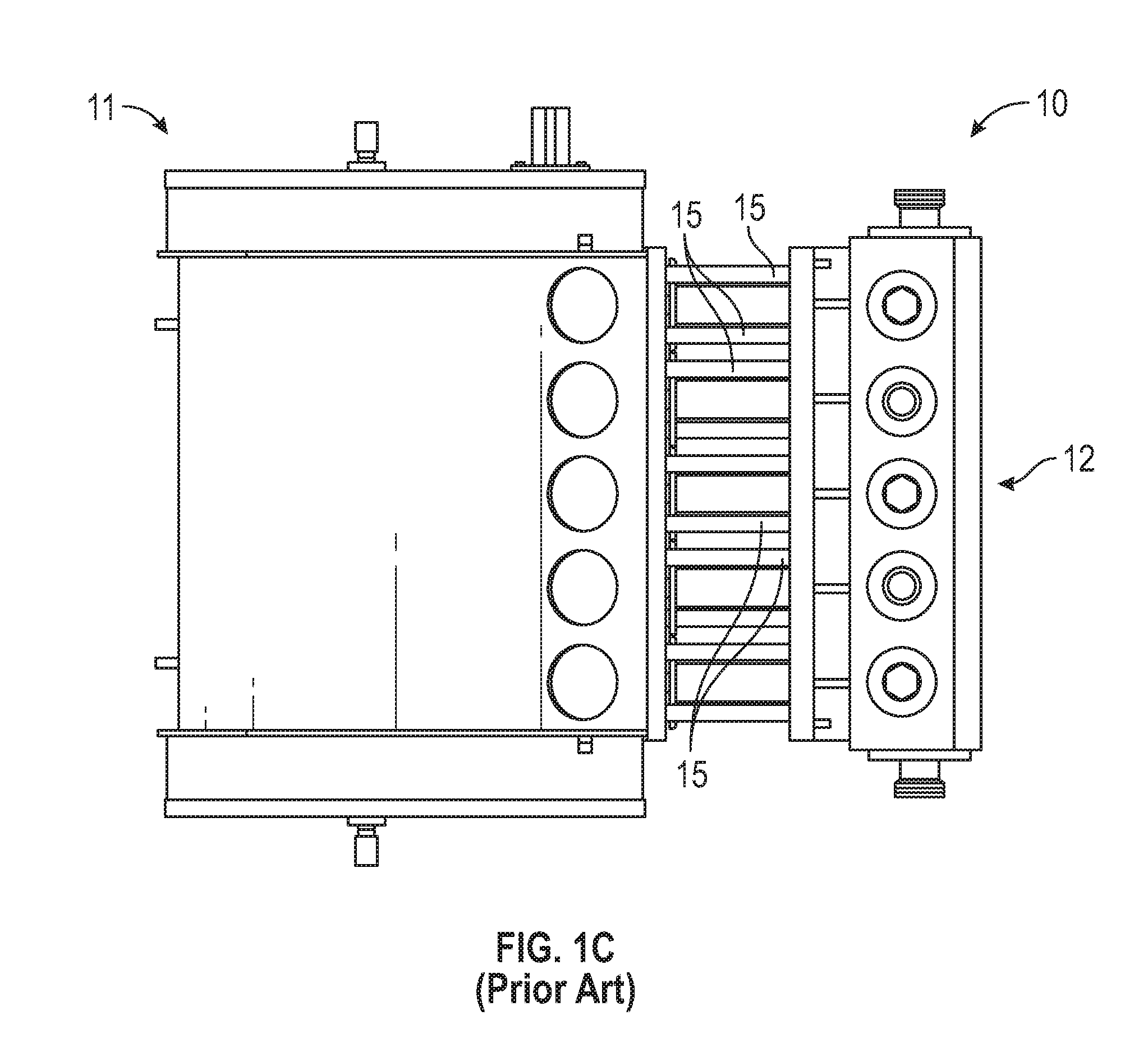
[0009] FIG. 1C is a top view of the PRIOR ART pump of FIG. 1A.
[0010] FIG. 2 is a perspective view of a pump according to an embodiment of the current invention.
[0011] FIG. 3 is a perspective view of the pump of FIG. 2, shown with a fluid end of the pump removed.
[0012] FIG. 4 is a sectional view of the pump of FIG. 2.
[0013] FIG. 5 is a side view of the pump of FIG. 2.
[0014] FIG. 6 is a sectional view of the pump of FIG. 2, taken along line C-C in FIG. 5.
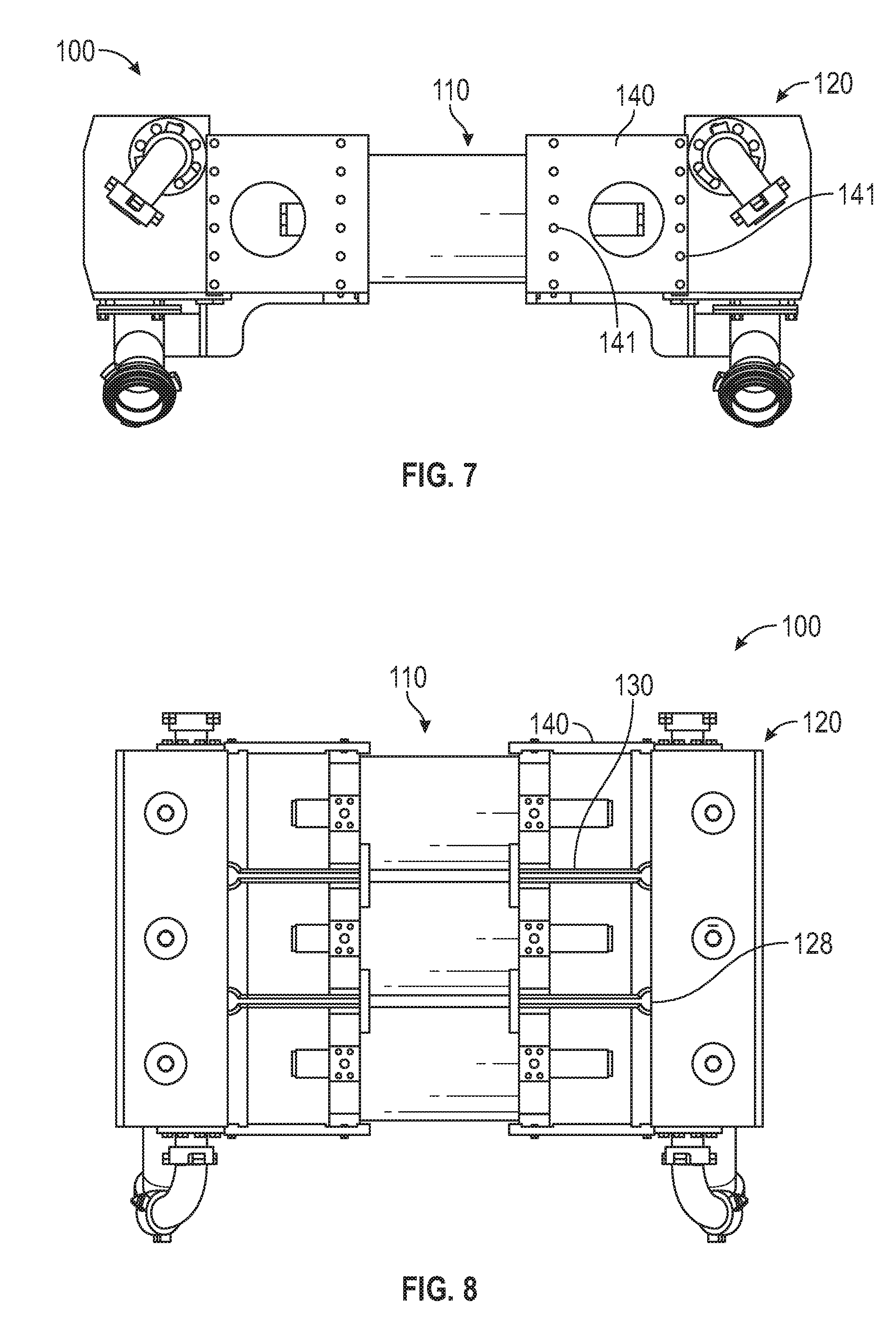
[0015] FIG. 7 is an end view of the pump of FIG. 2.
[0016] FIG. 8 is a top view of the pump of FIG. 2.
[0017] FIGS. 9 through 12 are exploded views of the pump of FIG. 2.
[0018] FIG. 13 is a perspective view of a pump according to another embodiment of the current invention.
[0019] FIG. 14 is still another perspective view of a pump according to still another embodiment of the invention.
DETAILED DESCRIPTION
[0020] FIGS. 1A through 1C show a PRIOR ART pump 10 having a power end 11 and a fluid end 12. The power end 11 contains a crank shaft converting rotational forces (e.g., from a diesel engine or another power source) into reciprocating forces, and the fluid end 12 contains pistons and valves to pressurize various fluids to relatively high pressures. "Stay rods" or "tie rods" 15 lock the fluid end 12 to the power end 11. Due to such factors as vibration, stresses, and stress cycling, the prior art pump 10 may experience problems with cracking and separation within each of the bodies, frames, and at or near the stay rods 15, leaving the fluid end 12 and the power end 11 inadequately fixed relative to each other. In addition, installing the stay rods 15 typically requires special tools and training, and may be labor intensive and tedious.
[0021] FIGS. 2 through 12 show a pump 100 according to an embodiment of the current invention. As with the prior art pump 10 the pump 100 broadly includes a power end 110 and a fluid end 120. But the pump 100 includes plates 130 to couple the fluid end 120 to the power end 110. More particularly, the pump 100 has a plurality of plates 130 extending from the power end 110. The plates 130 each have a proximal end 130a and a distal end 130b. The proximal ends 130a may be formed unitary with the power end 110, or may be fixedly coupled to the power end 110 in any appropriate manner (such as through welding or bolting). The distal ends 130b have elongate engaging structure 132, with each of the engaging structure 132 extending generally parallel to each other of the engaging structure 132. It may be desirable for the engaging structure 132 to extend for a distance D (FIG. 3) that is at least fifty percent as long as a height H (FIG. 5) of the fluid end 120, more desirable for the engaging structure 132 to extend for distance D that is at least eighty percent as long as height H, and even further desirable for the engaging structure 132 to extend for distance D that is at least ninety percent as long as height H. Nevertheless, in some embodiments, it may be satisfactory for the engaging structure 132 to extend for distance D that is less than fifty percent as long as height H.
[0022] As best shown in FIGS. 4 and 6, the fluid end 120 has complementary engaging structure 122 for interlocking with the engaging structure 132. The complementary engaging structure 122 shown in FIGS. 4 and 6 is formed (i.e., cast, machined, et cetera) in structural block 121 of the fluid end 120. In other embodiments, the complementary engaging structure 122 may be fixedly coupled to the structural block 121. For example, the complementary engaging structure 122 may include a plurality of tracks that are welded, bolted, or otherwise affixed to the structural block 121. Moreover, while the engaging structure 132 in the embodiment 100 is male engaging structure and the complementary engaging structure 122 in the embodiment 100 is female engaging structure, the engaging structure 132 may be female engaging structure and the complementary engaging structure 122 may be male engaging structure in other embodiments. Still further, the complementary engaging structure may be constructed of multiple components which collectively allow engagement. For example, both the engaging structure 132 and the complementary engaging structure 122 may include male engaging structure, and the complementary engaging structure 122 may further include clamps, bolts, or other fasteners which bind the two together. And in some embodiments, the proximal ends 130a of the plates 130 may be fixedly coupled to the fluid end 120 and the distal ends 130b may interact with complementary engaging structure formed in or affixed to the power end 110.
[0023] The engaging structure 132 and the complementary engaging structure 122 has a generally circular cross section, as shown in FIG. 6. Yet other shapes may alternately be used, such as rectangular, hexagonal, octagonal, oval, and semi-circular shapes. And while each of the plates 130 is shown having an equivalent length such that the engaging structure 132 is aligned in plane 133 (FIG. 6), the lengths of the plates 130 may vary so long as the complementary engaging structure 122 aligns with the respective engaging structure 132.
[0024] Locking plates 140 couple the power end 110 to the fluid end 120 and prevent disengagement of the engaging structure 132 and the complementary engaging structure 122. As shown, for example, in FIGS. 2, 3, and 7, fasteners 141 (e.g., bolts, screws, welding, et cetera) may affix the locking plates 140 to the power end 110 and to the fluid end 120. It may be particularly desirable for the fasteners 141 to be axially offset angularly from a direction of sliding engagement between the engaging structure 132 and the complementary engaging structure 122, though some embodiments may not include such a configuration. In the embodiment 100, the fasteners 141 are axially offset generally perpendicularly from a direction of sliding engagement, though other angles may alternately be used. And in some embodiments, the locking plates 140 may be formed unitary with either the power end 110 or the fluid end 120.
[0025] To assemble the fluid end 120 to the power end 110, the plates 130 are coupled to the power end 110 or formed unitary with the power end 110. The fluid end 120 is positioned (e.g., using a hoist) such that the complementary engaging structure 122 is aligned with the engaging structure 132, and the fluid end 120 is then lowered with the complementary engaging structure 122 slidingly engaging the engaging structure 132. As the fluid end 120 moves to the desired location relative to the power end 110, the fluid end 120 may interact with suction manifold 150 and pretension the suction gaskets of the manifold 150. The locking plates 140 are then installed using the fasteners 141. The fluid end 120 may include at least one stop 128 to prevent further sliding of the fluid end 120 relative to the plates 130, and to help indicate when the fluid end 120 is in the correct location for the fasteners 141 to be installed; this may be a redundant (though in some cases desirable) feature. The stop 128 is shown in FIG. 8 as a layer of the structural block 121 without the complementary engaging structure 122, but the stop 128 may take other forms as well. The fluid end 120 may subsequently be separated from the power end 110 (e.g., for maintenance) using a reverse sequence: the fasteners 141 and the locking plates 140 are removed to allow sliding between the engaging structure 132 and the complementary engaging structure 122, the fluid end 120 is lifted (e.g., with a hoist) so that the complementary engaging structure 122 slides relative to the engaging structure 132 and the fluid end 120 separates from the sliding plates 130 and the suction manifold 150.
[0026] The power end 110 shown in embodiment 100 is hydraulically driven and foregoes the crankshaft in the traditional power end 11. This may help reduce vibration and cracking, and the use of the plates 130 in conjunction with the hydraulic power end 110 may be synergistic and together offer even superior and unexpected results. Nevertheless, the plates 130 and the other disclosed structure may be used with traditional (rotating) power ends 11 and achieve results superior to the prior art system 10. And the hydraulic driven power end 110 may be used with the stay rods 15 (as shown, for example in FIG. 13) and achieve results superior to the prior art system 10.
[0027] In the embodiment 100, the power end 110 has double acting cylinders supporting opposing fluid ends 120, although those of skill in the art shall understand that such a pump configuration is not necessary, and that the power end 110 may include only single acting cylinders supporting one fluid end 120. Nevertheless, in embodiment 100, the locking plates 140 and sliding plates 130 are shown as separate plates (e.g., FIG. 2) that extend in either direction between the power end 110 and the respective fluid end 120.
[0028] FIG. 14 shows another embodiment 200 which is substantially similar to embodiment 100, except as is shown and described or as would be inherent. Here, the end plates 240 and the sliding plates 230 are single plates extending from one fluid end 220 to the other. The end plates 240 are otherwise substantially similar to end plates 140. Similarly, the sliding plates 230 are substantially similar to sliding plates 130, and may include engaging structure for engaging with the respective fluid ends 220 as is described herein.
[0029] Many different arrangements of the various components depicted, as well as components not shown, are possible without departing from the spirit and scope of the present disclosure. Embodiments of the present disclosure have been described with the intent to be illustrative rather than restrictive. Alternative embodiments will become apparent to those skilled in the art that do not depart from its scope. A skilled artisan may develop alternative means of implementing the aforementioned improvements without departing from the scope of the present disclosure. It will be understood that certain features and subcombinations are of utility and may be employed without reference to other features and subcombinations and are contemplated within the scope of the claims. The specific configurations and contours set forth in the accompanying drawings are illustrative and not limiting.
* * * * *
D00000
D00001
D00002
D00003
D00004
D00005
D00006
D00007
D00008
D00009
D00010
XML
uspto.report is an independent third-party trademark research tool that is not affiliated, endorsed, or sponsored by the United States Patent and Trademark Office (USPTO) or any other governmental organization. The information provided by uspto.report is based on publicly available data at the time of writing and is intended for informational purposes only.
While we strive to provide accurate and up-to-date information, we do not guarantee the accuracy, completeness, reliability, or suitability of the information displayed on this site. The use of this site is at your own risk. Any reliance you place on such information is therefore strictly at your own risk.
All official trademark data, including owner information, should be verified by visiting the official USPTO website at www.uspto.gov. This site is not intended to replace professional legal advice and should not be used as a substitute for consulting with a legal professional who is knowledgeable about trademark law.