Enhanced Downhole Packer
Corre; Pierre-Yves ; et al.
U.S. patent application number 16/252887 was filed with the patent office on 2019-07-25 for enhanced downhole packer. The applicant listed for this patent is Schlumberger Technology Corporation. Invention is credited to Stephane Briquet, Thomas Chagny, Pierre-Yves Corre, Tudor Palaghita.
| Application Number | 20190226337 16/252887 |
| Document ID | / |
| Family ID | 67299259 |
| Filed Date | 2019-07-25 |


| United States Patent Application | 20190226337 |
| Kind Code | A1 |
| Corre; Pierre-Yves ; et al. | July 25, 2019 |
Enhanced Downhole Packer
Abstract
An expandable packer assembly for coupling within a tool string deployable within a wellbore. The expandable packer assembly includes a guard inlet, a sample inlet surrounded by the guard inlet, and a sealing member surrounding the sample inlet and fluidly isolating the sample inlet from the guard inlet when the sealing member contacts a sidewall of the wellbore.
| Inventors: | Corre; Pierre-Yves; (Abbeville, FR) ; Briquet; Stephane; (Clamart, FR) ; Palaghita; Tudor; (Houston, TX) ; Chagny; Thomas; (Abbeville, FR) | ||||||||||
| Applicant: |
|
||||||||||
|---|---|---|---|---|---|---|---|---|---|---|---|
| Family ID: | 67299259 | ||||||||||
| Appl. No.: | 16/252887 | ||||||||||
| Filed: | January 21, 2019 |
Related U.S. Patent Documents
| Application Number | Filing Date | Patent Number | ||
|---|---|---|---|---|
| 62620639 | Jan 23, 2018 | |||
| Current U.S. Class: | 1/1 |
| Current CPC Class: | E21B 49/081 20130101; E21B 33/1272 20130101; E21B 49/10 20130101 |
| International Class: | E21B 49/10 20060101 E21B049/10; E21B 33/127 20060101 E21B033/127; E21B 49/08 20060101 E21B049/08 |
Claims
1. An apparatus comprising: an expandable packer assembly for coupling within a tool string deployable within a wellbore, wherein the expandable packer assembly comprises: a guard inlet; a sample inlet surrounded by the guard inlet; and a sealing member surrounding the sample inlet and fluidly isolating the sample inlet from the guard inlet when the sealing member contacts a sidewall of the wellbore.
2. The apparatus of claim 1 wherein the expandable packer assembly comprises a packer having an outer layer, and wherein the sealing member is detachably connected with the outer layer.
3. The apparatus of claim 1 wherein the expandable packer assembly comprises a packer having an outer layer, and wherein the sealing member is manually connectable with and disconnectable from the outer layer.
4. The apparatus of claim 1 wherein the expandable packer assembly comprises a packer having an outer layer, wherein the outer layer comprises a cavity in which the sealing member is received, and wherein the sealing member comprises a shoulder latching against a corresponding shoulder of the outer layer to connect the sealing member to the outer layer.
5. The apparatus of claim 1 wherein the expandable packer assembly further comprises a support member abutting the sealing member and inhibiting extrusion of the sealing member when a pressure differential exists between the sample and guard inlets.
6. The apparatus of claim 5 wherein the sealing member surrounds the support member.
7. The apparatus of claim 5 wherein the support member comprises a material that is stiffer than material forming the sealing member.
8. The apparatus of claim 5 wherein the support member comprises a plurality of sliding metal members.
9. The apparatus of claim 1 wherein the expandable packer assembly comprises a packer having an outer layer, and wherein a shoulder protrudes from the outer layer, abuts the sealing member, and inhibits extrusion of the sealing member when a pressure differential exists between the sample and guard inlets.
10. An apparatus comprising: an expandable packer assembly for coupling within a tool string deployable within a wellbore, wherein the expandable packer assembly comprises: an expandable packer having an outer layer; a sample drain at least partially located on the outer layer and operable to receive formation fluid; a guard drain at least partially located on the outer layer and surrounding the sample drain; and a sealing member at least partially located on the outer layer and surrounding the sample drain, wherein the sealing member fluidly isolates the sample drain from the guard drain when the sealing member contacts a sidewall of the wellbore, and wherein the sealing member is detachably connected with the outer layer.
11. The apparatus of claim 10 wherein the sealing member is manually connectable and disconnectable with the outer layer.
12. The apparatus of claim 10 wherein the outer layer comprises a cavity in which the sealing member is received, and wherein the sealing member comprises a shoulder latching against a corresponding shoulder of the outer layer to connect the sealing member to the outer layer.
13. The apparatus of claim 10 wherein the expandable packer assembly further comprises a support ring abutting the sealing member.
14. The apparatus of claim 13 wherein the sealing member surrounds the support ring.
15. The apparatus of claim 13 wherein the support ring comprises a plurality of sliding metal members.
16. The apparatus of claim 10 wherein the outer layer comprises a protruding shoulder abutting the sealing member.
17. An apparatus comprising: an expandable packer assembly for coupling within a tool string deployable within a wellbore, wherein the expandable packer assembly comprises: an expandable packer having an outer layer; a sample drain at least partially located on the outer layer and operable to receive formation fluid; a guard drain at least partially located on the outer layer and surrounding the sample drain; and a sealing member at least partially located on the outer layer and surrounding the sample drain, wherein the sealing member fluidly isolates the sample drain from the guard drain when the sealing member contacts a sidewall of the wellbore, and wherein the outer layer comprises an external shoulder abutting the sealing member.
18. The apparatus of claim 17 wherein a drain comprises the sample drain and guard drain, wherein the drain comprises a cavity in which the sealing member is received, and wherein the sealing member comprises a shoulder latching against a corresponding internal shoulder of the drain to connect the sealing member to the drain.
19. The apparatus of claim 17 wherein the expandable packer assembly further comprises a support ring abutting the sealing member.
20. The apparatus of claim 17 wherein the external shoulder is a first external shoulder abutting the sealing member on a first side, and wherein the outer layer comprises a second external shoulder abutting the sealing member on a second side opposite the first side.
Description
CROSS-REFERENCE TO RELATED APPLICATIONS
[0001] This application claims priority to and the benefit of U.S. Provisional Application No. 62/620639, titled "ENHANCED DOWNHOLE PACKER," filed Jan. 23, 2018, the entire disclosure of which is hereby incorporated herein by reference.
BACKGROUND OF THE DISCLOSURE
[0002] In the oil and gas industry, many downhole tools include expandable packers. For example, a packer tool may be positioned at an intended location within a wellbore, and elastomeric sealing elements of the packers are radially expanded to seal against the wellbore wall or a casing lining the wellbore.
SUMMARY OF THE DISCLOSURE
[0003] This summary is provided to introduce a selection of concepts that are further described below in the detailed description. This summary is not intended to identify indispensable features of the claimed subject matter, nor is it intended for use as an aid in limiting the scope of the claimed subject matter.
[0004] The present disclosure introduces an apparatus that includes an expandable packer assembly for coupling within a tool string deployable within a wellbore. The expandable packer assembly includes a guard inlet, a sample inlet surrounded by the guard inlet, and a sealing member surrounding the sample inlet and fluidly isolating the sample inlet from the guard inlet when the sealing member contacts a sidewall of the wellbore.
[0005] The present disclosure also introduces an apparatus that includes an expandable packer assembly for coupling within a tool string deployable within a wellbore, the expandable packer assembly including an expandable packer, a sample drain, a guard drain, and a sealing member. The expandable packer has an outer layer. The sample drain is at least partially located on the outer layer and receives formation fluid. The guard drain is at least partially located on the outer layer and surrounds the sample drain. The sealing member is at least partially located on the outer layer and surrounds the sample drain. The sealing member fluidly isolates the sample drain from the guard drain when the sealing member contacts a sidewall of the wellbore. The sealing member is detachably connected with the outer layer.
[0006] The present disclosure also introduces an apparatus that includes an expandable packer assembly for coupling within a tool string deployable within a wellbore, the expandable packer assembly including an expandable packer, a sample drain, a guard drain, and a sealing member. The expandable packer has an outer layer. The sample drain is at least partially located on the outer layer and receives formation fluid. The guard drain is at least partially located on the outer layer and surrounds the sample drain. The sealing member is at least partially located on the outer layer and surrounds the sample drain. The sealing member fluidly isolates the sample drain from the guard drain when the sealing member contacts a sidewall of the wellbore. The outer layer comprises an external shoulder abutting the sealing member.
[0007] These and additional aspects of the present disclosure are set forth in the description that follows, and/or may be learned by a person having ordinary skill in the art by reading the material herein and/or practicing the principles described herein. At least some aspects of the present disclosure may be achieved via means recited in the attached claims.
BRIEF DESCRIPTION OF THE DRAWINGS
[0008] The present disclosure is understood from the following detailed description when read with the accompanying figures. It is emphasized that, in accordance with the standard practice in the industry, various features are not drawn to scale. In fact, the dimensions of the various features may be arbitrarily increased or reduced for clarity of discussion.
[0009] FIG. 1 is a schematic view of at least a portion of an example implementation of apparatus according to one or more aspects of the present disclosure.
[0010] FIG. 2 is a schematic view of at least a portion of an example implementation of apparatus according to one or more aspects of the present disclosure.
[0011] FIG. 3 is a schematic view of at least a portion of an example implementation of apparatus according to one or more aspects of the present disclosure.
[0012] FIG. 4 is a perspective view of at least a portion of an example implementation of apparatus according to one or more aspects of the present disclosure.
[0013] FIG. 5 is a front view of at least a portion of an example implementation of a focused sampling drain according to one or more aspects of the present disclosure.
[0014] FIG. 6 is a front view of at least a portion of an example implementation of a focused sampling drain according to one or more aspects of the present disclosure.
[0015] FIGS. 7 and 8 are schematic end and sectional views of at least a portion of an example implementation of apparatus according to one or more aspects of the present disclosure.
[0016] FIGS. 9 and 10 are schematic front and sectional views of at least a portion of an example implementation of apparatus according to one or more aspects of the present disclosure.
[0017] FIG. 11 is a sectional view of at least a portion of an example implementation of apparatus according to one or more aspects of the present disclosure.
[0018] FIG. 12 is a sectional view of at least a portion of an example implementation of apparatus according to one or more aspects of the present disclosure.
DETAILED DESCRIPTION
[0019] It is to be understood that the following disclosure provides many different examples for different features and other aspects of various implementations. Specific examples of components and arrangements are described below to simplify the present disclosure. These are merely examples, and are not intended to be limiting. In addition, the present disclosure may repeat reference numerals and/or letters in the various examples. This repetition is for simplicity and clarity, and does not in itself dictate a relationship between the various implementations described below.
[0020] FIG. 1 is a schematic view of an example wellsite system 100 to which one or more aspects of the present disclosure may be applicable. The wellsite system 100 may be onshore or offshore. In the example wellsite system 100 shown in FIG. 1, a wellbore 104 is formed in one or more subterranean formations 102 by rotary drilling. Other example systems within the scope of the present disclosure may also or instead utilize directional drilling. Although some elements of the wellsite system 100 are depicted in FIG. 1 and described below, it is to be understood that the wellsite system 100 may include other components in addition to, or instead of, those presently illustrated and described.
[0021] As shown in FIG. 1, a drill string 112 suspended within the wellbore 104 comprises a bottom hole assembly (BHA) 140 that includes or is coupled with a drill bit 142 at its lower end. The surface system includes a platform and a support structure 110 (e.g., a mast, a derrick) positioned over the wellbore 104. The platform and support structure 110 may comprise a rotary table 114, a kelly 116, a hook 118, and a rotary swivel 120. The drill string 112 may be suspended from a lifting gear (not shown) via the hook 118, with the lifting gear being coupled to the support structure 110 rising above the surface. An example lifting gear includes a crown block affixed to the top of the mast, a vertically traveling block to which the hook 118 is attached, and a cable passing through the crown block and the vertically traveling block. In such an example, one end of the cable is affixed to an anchor point, whereas the other end is affixed to a winch to raise and lower the hook 118 and the drill string 112 coupled thereto. The drill string 112 comprises one or more types of tubular members, such as drill pipes, threadedly attached one to another, perhaps including wired drilled pipe.
[0022] The drill string 112 may be rotated by the rotary table 114, which engages the kelly 116 at the upper end of the drill string 112. The drill string 112 is suspended from the hook 118 in a manner permitting rotation of the drill string 112 relative to the hook 118. Other example wellsite systems within the scope of the present disclosure may utilize a top drive system to suspend and rotate the drill string 112, whether in addition to or instead of the illustrated rotary table system.
[0023] The surface system may further include drilling fluid or mud 126 stored in a pit or other container 128 formed at the wellsite. The drilling fluid 126 may be oil-based mud (OBM) or water-based mud (WBM). A pump 130 delivers the drilling fluid 126 to the interior of the drill string 112 via a hose or other conduit 122 coupled to a port in the rotary swivel 120, causing the drilling fluid to flow downward through the drill string 112, as indicated in FIG. 1 by directional arrow 132. The drilling fluid exits the drill string 112 via ports in the drill bit 142, and then circulates upward through the annulus region between the outside of the drill string 112 and the sidewall 106 of the wellbore 104, as indicated in FIG. 1 by directional arrows 134. In this manner, the drilling fluid 126 lubricates the drill bit 142 and carries formation cuttings up to the surface as it is returned to the container 128 for recirculation.
[0024] The BHA 140 may comprise one or more specially made drill collars near the drill bit 142. Each such drill collar may comprise one or more devices permitting measurement of downhole drilling conditions and/or various characteristic properties of the subterranean formation 102 intersected by the wellbore 104. For example, the BHA 140 may comprise one or more logging-while-drilling (LWD) modules 144, one or more measurement-while-drilling (MWD) modules 146, a rotary-steerable system and motor 148, and perhaps the drill bit 142. Other BHA components, modules, and/or tools are also within the scope of the present disclosure, and such other BHA components, modules, and/or tools may be positioned differently in the BHA 140 than as depicted in FIG. 1.
[0025] The LWD modules 144 may comprise one or more devices for measuring characteristics of the formation 102, including for obtaining a sample of fluid from the formation 102. The MWD modules 146 may comprise one or more devices for measuring characteristics of the drill string 112 and/or the drill bit 142, such as for measuring weight-on-bit, torque, vibration, shock, stick slip, tool face direction, and/or inclination, among other examples. The MWD modules 146 may further comprise an apparatus 147 for generating electrical power to be utilized by the downhole system, such as a mud turbine generator powered by the flow of the drilling fluid 126. Other power and/or battery systems may also or instead be employed. One or more of the LWD modules 144 and/or the MWD modules 146 may be or comprise at least a portion of a packer tool as described below.
[0026] The wellsite system 100 also includes a data processing system that can include one or more, or portions thereof, of the following: the surface equipment 190, control devices and electronics in one or more modules of the BHA 140 (such as a downhole controller 150), a remote computer system (not shown), communication equipment, and other equipment. The data processing system may include one or more computer systems or devices and/or may be a distributed computer system. For example, collected data or information may be stored, distributed, communicated to a human wellsite operator, and/or processed locally or remotely.
[0027] The data processing system may, individually or in combination with other system components, perform the methods and/or processes described below, or portions thereof. Methods and/or processes within the scope of the present disclosure may be implemented by one or more computer programs that run in a processor located, for example, in one or more modules of the BHA 140 and/or the surface equipment 190. Such programs may utilize data received from the BHA 140 via mud-pulse telemetry and/or other telemetry means, and/or may transmit control signals to operative elements of the BHA 140. The programs may be stored on a tangible, non-transitory, computer-usable storage medium associated with the one or more processors of the BHA 140 and/or surface equipment 190, or may be stored on an external, tangible, non-transitory, computer-usable storage medium that is electronically coupled to such processor(s). The storage medium may be one or more known or future-developed storage media, such as a magnetic disk, an optically readable disk, flash memory, or a readable device of another kind, including a remote storage device coupled over a communication link, among other examples.
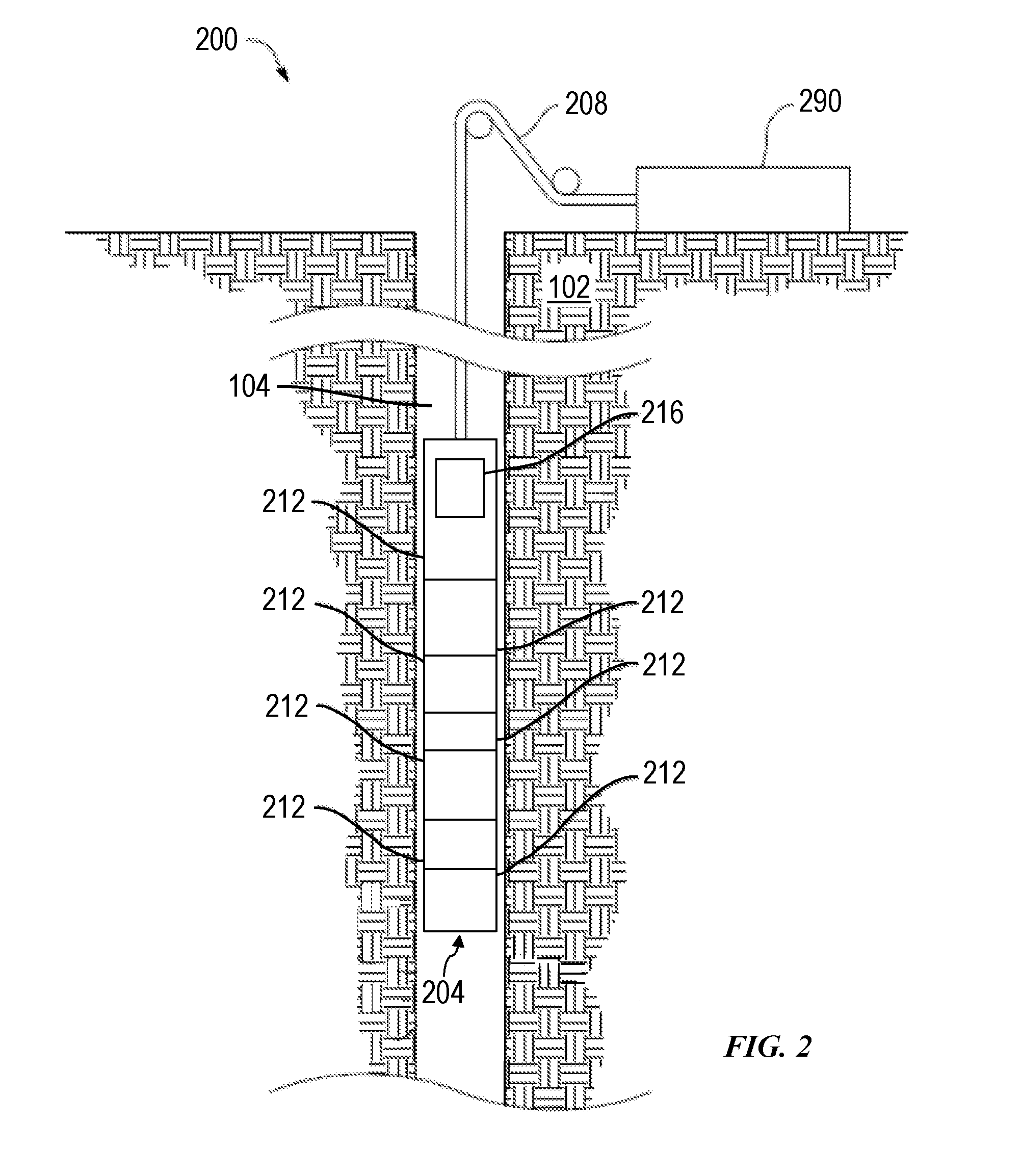
[0028] FIG. 2 is a schematic view of another example wellsite system 200 to which one or more aspects of the present disclosure may be applicable. The wellsite system 200 may be onshore or offshore. In the example wellsite system 200 shown in FIG. 2, a tool string 204 is conveyed into the wellbore 104 via a conveyance means 208, which may be or comprise a wireline, a slickline, or a fluid conduit, such as coiled tubing, completion tubing, a liner, or a casing. As with the wellsite system 100 shown in FIG. 1, the example wellsite system 200 of FIG. 2 may be utilized for evaluation of the wellbore 104 and/or the formation 102 penetrated by the wellbore 104.
[0029] The tool string 204 is suspended in the wellbore 104 from the lower end of the conveyance means 208, which may be a multi-conductor logging cable spooled on a surface winch (not shown). The conveyance means 208 may include at least one conductor that facilitates data communication between the tool string 204 and surface equipment 290 disposed on the surface. The surface equipment 290 may have one or more aspects in common with the surface equipment 190 shown in FIG. 1.
[0030] The tool string 204 and conveyance means 208 may be structured and arranged with respect to a service vehicle (not shown) at the wellsite. For example, the conveyance means 208 may be connected to a drum (not shown) at the wellsite surface, such that rotation of the drum may raise and lower the tool string 204. The drum may be disposed on a service vehicle or a stationary platform. The service vehicle or stationary platform may further contain the surface equipment 290.
[0031] The tool string 204 comprises one or more elongated housings encasing or otherwise carrying various electronic components and modules schematically represented in FIG. 2. For example, the illustrated tool string 204 includes several modules 212, at least one of which may be or comprise at least a portion of a packer tool as described below. Other implementations of the downhole tool string 204 within the scope of the present disclosure may include additional or fewer components or modules relative to the example implementation depicted in FIG. 2.
[0032] The wellsite system 200 also includes a data processing system that can include one or more, or portions thereof, of the following: the surface equipment 290, control devices and electronics in one or more modules of the tool string 204 (such as a downhole controller 216), a remote computer system (not shown), communication equipment, and other equipment. The data processing system may include one or more computer systems or devices and/or may be a distributed computer system. For example, collected data or information may be stored, distributed, communicated to a human wellsite operator, and/or processed locally or remotely.
[0033] The data processing system may, whether individually or in combination with other system components, perform the methods and/or processes described below, or portions thereof. Methods and/or processes within the scope of the present disclosure may be implemented by one or more computer programs that run in a processor located, for example, in one or more modules 212 of the tool string 204 and/or the surface equipment 290. Such programs may utilize data received from the downhole controller 216 and/or other modules 212 via the conveyance means 208, and may transmit control signals to operative elements of the tool string 204. The programs may be stored on a tangible, non-transitory, computer-usable storage medium associated with the one or more processors of the downhole controller 216, other modules 212 of the tool string 204, and/or the surface equipment 290, or may be stored on an external, tangible, non-transitory, computer-usable storage medium that is electronically coupled to such processor(s). The storage medium may be one or more known or future-developed storage media, such as a magnetic disk, an optically readable disk, flash memory, or a readable device of another kind, including a remote storage device coupled over a communication link, among other examples.
[0034] Although FIGS. 1 and 2 illustrate example wellsite systems 100 and 200, respectively, which convey a downhole tool/string into the wellbore 104, other example implementations consistent with the scope of this disclosure may utilize other conveyance means to convey tools/strings into the wellbore 104. Additionally, other downhole tools within the scope of the present disclosure may comprise components in a non-modular construction also consistent with the scope of this disclosure.
[0035] FIG. 3 is a schematic view of at least a portion of an example implementation of an expandable packer tool 300 configured to be deployed or conveyed within a wellbore according to one or more aspects of the present disclosure. The packer tool 300 may be implemented as one or more of the LWD modules 144 or MWD modules 146 shown in FIG. 1, and/or one or more of the modules 212 shown in FIG. 2, and may thus be conveyed within the wellbore via a wireline, a slickline, a drill string, coiled tubing, completion tubing, a liner, a casing, and/or other conveyance means. As described below, the packer tool 300 is an assembly of a plurality of components operating together in a coordinated manner and, thus, may also be referred to as a packer assembly.
[0036] The expandable packer tool 300 comprises a first end assembly 310 at a first end of the packer tool 300, and a second end assembly 312 at an opposing second end of the packer tool 300. The end assemblies 310, 312 may be or comprise connector assemblies, such as may be configured to couple the packer tool 300 within a tool string. For example, the end assembly 310 may be coupled with a first (e.g., uphole) portion 302 of the tool string, and the end assembly 312 may be coupled with a second (e.g., downhole) portion 304 of the tool string. The tool string may be the BHA 140 shown in FIG. 1, the tool string 204 shown in FIG. 2, and/or other tool strings within the scope of the present disclosure.
[0037] A mandrel 314 (e.g., a tube) extends between the end assemblies 310, 312. The first and/or second end assembly 310, 312 may be connected (e.g., fixedly or slidably) with the mandrel 314, and at least a portion of the first and/or second end assembly 310, 312 may extend around the mandrel 314. An expandable (e.g., flexible, elastic) packer 316 is disposed around the mandrel 314, and may be sealingly connected with one or both of the end assemblies 310, 312. In a fully retracted state of the packer 316, an inner surface of the packer 316 may be disposed against and/or in contact with an outer profile (e.g., surface) of the mandrel 314. In an expanded state of the packer 316, the inner surface of the packer 316 may be disposed away from the outer profile of the mandrel 314, and an outer surface of the packer 316 may be disposed against a sidewall of the wellbore/casing to fluidly seal a portion of the wellbore/casing and/or to maintain the packer tool 300 in position within the wellbore/casing. The mandrel 314 comprises a fluid port 318 on an outer surface of the mandrel 314, and a flowline 320 extending within the mandrel 314 and in fluid communication with the port 318. The port 318 may be fluidly connected with an inner portion of the packer 316, such as may permit inflation and deflation of the packer 316.
[0038] The tool string may comprise a pump for expanding and retracting the packer 316. For example, the upper tool string portion 302 may comprise a fluid pump 306 fluidly connected with a flowline 308 extending within the upper tool string portion 302. Coupling the end assembly 310 with the upper tool string portion 302 may also fluidly connect the flowlines 308, 320, thereby fluidly connecting the pump 306 with the flowline 320 and the port 318. Accordingly, during downhole operations, the pump 306 may pump a fluid into the packer 316 via the flowlines 308, 320 and the port 318 to expand the packer 316 away from the mandrel 314 against the sidewall of the wellbore/casing. The pump 306 may also pump the fluid out of the packer 316 via the flowlines 308, 320 and the port 318 to retract the packer 316 away from the sidewall of the wellbore/casing toward and into contact with the mandrel 314. Although not shown, the packer tool 300 may comprise multiple instances of the port 318 distributed circumferentially around the mandrel 314 (i.e., around an outer surface of the mandrel 314), with each port being fluidly connected with an inner portion of the packer 316 and with the flowline 320, such as may permit inflation and deflation of the packer 316.
[0039] The packer 316 also includes drains 330 for focused sampling. Each focused sampling drain 330 includes a sample inlet or drain 332 and a guard inlet or drain 334, separated by an elongated, ring-shaped portion of rubber and/or other material forming the packer 316. The sample and guard drains 332, 334 conduct fluid from the formation into corresponding flowlines 336 embedded within the packer 316 or otherwise inside the packer 316. The focused sampling drains 330 (and perhaps at least a portion of one or more of the flowlines 336) may be imbedded within one or more outer layers 338 of the packer 316, and may thus move radially outward while the packer 316 is expanded, whether such expansion is via inflation of the packer 316 itself or via inflation of an internal bladder 340 located between the mandrel 314 and the packer 316.
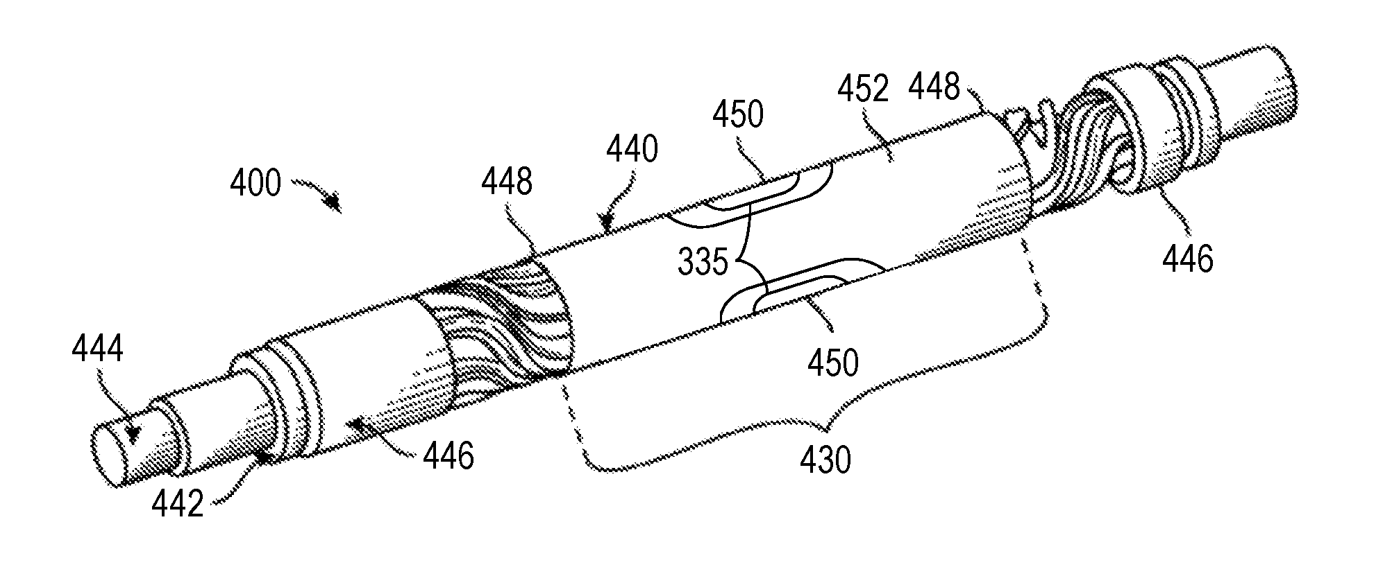
[0040] FIG. 4 is a perspective view of an example implementation of the packer tool 300 shown in FIG. 3, and designated in FIG. 4 by reference number 400. The packer tool 400 includes an outer layer 440 (e.g., an outer skin) that is expandable in the wellbore/casing to form a seal with the surrounding wellbore/casing wall. The packer tool 400 further includes an inner, inflatable bladder 442 disposed within an interior of the outer layer 440. The inner bladder 442 (e.g., inner packer) may be selectively expanded by fluid delivered via an inner mandrel 444, such as via the flowlines 308, 320 of the mandrel 314 described above. End portions of the packer tool 400 (such as the end portions 310, 312 described above) may include mechanical fittings 446 mounted around the inner mandrel 444 and engaged with axial ends 448 of outer layer 440.
[0041] The outer layer 440 includes one or more focused sampling drains 450 (such as the focused sampling drains 330 described above) through which formation fluid is collected when the outer layer 440 is expanded against the surrounding wellbore/casing wall. The focused sampling drains 450 may be embedded radially into the outer layer 440, such as into a cylindrical, elastomeric sealing portion 452 selected for hydrocarbon based applications (e.g., nitrile rubber (NBR), hydrogenated nitrile butadiene rubber (HNBR), fluorocarbon rubber (FKM), etc.).
[0042] One or more aspects pertain to the sealing portion 452 of the outer layer 440, such as to optimize sealing efficiency while permitting focused sampling (i.e., guard and sample) on a continuous ring. Conventionally, the outer rubber layer has been made of a thick rubber cylinder, with embedded flowlines and drains bonded to rubber. However, such arrangements can lead to excessive elongation of the rubber, which can increase the level of stress on bonding interfaces between the drains and the surrounding rubber, and potentially increasing the risk of failure due to bonding issues. The present disclosure introduces a packer with optimized flow and operational performance.
[0043] As described above, the packer is carried on the sampling/packer tool 300, 400 having one or more hydraulic pumps. Well fluid is pumped to inflate the packer so that the sealing portion 452 contacts and seals a portion of the wellbore/casing. Fluid is then drawn from the subterranean formation within the sealed portion of the wellbore/casing by operating the same pump (via valving) or another pump to create a pressure drop (drawdown) that urges reservoir fluid from the formation. The drawdown pump is connected to the focused sampling drains 450 so that the drawdown pressure is transmitted to the formation through the focused sampling drains 450.
[0044] Because the packer is inflatable or otherwise expandable, dimensions of the drains are optimized via a compromise between fluid efficiency (bigger drains provide better sampling efficiency) and elongation capabilities (smaller drains have less impact on the ability of the packer to inflate). The present disclosure thus pertains to enhancing the shape of the outer rubber layer in order to maximize packer sampling and geometrical symmetry while ensuring adequate (if not best) sealing efficiency and lowering peeling forces acting on the rubber bonding interfaces.
[0045] As described above, the outer rubber layer is composed of a sealing element made of NBR, HNBR, FKM, and/or other elastomeric materials. The sample and guard zones or drains 332, 334 and at least a portion of one or more of the flowlines 336 are embedded within the sealing portion 452 in a manner permitting focused sampling. The center, sample drain 332 of each focused sampling drain 330, 450 collects reservoir fluid, while the external, guard drain 334 of each focused sampling drain 330, 450 protects the sample drain 332 from mud invasion. Both sample and guard drains 332, 334 of each focused sampling drain 330, 450 are sealed by an elastomeric portion 335 having a shape that protects against extrusion. Each focused sampling drain 330, 450 can be made in a manner permitting the sample drain 332 part to move freely relative to the guard drain 334, such as may permit better conformance to the surface of the wellbore/casing.
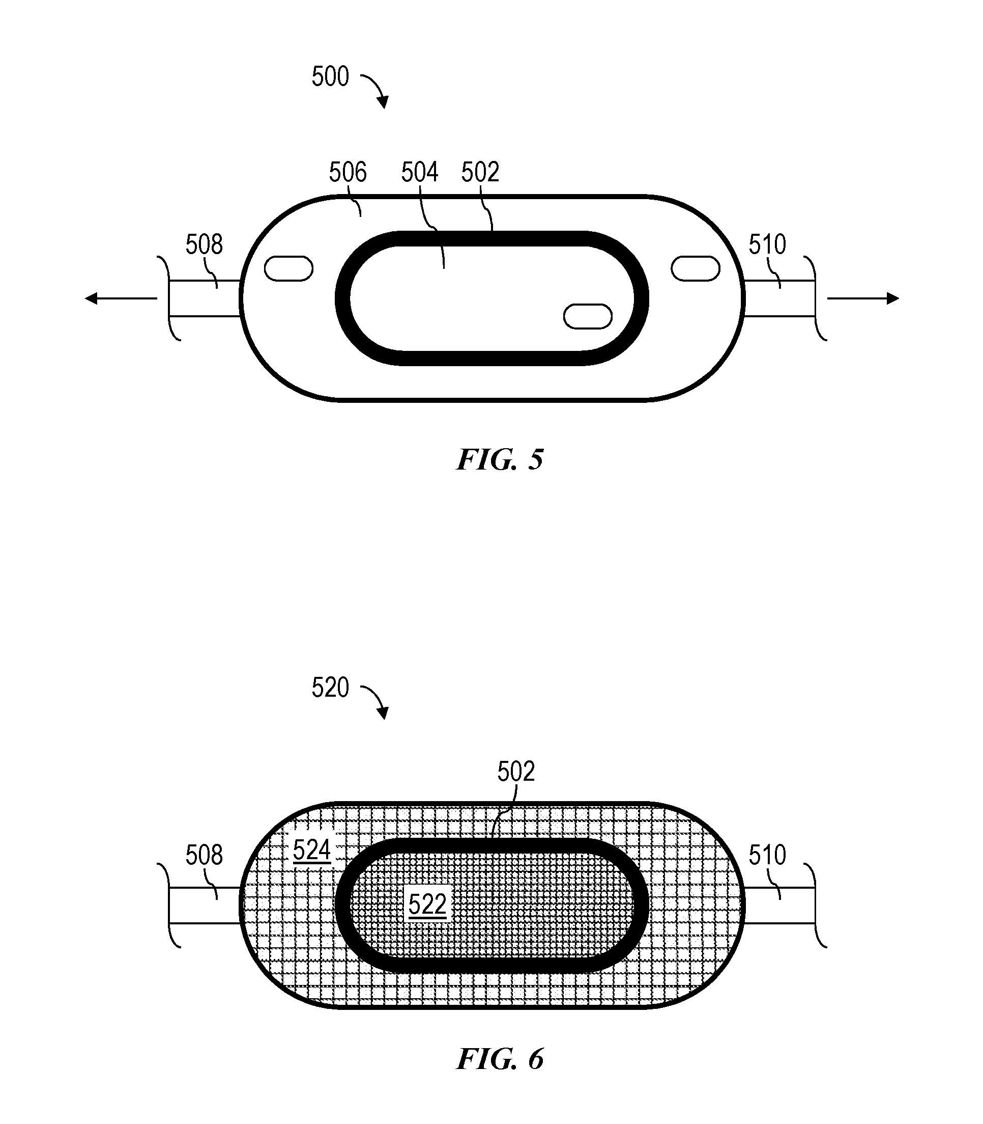
[0046] FIG. 5 is a schematic view of an example implementation of the focused sampling drains 330, 450 described above, and designated in FIG. 5 by reference number 500. The focused sampling drain 500 includes a rubber portion 502 that seals against the surrounding wellbore/casing to fluidly isolate the sample inlet or drain 504 within the guard inlet or drain 506. FIG. 5 also depicts flowlines extending from the focused sampling drain 500, such as a guard flowline 508 extending from the guard inlet 506 and a sample flowline 510 extending from the sample inlet 504. The flowlines 508, 510 may be substantially similar to (or the same as) the flowlines described above.
[0047] FIG. 6 is a schematic view of another example implementation of the focused sampling drain 500 shown in FIG. 5, and designated in FIG. 6 by reference number 520. The focused sampling drain 520 depicted in FIG. 6 is substantially similar to (or the same as) the focused sampling drain 500 depicted in FIG. 5, except that the focused sampling drain 520 includes a screen (e.g., a filter) 522 set in (or at the surface of) the sample inlet 504 and another screen 524 set in (or at the surface of) the guard inlet 506. Implementations within the scope of the present disclosure may include one, both, or neither of the screens 522, 524. The screens 522, 524 may aid in protecting the flowlines 508, 510 from mud invasion and subsequent plugging. In implementations including both screens 522, 524, the screens 522, 524 may have the same or different mesh/grid sizes. For example, the guard inlet 506 may be more prone to plugging, so the guard screen 524 may have a larger mesh/grid size than the sample screen 522. Other means for filtering the sample/guard inlets 504/506 are also within the scope of the present disclosure.
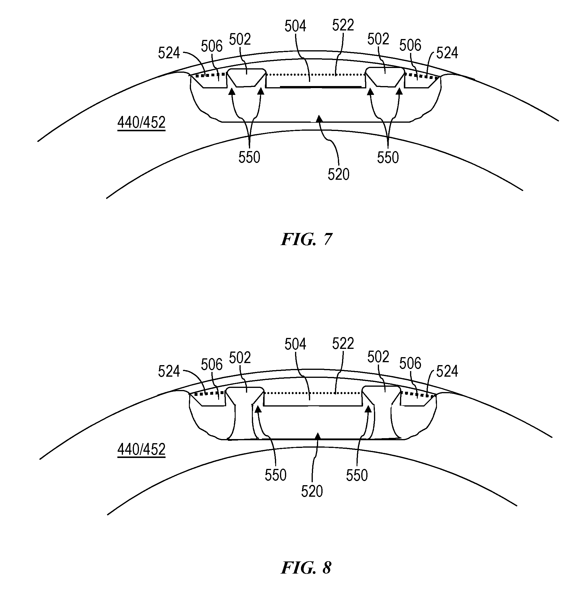
[0048] The intermediate rubber portion 502 in FIGS. 5 and 6 may be protected against extrusion by the structure of the focused sampling drain 500, 520, such as to be able to establish the pressure differential utilized during focused sampling operations, perhaps including a pressure differential between the sample inlet 504 and the guard inlet 506. An example of such structure is depicted in FIGS. 7 and 8. FIG. 7 is a schematic end view of the focused sampling drain 520, and FIG. 8 is a schematic sectional view of the focused sampling drain 520. Both views show the outer rubber layer 440/452, the rubber portion 502 separating the sampling zone 504 and the guard zone 506, the sampling screen 522, and the guard screen 524. Both views also show anti-extrusion shoulders or other structures 550 shaped to protect the rubber portion 502. The structures 550 may be or comprise a portion of the outer layer 440, 452 protruding outwardly and abutting the rubber portion 502 on one or opposing sides to support the rubber portion 502 in position. Thus, one of the structures 550 may surround the rubber portion 502 on the guard zone 506 side (i.e., outer side) of the rubber portion 502 and the other structure 550 may be located on the sampling zone 504 side (i.e., inner side) of the rubber portion 502 and, thus, be surrounded by the rubber portion 502. FIG. 8 also depicts how the guard zone 506 may be separated from the sample zone 504 by part of the rubber forming the outer layer 440/452.
[0049] However, the rubber portion 502 may not be sufficiently protected against extrusion, because the focused sampling drain 520 may not be sufficiently compliant to adequately conform to the uneven surface of the surrounding wellbore/casing. The present disclosure also introduces one or more aspects that may address this issue. For example, the rubber portion 502 may be removable, so that it can be replaced between jobs and thus increase product lifetime.
[0050] Alternatively (or additionally), the rubber portion separating the guard and sample inlets may be configured as a compliant, anti-extrusion system, such as by utilizing compliant, extrusion-resistant materials. The anti-extrusion system may be made in a material that may aid in ensuring compliance to the wellbore/casing, including free displacement in the direction perpendicular to the external surface of the drain, and extrusion resistance in the form of mechanical resistance in the direction parallel to the surface of the drain. An example of such material is carbon fibers embedded in rubber.
[0051] Another example is to embed segmented metallic reinforcements. FIGS. 9 and 10 depict such an example implementation of the rubber portion 502, designated in FIGS. 9 and 10 by reference number 600. FIG. 9 is an external view of the sealing pad assembly 600 (looking from the reservoir to the sealing pad assembly 600), and FIG. 10 is a sectional view as indicated in FIG. 9.
[0052] The metallic reinforcement may be made of vertical metallic parts 602, set side-by-side and free to move vertically. A rubber sealing layer 604 surrounds the sliding metal parts 602. An optional rubber layer 606 may interpose the sliding metal parts 602 and the sealing layer 604. An optional outer rubber layer 608 may surround the sealing layer 604. As depicted in FIG. 10, the outer surfaces of the layers 604, 606, 608 may protrude above the outer surface 603 of the sliding metal parts 602.
[0053] A gap between the sliding metal parts 602 may exist when the packer is set against the wellbore/casing. The optional layer 606 may aid in reducing (or eliminating) resulting extrusion of the sealing layer 604. The layer 606 may be reinforced, such as via embedded carbon fibers, other fibers, and/or other reinforcing materials. The outer layer 608 may similarly be reinforced. Thus, the layers 606, 608 may be or comprise sealing layers and/or support layers configured to prop or otherwise support the sealing layer 604, thereby protecting the sealing layer 604 against extrusion.
[0054] The metallic sliding parts 602 may each be a vertically-extending metallic member, although other shapes may also be utilized to also provide compliance to the wellbore/casing and still provide anti-extrusion means. The sliding parts 602 may be manufactured via machining, 3D printing, and/or other means.
[0055] FIG. 11 is a side sectional view of a portion of a focused sampling (or sealing) drain 700 that may be implemented as part of a packer tool assembly according to one or more aspects of the present disclosure. The focused sampling drain 700 may comprise one or more features and/or modes of operation of the focused sampling drains 330, 450, 500, 520 described above and shown in one or more of FIGS. 3-8.
[0056] The focused sampling drain 700 may comprise a sealing member 702 (e.g., a sealing pad or portion) having a predetermined shape such that it can be inserted in the focused sampling drain 700, provide sealing when the focused sampling drain 700 is against a formation, and can be removed after a job and replaced by another sealing member for a future job. The sealing member 702 may comprise an elongated, generally ring-shaped geometry extending around a sample inlet or drain 704 of the focused sampling drain 700 and configured to seal against the sidewall of a surrounding wellbore/casing, such as to fluidly isolate the sample drain 704 from a guard inlet or drain 706 of the focused sampling drain 700.
[0057] The sealing member 702 may be at least partially embedded within a drain 712 (e.g., outer rubber layer, outer skin) of the focused sampling drain 700 and/or the packer assembly. The sealing member 702 may be disposed at least partially within a chamber or cavity 715 shaped or otherwise configured to accommodate the sealing member 702 and, thus, support, retain, and/or maintain the sealing member 702 in connection with the drain 712. The cross-sectional shape or profile of the cavity 715 may follow, outline, and/or trace the cross-sectional shape or profile (e.g., outer surface 718) of at least a portion of the sealing member 702.
[0058] One or more portions of the drain 712 may protrude outwardly above the surface of the drain 712 in the form of one or more shoulders 714, 716 abutting the sealing member 702 on one or opposing sides to further support the sealing member 702 in position. One shoulder 716 may surround the sealing member 702 on the guard drain 706 side (i.e., outer side) of the sealing member 702 and the other shoulder 714 may be located on the sample drain 704 side (i.e., inner side) of the sealing member 702 and, thus, be surrounded by the sealing member 702. The shoulders 714, 716 may form or define at least a portion of the cavity 715 accommodating the sealing member 702. One or more of the shoulders 714, 716 may prevent, inhibit, or reduce extrusion (e.g., movement and/or deformation) of the sealing member 702 in a direction parallel to the sample and guard drains 704, 706 (or the drain 712), as indicated by arrows 720, such as when a pressure differential is being established between the sample and guard drains 704, 706, thereby permitting the intended pressure differential to be established, such as during focused sampling operations. For example, during drawdown, the shoulders 714, 716 may prevent, inhibit, or reduce extrusion of the sealing member 702 in a direction toward the sample drain 704.
[0059] The sealing member 702 may comprise a sealing portion 708 configured to contact and seal against the sidewall of the surrounding wellbore/casing and an anchor portion 710 configured to connect or otherwise maintain the sealing member 702 in an intended position with respect to the drain 712. The sealing portion 708 may protrude out of the cavity 715 above an outer surface of the drain 712 and the anchor portion 710 may be embedded or otherwise disposed within the cavity 715 beneath the outer surface of the drain 712. The shoulders 714, 716 of the drain 712 may be referred to as external shoulders 714, 716 supporting the external sealing portion 708 of the sealing member 702. The drain 712 defining the cavity 715 may also or instead comprise one or more internal protrusions or shoulders 724 configured to support the internal anchor portion 710 of the sealing member 702 in an intended position. For example, the anchor portion 710 may comprise one or more protrusions or shoulders 722 configured to latch against or otherwise abut the one or more of the internal shoulders 724. The shoulders 722 may extend outwardly away from each other and the shoulders 724 may extend inwardly toward each other and/or with respect to the cavity 715. Accordingly, the anchor portion 710 may anchor, latch, or otherwise mechanically connect the sealing member 702 to the drain 712. The anchor portion 710 may, thus, prevent, inhibit, or reduce movement and/or extrusion of the sealing member 702 in the direction parallel to the sample and guard drains 704, 706, as indicated by arrows 720, such as when a pressure differential is being established between the sample and guard drains 704, 706.
[0060] Material forming the sealing member 702 may be or comprise an elastomeric material, such as NBR, HNBR, and/or FKM, among other examples. The material forming the sealing member 702 may also or instead be or comprise a mixture or combination of an elastomeric and thermoplastic material. The material forming the sealing member 702 may also or instead be reinforced, such as via embedded carbon fibers, other fibers, and/or other reinforcing materials. For example, the material forming the anchor portion 710 may comprise or be reinforced with thermoplastic material, carbon fibers, other fibers, a metal, and/or other reinforcing materials, such as to increase mechanical strength or stiffness of the anchor portion 710.
[0061] The sealing member 702 may be manually inserted into the cavity 715, such as by pressing or pushing the sealing member 702 into the cavity 715 by hand or with a tool such that the shoulders 722 of the anchor portion 710 are located below or otherwise latched against the shoulders 724 of the drain 712. The sealing member 702 may be manually pulled out of or otherwise removed from the cavity 715 after a job by hand or with a tool.
[0062] FIG. 12 is a side sectional view of a portion of a focused sampling (or sealing) drain 750 that may be implemented as part of a packer tool assembly according to one or more aspects of the present disclosure. The focused sampling drain 750 may comprise one or more features and/or modes of operation of the focused sampling drains 330, 450, 500, 520, 700 described above and shown in one or more of FIGS. 3-8 and 11, including where indicated by same numerals.
[0063] The focused sampling drain 750 may comprise a sealing member 752 (e.g., a sealing pad or portion) having a predetermined shape such that it can be inserted in the focused sampling drain 750, provide sealing when the focused sampling drain 750 is against a formation, and can be removed after a job and replaced by another sealing member for a future job. The sealing member 752 may comprise an elongated ring-shaped or otherwise rounded (e.g., elliptical, superelliptical, oval, etc.) geometry extending around a sample inlet or drain 704 of the focused sampling drain 750 and configured to seal against the sidewall of a surrounding wellbore/casing, such as to fluidly isolate the sample drain 704 from a guard inlet or drain 706 of the focused sampling drain 750. However, the sealing member 752 may instead comprise generally circular geometry.
[0064] The focused sampling drain 750 may comprise one or more backup or support members 754, 756, each contacting or other otherwise abutting the sealing portion 708 of the sealing member 752 on a corresponding side of the sealing member 752. The support members 754, 756 may comprise an elongated ring-shaped or otherwise rounded geometry following or tracing the sealing member 752. Thus, the support member 756 may surround the sealing member 752 on the guard drain 706 side (i.e., outer side) of the sealing member 752 and/or the support member 754 may be located on the sample drain 704 side (i.e., inner side) of the sealing member 752 and, thus, be surrounded by the sealing member 752. Each support member 754, 756 may be located between and abutting the sealing portion 708 and a corresponding shoulder 714, 716 of the drain 712. Each support member 754, 756 may be disposed within a corresponding chamber, channel, or cavity surrounded on each side by the sealing member 752 and the drain 712, thereby latching or otherwise maintaining each support member 754, 756 in position against the sealing member 752. For example, the sealing portion 708 may surround each support member 754, 756 on two sides (e.g., upper and inner sides) and the drain 712, including the shoulders 716, may surround each support member 754, 756 on two sides (e.g., lower and outer sides).
[0065] Material forming the support members 754, 756 may be or comprise a material having a greater stiffness than the material forming the sealing member 752. The material forming the support members 754, 756 may be or comprise, for example, a thermoplastic material or a mixture or combination of an elastomeric and thermoplastic material. The material forming the support members 754, 756 may also or instead be reinforced, such as via embedded technical fibers, carbon fibers, other fibers, and/or other reinforcing materials. The material forming the support members 754, 756 may also or instead be or comprise a metal. Accordingly, each support members 754, 756 may further prevent, inhibit, or reduce extrusion (e.g., movement and/or deformation) of the sealing member 752 in the direction parallel to the sample and guard drains 704, 706, as indicated by arrows 720, such as when a pressure differential is being established between the sample and guard drains 704, 706. For example, during drawdown, one or both backup members 754, 756 may prevent, inhibit, or reduce extrusion of the sealing member 752 in a direction toward the sample drain 704.
[0066] In view of the entirety of the present disclosure, including the figures and the claims, a person having ordinary skill in the art will readily recognize that the present disclosure introduces an apparatus comprising an expandable packer assembly for coupling within a tool string deployable within a wellbore, wherein the expandable packer assembly comprises: a guard inlet; a sample inlet surrounded by the guard inlet; and a sealing member surrounding the sample inlet and fluidly isolating the sample inlet from the guard inlet when the sealing member contacts a sidewall of the wellbore.
[0067] The expandable packer assembly may comprise a packer having an outer layer, and the sealing member may be detachably connected with the outer layer.
[0068] The expandable packer assembly may comprise a packer having an outer layer, and the sealing member may be manually connectable with and disconnectable from the outer layer.
[0069] The expandable packer assembly may comprise a packer having an outer layer, the outer layer may comprise a cavity in which the sealing member is received, and the sealing member may comprise a shoulder latching against a corresponding shoulder of the outer layer to connect the sealing member to the outer layer.
[0070] The expandable packer assembly may comprise a support member abutting the sealing member and inhibiting extrusion of the sealing member when a pressure differential exists between the sample and guard inlets. The sealing member may surround the support member. The support member may comprise a material that is stiffer than material forming the sealing member. The support member may comprise a plurality of sliding metal members.
[0071] The expandable packer assembly may comprise a packer having an outer layer, and a shoulder may protrude from the outer layer, abut the sealing member, and/or inhibit extrusion of the sealing member when a pressure differential exists between the sample and guard inlets.
[0072] The present disclosure also introduces an apparatus comprising an expandable packer assembly for coupling within a tool string deployable within a wellbore, wherein the expandable packer assembly comprises: an expandable packer having an outer layer; a sample drain at least partially located on the outer layer and operable to receive formation fluid; a guard drain at least partially located on the outer layer and surrounding the sample drain; and a sealing member at least partially located on the outer layer and surrounding the sample drain, wherein the sealing member fluidly isolates the sample drain from the guard drain when the sealing member contacts a sidewall of the wellbore, and wherein the sealing member is detachably connected with the outer layer.
[0073] The sealing member may be manually connectable and disconnectable with the outer layer.
[0074] The outer layer may comprise a cavity in which the sealing member is received, and the sealing member may comprise a shoulder latching against a corresponding shoulder of the outer layer to connect the sealing member to the outer layer.
[0075] The expandable packer assembly may comprise a support ring abutting the sealing member. The sealing member may surround the support ring. The support ring may comprise a material that is stiffer than material forming the sealing member. The support ring may comprise a plurality of sliding metal members.
[0076] The outer layer may comprise a protruding shoulder abutting the sealing member.
[0077] The present disclosure also introduces an apparatus comprising an expandable packer assembly for coupling within a tool string deployable within a wellbore, wherein the expandable packer assembly comprises: an expandable packer having an outer layer; a sample drain at least partially located on the outer layer and operable to receive formation fluid; a guard drain at least partially located on the outer layer and surrounding the sample drain; and a sealing member at least partially located on the outer layer and surrounding the sample drain, wherein the sealing member fluidly isolates the sample drain from the guard drain when the sealing member contacts a sidewall of the wellbore, and wherein the outer layer comprises an external shoulder abutting the sealing member.
[0078] The sealing member may be detachably connected with the outer layer.
[0079] The sealing member may be manually connectable and disconnectable with the outer layer.
[0080] A drain may comprise the sample drain, the guard drain, and a cavity in which the sealing member is received, and the sealing member may comprise a shoulder latching against a corresponding internal shoulder of the drain to connect the sealing member to the drain.
[0081] The expandable packer assembly may comprise a support ring abutting the sealing member. The sealing member may surround the support ring. The support ring may comprise a material that is stiffer than material forming the sealing member. The support ring may comprise a plurality of sliding metal members.
[0082] The external shoulder may protrude outwardly from an outer surface of the outer layer.
[0083] The external shoulder may be a first external shoulder abutting the sealing member on a first side, and the outer layer may comprise a second external shoulder abutting the sealing member on a second side opposite the first side.
[0084] The foregoing outlines features of several embodiments so that a person having ordinary skill in the art may better understand the aspects of the present disclosure. A person having ordinary skill in the art should appreciate that they may readily use the present disclosure as a basis for designing or modifying other processes and structures for carrying out the same functions and/or achieving the same benefits of the implementations introduced herein. A person having ordinary skill in the art should also realize that such equivalent constructions do not depart from the spirit and scope of the present disclosure, and that they may make various changes, substitutions and alterations herein without departing from the spirit and scope of the present disclosure.
[0085] The Abstract at the end of this disclosure is provided to permit the reader to quickly ascertain the nature of the technical disclosure. It is submitted with the understanding that it will not be used to interpret or limit the scope or meaning of the claims.
* * * * *
D00000
D00001
D00002
D00003
D00004
D00005
D00006
D00007
XML
uspto.report is an independent third-party trademark research tool that is not affiliated, endorsed, or sponsored by the United States Patent and Trademark Office (USPTO) or any other governmental organization. The information provided by uspto.report is based on publicly available data at the time of writing and is intended for informational purposes only.
While we strive to provide accurate and up-to-date information, we do not guarantee the accuracy, completeness, reliability, or suitability of the information displayed on this site. The use of this site is at your own risk. Any reliance you place on such information is therefore strictly at your own risk.
All official trademark data, including owner information, should be verified by visiting the official USPTO website at www.uspto.gov. This site is not intended to replace professional legal advice and should not be used as a substitute for consulting with a legal professional who is knowledgeable about trademark law.