Carrier With Handle Features
Smalley; Brian
U.S. patent application number 16/253803 was filed with the patent office on 2019-07-25 for carrier with handle features. The applicant listed for this patent is Graphic Packaging International, LLC. Invention is credited to Brian Smalley.
| Application Number | 20190225398 16/253803 |
| Document ID | / |
| Family ID | 67299736 |
| Filed Date | 2019-07-25 |


| United States Patent Application | 20190225398 |
| Kind Code | A1 |
| Smalley; Brian | July 25, 2019 |
Carrier With Handle Features
Abstract
A carrier for holding at least one article includes a plurality of panels and a handle. The plurality of panels extends at least partially around an interior of the carrier, and the plurality of panels includes a top panel, a bottom panel, and at least one side panel. The handle includes at least one handle feature in the top panel. The at least one handle feature includes a plurality of foldably connected handle sections that includes a first outer section and a second outer section each foldably connected to a central section and such that the at least one handle feature is positionable between a first, substantially flat configuration and a second, substantially recessed configuration wherein the handle is activated for carrying the carrier.
| Inventors: | Smalley; Brian; (Bristol, GB) | ||||||||||
| Applicant: |
|
||||||||||
|---|---|---|---|---|---|---|---|---|---|---|---|
| Family ID: | 67299736 | ||||||||||
| Appl. No.: | 16/253803 | ||||||||||
| Filed: | January 22, 2019 |
Related U.S. Patent Documents
| Application Number | Filing Date | Patent Number | ||
|---|---|---|---|---|
| 62620537 | Jan 23, 2018 | |||
| Current U.S. Class: | 1/1 |
| Current CPC Class: | B65D 2571/00456 20130101; B65D 2571/00845 20130101; B65D 2571/00444 20130101; B65D 2571/00277 20130101; B65D 2571/0066 20130101; B65D 71/22 20130101; B65D 2571/0029 20130101; B65D 2571/00475 20130101; B65D 71/32 20130101; B65D 2571/00716 20130101; B65D 2571/00141 20130101; B65D 2571/00728 20130101; B65D 2571/00296 20130101; B65D 71/20 20130101; B65D 71/30 20130101 |
| International Class: | B65D 71/32 20060101 B65D071/32; B65D 71/20 20060101 B65D071/20; B65D 71/22 20060101 B65D071/22 |
Claims
1. A carrier for holding at least one article, the carrier comprising: a plurality of panels that extends at least partially around an interior of the carrier, the plurality of panels comprising a top panel, a bottom panel, and at least one side panel; and a handle comprising at least one handle feature in the top panel, the at least one handle feature comprises a plurality of foldably connected handle sections that comprises a first outer section and a second outer section each foldably connected to a central section and such that the at least one handle feature is positionable between a first, substantially flat configuration and a second, substantially recessed configuration wherein the handle is activated for carrying the carrier.
2. The carrier of claim 1, wherein each of the first outer section, the second outer section, and the central section are foldably connected to a body portion of the top panel at a curved fold line.
3. The carrier of claim 2, wherein the curved fold line is convex relative to a longitudinal centerline of the top panel.
4. The carrier of claim 3, wherein the curved fold line has endpoints at a free edge of the top panel.
5. The carrier of claim 1, wherein, in the second configuration of the handle, the central section extends downwardly from the body portion into the interior of the carrier.
6. The carrier of claim 5, wherein, in the second configuration of the handle, the first outer section and the second outer section extend downwardly from the body portion to form the substantially recessed configuration.
7. The carrier of claim 6, wherein, in the second configuration of the handle, the body portion of the top panel has an arched configuration.
8. The carrier of claim 1, wherein the first outer section is foldably connected to the central section at a first curved fold line and the second outer section is foldably connected to the central section at a second curved fold line.
9. The carrier of claim 8, wherein each of the first curved fold line and the second curved fold line is convex relative to a lateral centerline of the top panel.
10. The carrier of claim 1, wherein the at least one handle feature comprises a first tab foldably connected to the first outer section and a second tab foldably connected to the second outer section.
11. The carrier of claim 10, wherein the first tab and the second tab are separated from respective marginal portions of the first outer section and the second outer section at a respective curved cut.
12. The carrier of claim 11, wherein the respective curved cut at least partially defines a respective locking edge of the respective marginal portions.
13. The carrier of claim 1, wherein the at least one handle feature is a first handle feature and the central section is a first central section, and the handle comprises a second handle feature in the top panel, the second handle feature comprising a third outer section and a fourth outer section foldably connected to a second central section.
14. The carrier of claim 1, wherein the at least one side panel comprises a first upper side panel and a second upper side panel each foldably connected to the top panel.
15. The carrier of claim 14, wherein the at least one side panel further comprises a first lower side panel foldably connected to the first upper side panel and a second lower side panel foldably connected to the second upper side panel.
16. A blank for forming a carrier for holding at least one article, the blank comprising: a plurality of panels comprising a top panel, a bottom panel, and at least one side panel; and at least one handle feature in the top panel for forming a handle of the carrier formed from the blank, the at least one handle feature comprises a plurality of foldably connected handle sections that comprises a first outer section and a second outer section each foldably connected to a central section and such that the at least one handle feature is positionable between a first, substantially flat configuration and a second, substantially recessed configuration wherein the handle is activated for carrying the carrier formed from the blank.
17. The blank of claim 16, wherein each of the first outer section, the second outer section, and the central section are foldably connected to a body portion of the top panel at a curved fold line.
18. The blank of claim 17, wherein the curved fold line is convex relative to a longitudinal centerline of the top panel.
19. The blank of claim 18, wherein the curved fold line has endpoints at a free edge of the top panel.
20. The blank of claim 16, wherein the first outer section is foldably connected to the central section at a first curved fold line and the second outer section is foldably connected to the central section at a second curved fold line.
21. The blank of claim 20, wherein each of the first curved fold line and the second curved fold line is convex relative to a lateral centerline of the top panel.
22. The blank of claim 16, wherein the at least one handle feature comprises a first tab foldably connected to the first outer section and a second tab foldably connected to the second outer section.
23. The blank of claim 22, wherein the first tab and the second tab are separated from respective marginal portions of the first outer section and the second outer section at a respective curved cut.
24. The blank of claim 23, wherein the respective curved cut at least partially defines a respective locking edge of the respective marginal portions.
25. The blank of claim 16, wherein the at least one handle feature is a first handle feature and the central section is a first central section, and the handle comprises a second handle feature in the top panel, the second handle feature comprising a third outer section and a fourth outer section foldably connected to a second central section.
26. The blank of claim 16, wherein the at least one side panel comprises a first upper side panel and a second upper side panel each foldably connected to the top panel.
27. The blank of claim 26, wherein the at least one side panel further comprises a first lower side panel foldably connected to the first upper side panel and a second lower side panel foldably connected to the second upper side panel.
28. A method of forming a carrier for holding at least one article, the method comprising: obtaining a blank, the blank comprises a plurality of panels comprising a top panel, a bottom panel, and at least one side panel, the blank comprises at least one handle feature in the top panel for forming a handle, the at least one handle feature comprises a plurality of foldably connected handle sections that comprises a first outer section and second outer section each foldably connected to a central section; and folding the plurality of panels at least partially around an interior of the carrier and such that the at least one handle feature is positionable between a first, substantially flat configuration and a second, substantially recessed configuration wherein the handle is activated for carrying the carrier.
29. The method of claim 28, wherein each of the first outer section, the second outer section, and the central section are foldably connected to a body portion of the top panel at a curved fold line.
30. The method of claim 29, wherein the curved fold line is convex relative to a longitudinal centerline of the top panel.
31. The method of claim 30, wherein the curved fold line has endpoints at a free edge of the top panel.
32. The method of claim 28, wherein, in the second configuration of the handle, the central section extends downwardly from the body portion into the interior of the carrier.
33. The method of claim 32, wherein, in the second configuration of the handle, the first outer section and the second outer section extend downwardly from the body portion to form the substantially recessed configuration.
34. The method of claim 33, wherein, in the second configuration of the handle, the body portion of the top panel has an arched configuration.
35. The method of claim 28, wherein the first outer section is foldably connected to the central section at a first curved fold line and the second outer section is foldably connected to the central section at a second curved fold line.
36. The method of claim 35, wherein each of the first curved fold line and the second curved fold line is convex relative to a lateral centerline of the top panel.
37. The method of claim 28, wherein the at least one handle feature comprises a first tab foldably connected to the first outer section and a second tab foldably connected to the second outer section.
38. The method of claim 37, wherein the first tab and the second tab are separated from respective marginal portions of the first outer section and the second outer section at a respective curved cut.
39. The method of claim 38, wherein the respective curved cut at least partially defines a respective locking edge of the respective marginal portions.
40. The method of claim 28, wherein the at least one handle feature is a first handle feature and the central section is a first central section, and the handle comprises a second handle feature in the top panel, the second handle feature comprising a third outer section and a fourth outer section foldably connected to a second central section.
41. The method of claim 28, wherein the at least one side panel comprises a first upper side panel and a second upper side panel each foldably connected to the top panel.
42. The method of claim 41, wherein the at least one side panel further comprises a first lower side panel foldably connected to the first upper side panel and a second lower side panel foldably connected to the second upper side panel.
Description
CROSS-REFERENCE TO RELATED APPLICATION
[0001] This application claims the benefit of U.S. Provisional Patent Application No. 62/620,537, which was filed on Jan. 23, 2018.
INCORPORATION BY REFERENCE
[0002] The disclosure of U.S. Provisional Patent Application No. 62/620,537, which was filed on Jan. 23, 2018, is hereby incorporated by reference for all purposes as if presented herein in its entirety.
BACKGROUND OF THE DISCLOSURE
[0003] The present disclosure relates to cartons or carriers, blanks for forming cartons or carriers, and methods associated with cartons or carriers and associated blanks for holding and carrying at least one article. In one embodiment, the present disclosure relates to a carrier having handle features to facilitate carrying of the carrier.
SUMMARY OF THE DISCLOSURE
[0004] According to one aspect of the disclosure, a carrier for holding at least one article comprises a plurality of panels that extends at least partially around an interior of the carrier, the plurality of panels comprising a top panel, a bottom panel, and at least one side panel. The carrier further comprises a handle that comprises at least one handle feature in the top panel, the at least one handle feature comprises a plurality of foldably connected handle sections that comprises a first outer section and a second outer section each foldably connected to a central section. The at least one handle feature is positionable between a first, substantially flat configuration and a second, substantially recessed configuration wherein the handle is activated for carrying the carrier.
[0005] According to another aspect of the disclosure, a blank for forming a carrier for holding at least one article comprises a plurality of panels comprising a top panel, a bottom panel, and at least one side panel. The blank further comprises at least one handle feature in the top panel for forming a handle of the carrier formed from the blank, and the at least one handle feature comprises a plurality of foldably connected handle sections that comprises a first outer section and a second outer section each foldably connected to a central section. The at least one handle feature is positionable between a first, substantially flat configuration and a second, substantially recessed configuration wherein the handle is activated for carrying the carrier formed from the According to another aspect of the disclosure, a method of forming a carrier for holding at least one article comprises obtaining a blank, the blank comprises a plurality of panels comprising a top panel, a bottom panel, and at least one side panel. The blank further comprises at least one handle feature in the top panel for forming a handle, the at least one handle feature comprises a plurality of foldably connected handle sections that comprises a first outer section and second outer section each foldably connected to a central section. The method further comprises folding the plurality of panels at least partially around an interior of the carrier and such that the at least one handle feature is positionable between a first, substantially flat configuration and a second, substantially recessed configuration wherein the handle is activated for carrying the carrier.
[0006] According to common practice, the various features of the drawings discussed below are not necessarily drawn to scale. Dimensions of various features and elements in the drawings may be expanded or reduced to more clearly illustrate the embodiments of the disclosure.
BRIEF DESCRIPTION OF THE DRAWINGS
[0007] FIG. 1 is a plan view of an exterior surface of a blank for forming a carrier according to a first exemplary embodiment of the disclosure.
[0008] FIG. 2 is an enlarged view of the area identified in FIG. 1.
[0009] FIG. 3 is a first sequential perspective view of an assembly of a carrier formed from the blank of FIG. 1.
[0010] FIG. 4 is a second sequential perspective view of an assembly of a carrier formed from the blank of FIG. 1.
[0011] FIG. 5 is a perspective view of a carrier formed from the blank of FIG. 1 according to the first exemplary embodiment of the disclosure, and with at least one handle feature in a first configuration.
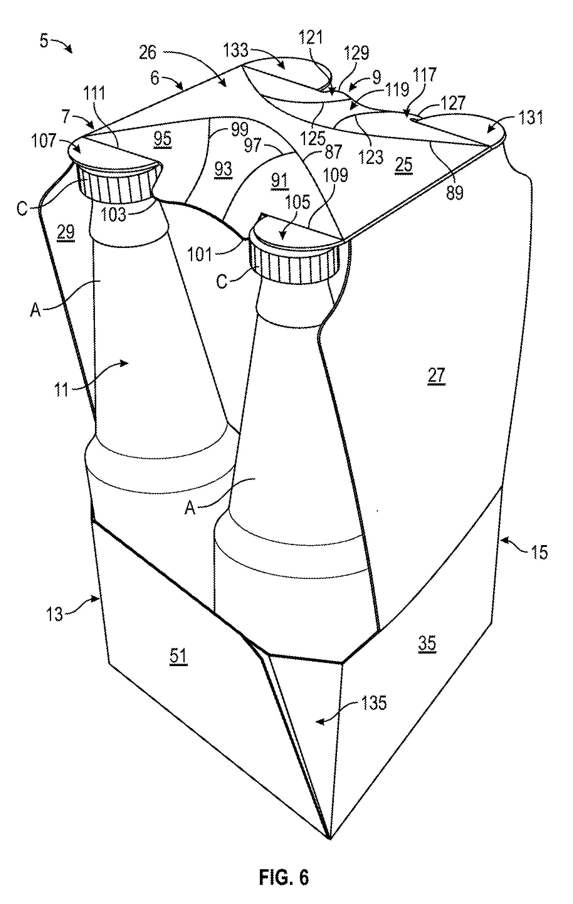
[0012] FIG. 6 is a perspective view of the carrier of FIG. 5 with the at least one handle feature in a second configuration.
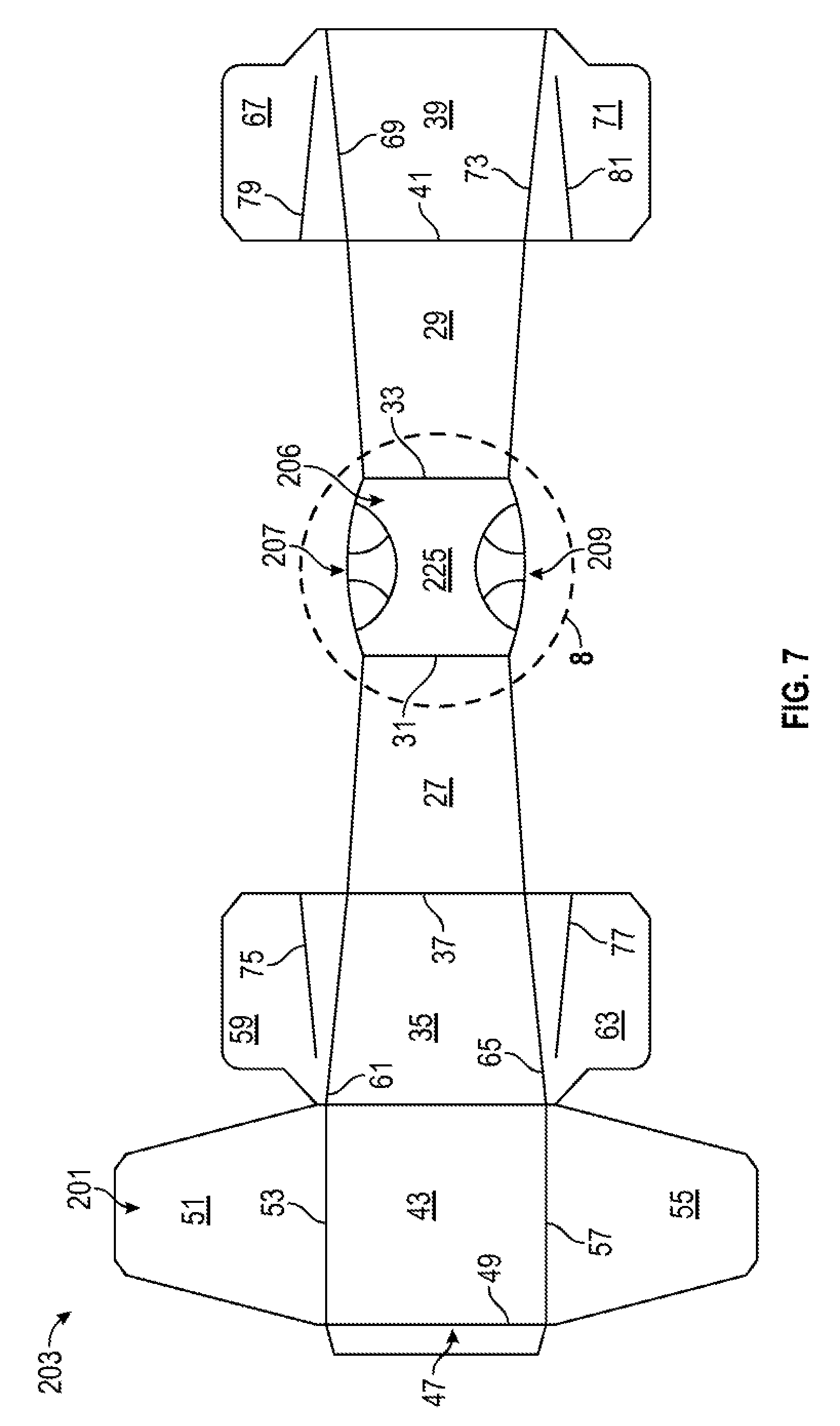
[0013] FIG. 7 is a plan view of an exterior surface of a blank for forming a carrier according to a second exemplary embodiment of the disclosure.
[0014] FIG. 8 is an enlarged view of the area identified in FIG. 7.
[0015] FIG. 9 is a perspective view of a carrier formed from the blank of FIG. 7 according to the second exemplary embodiment of the disclosure, and with at least one handle feature in a first configuration.
[0016] FIG. 10 is a perspective view of the carrier of FIG. 9 with the at least one handle feature in a second configuration.
[0017] Corresponding parts are designated by corresponding reference numbers throughout the drawings.
DETAILED DESCRIPTION OF THE EXEMPLARY EMBODIMENTS
[0018] Cartons or carriers according to the present disclosure can accommodate articles of numerous different shapes. For the purpose of illustration and not for the purpose of limiting the scope of the disclosure, the following detailed description describes articles such as containers, bottles, cans, etc., that at least partially disposed within the carton or carrier embodiments. The articles can be used for packaging food and beverage products, for example. The articles can be made from materials suitable in composition for packaging the particular food or beverage item, and the materials include, but are not limited to, glass; aluminum and/or other metals; plastics such as PET, LDPE, LLDPE, HDPE, PP, PS, PVC, EVOH, and Nylon; and the like, or any combination thereof.
[0019] Cartons or carriers according to the present disclosure can accommodate articles of any shape. For the purpose of illustration and not for the purpose of limiting the scope of the disclosure, the following detailed description describes beverage containers (e.g., aluminum beverage cans or glass bottles) as disposed within the carton or carrier embodiments. In this specification, the terms "lower," "bottom," "upper," and "top" indicate orientations determined in relation to fully erected and upright cartons or carriers. As described herein, cartons or carriers may be formed from blanks by overlapping multiple portions, panels, and/or end flaps. Such portions, panels, and/or end flaps may be designated herein in terms relative to one another, e.g., "first", "second", "third", etc., in sequential or non-sequential reference, without departing from the disclosure.
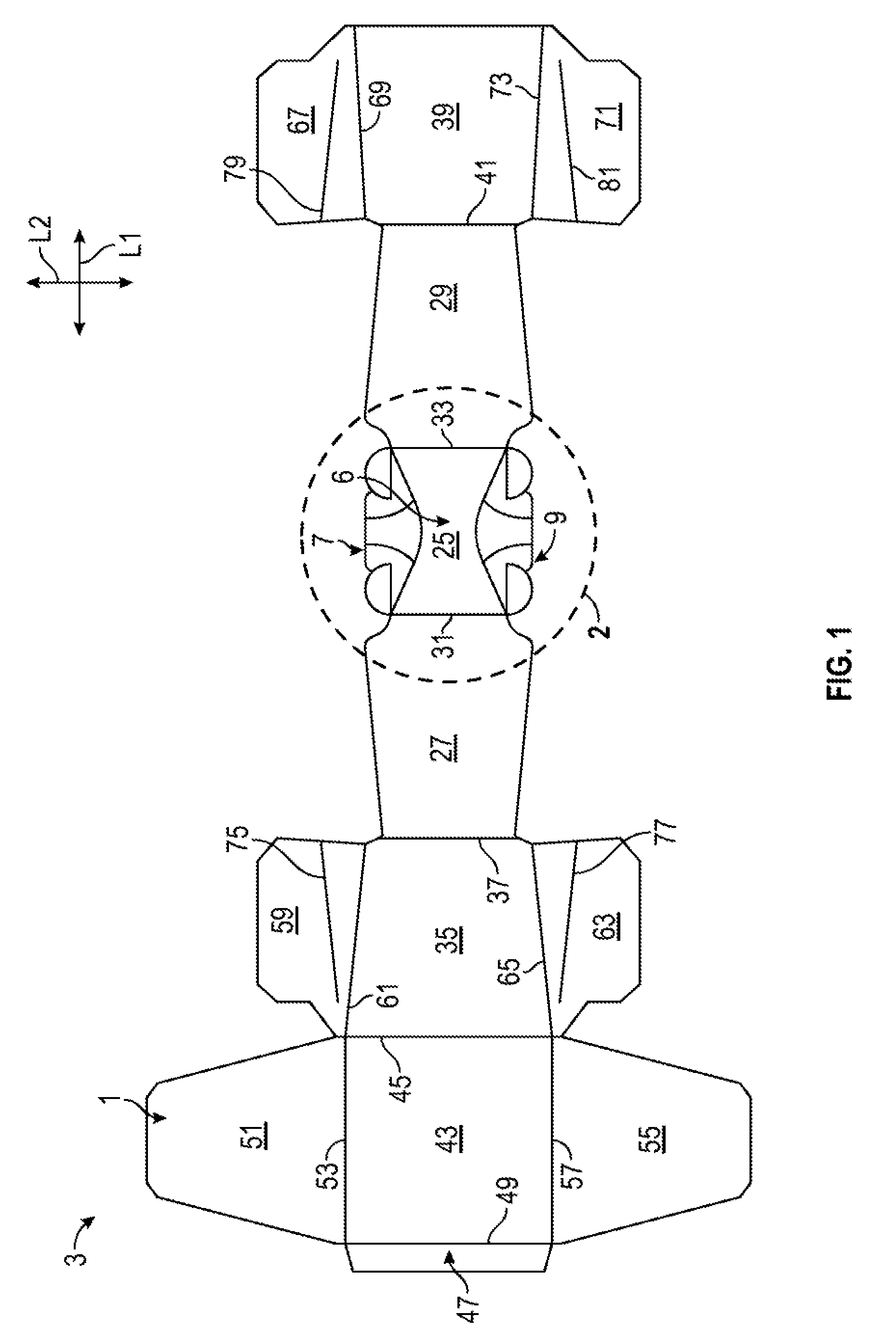
[0020] FIGS. 1 and 2 are plan views of an exterior surface 1 of a blank 3 that can be obtained for forming a carton or carrier 5 (FIG. 5) according to a first exemplary embodiment of the disclosure. The carrier 5 can be used to hold at least one article A (FIG. 4), such as beverage bottles or cans. As shown, the carrier 5 is provided with a handle 6 comprising handle features 7, 9 (broadly, respective "first handle features" and "second handle features") that are positionable to facilitate carrying of the carrier 5 by a user. It will be understood that one or both handle features 7, 9 can be provided without departing from the disclosure.
[0021] The blank 3, as shown, has a longitudinal axis L1 and a lateral axis L2. The blank 3 includes a top panel 25 with handle features 7, 9, as described further herein. As shown, the top panel 25 is foldably connected to a first upper side panel 27 and a second upper side panel 29 at respective lateral fold lines 31, 33. As shown, a first lower side panel 35 is foldably connected to the first upper side panel 27 at a lateral fold line 37, and a second lower side panel 39 is foldably connected to the second upper side panel 29 at a lateral fold line 41. As also shown, a bottom panel 43 is foldably connected to the first lower side panel 35 at a lateral fold line 45. An attachment flap 47 can be foldably attached to the bottom panel 43 at a lateral fold line 49, as shown.
[0022] As shown in FIG. 1, a first bottom end flap 51 is foldably connected to the bottom panel 43 at longitudinal fold line 53, and a second bottom end flap 55 is foldably connected to the bottom panel 43 at a longitudinal fold line 57. As also shown, a first side end flap 59 is foldably connected to the first lower side panel 35 at an oblique fold line 61, a second side end flap 63 is foldably connected to the first lower side panel 35 at an oblique fold line 65, a third side end flap 67 is foldably connected to the second lower side panel 39 at an oblique fold line 69, and a fourth side end flap 71 is foldably connected to the second lower side panel 39 at an oblique fold line 73. Respective oblique fold lines 75, 77, 79, 81, as shown, can extend from a respective free edge of the respective end flaps 59, 63, 67, 71 to an interior portion of the respective end flaps 59, 63, 67, 71. In this regard, the end flaps 51, 59, 67 extend along a first marginal area of the blank 3, and the end flaps 55, 63, 71 extend along a second marginal area of the blank 3.
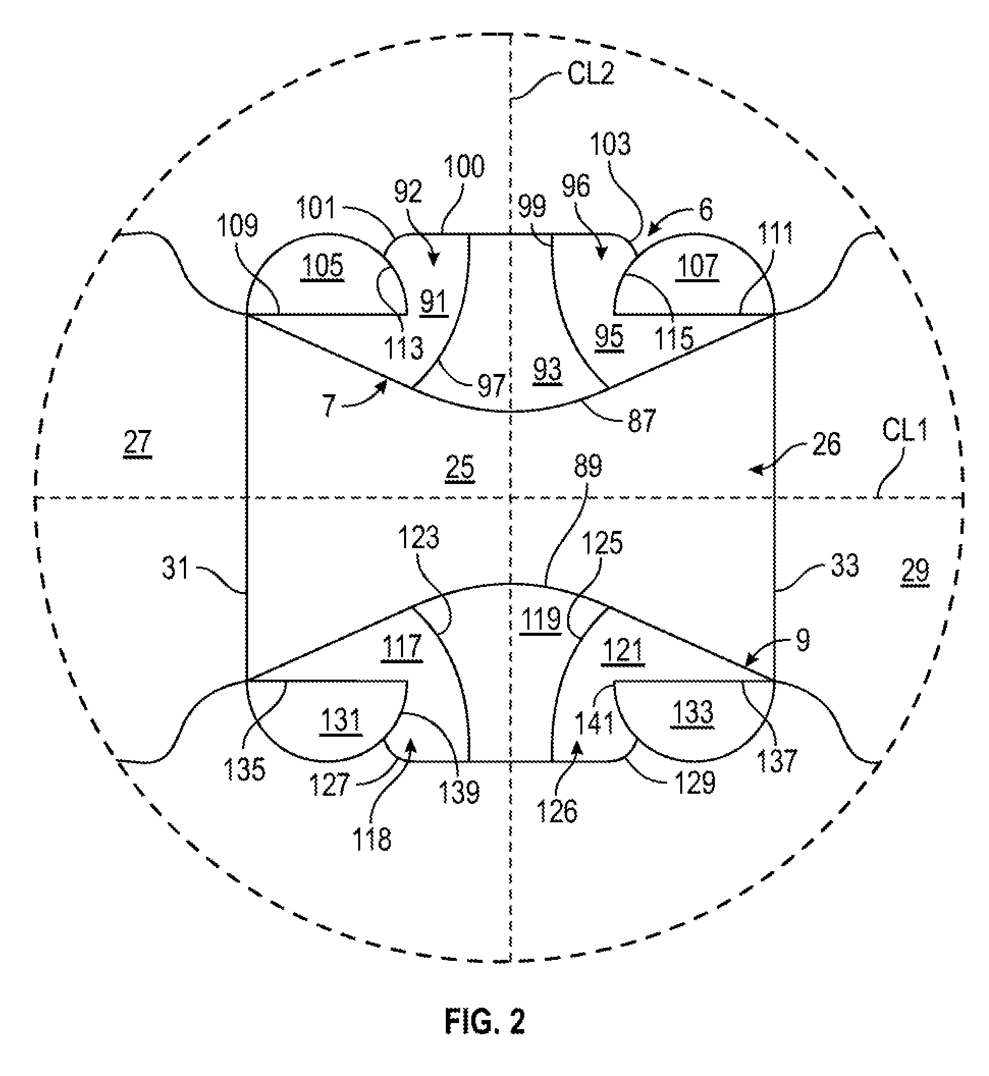
[0023] FIG. 2 illustrates the handle features 7, 9 of the top panel 25 in detail. As shown, each handle feature 7, 9 is at least partially defined by respective fold lines 87, 89 that have an at least partially curved configuration, as shown, and which each intersect the fold lines 31, 33 at respective endpoints thereof. In this regard, the respective handle features 7, 9 are formed between the respective fold lines 87, 89 and the respective free edges of the top panel 25. As shown, each of the fold lines 87, 89 may have a substantially convex configuration with regard to a longitudinal centerline CL1 of the top panel 25, e.g., each fold line 87, 89 extends toward its respective endpoints in a direction extending away from the longitudinal centerline CL1.
[0024] As shown, the handle feature 7 includes a plurality of handle portions or sections 91, 93, 95, with the central section 93 (broadly, "first central section") being centrally disposed between the two longitudinally marginal or outer sections 91 (broadly, "first outer section"), 95 (broadly, "second outer section"). As shown, the central section 93 is foldably connected to the outer section 91 at a curved fold line 97 (broadly, "first curved fold line") and the central section 93 is foldably connected to the outer section 95 at a curved fold line 99 (broadly, "second curved fold line"). In the illustrated embodiment, the curved fold lines 97, 99 each extend from the curved fold line 87 to a free edge of the top panel 25 such that the curved fold line 87 is a common curved fold line (broadly, "first common curved fold line") at which the central section 93 and the outer sections 91, 95 are foldably connected to a body portion 26 of the top panel 25. As shown, each of the outer sections 91, 95 includes laterally marginal portions 92, 96 thereof that present respective locking edges 101, 103. In the illustrated embodiment, each of the curved fold lines 97, 99 has a generally convex configuration with reference to a lateral centerline CL2 of the top panel 25, e.g., each curved fold line 97, 99 extends toward its respective endpoints in a direction extending away from the lateral centerline CL2. In this regard, and as shown, the central section 93 has a configuration that generally tapers from the fold line 87 to the free edge of the top panel 25.
[0025] Still referring to FIGS. 1 and 2, a first tab 105 is foldably connected to the outer section 91 at a longitudinal fold line 109 and a second tab 107 is foldably connected to the outer section 95 at a longitudinal fold line 111. In the illustrated embodiment, each tab 105, 107 has a semicircular configuration and is at least partially defined by curved cuts 113, 115 in the top panel 25 that separate the respective tabs 105, 107 from the respective marginal portions 92, 96 of the respective outer sections 91, 95 and at least partially define the respective locking edges 101, 103. The handle feature 7 could be otherwise shaped, arranged, and/or configured without departing from the disclosure.
[0026] The handle feature 9 can have similarly-configured features to the handle features 7 described above. In particular, the handle feature 9 includes a central section 119 (broadly, "second central handle section"), and two outer sections 117 (broadly, "third outer handle section"), 121 (broadly, "fourth outer handle section"), with the central section 119 foldably connected to the outer sections 117, 121 at a respective curved fold lines 123, 125 that are convex relative to the lateral centerline CL2. The sections 117, 119, 121 of handle feature 9 are each foldably connected to a portion of the curved fold line 89 such that the fold line 89 is a common curved fold line (broadly, "second common curved fold line"). Outer sections 117, 121 have respective marginal portions 118, 120 with respective locking edges 127, 129, and tabs 131, 133 are foldably connected to the respective outer sections 117, 121 at respective fold lines 135, 137. The locking edges 127, 129 are at least partially defined by and are at least partially separated from the respective tabs 131, 133 at respective curved cuts 139, 141. One or both of the handle features 7, 9 can be differently-configured without departing from the disclosure.
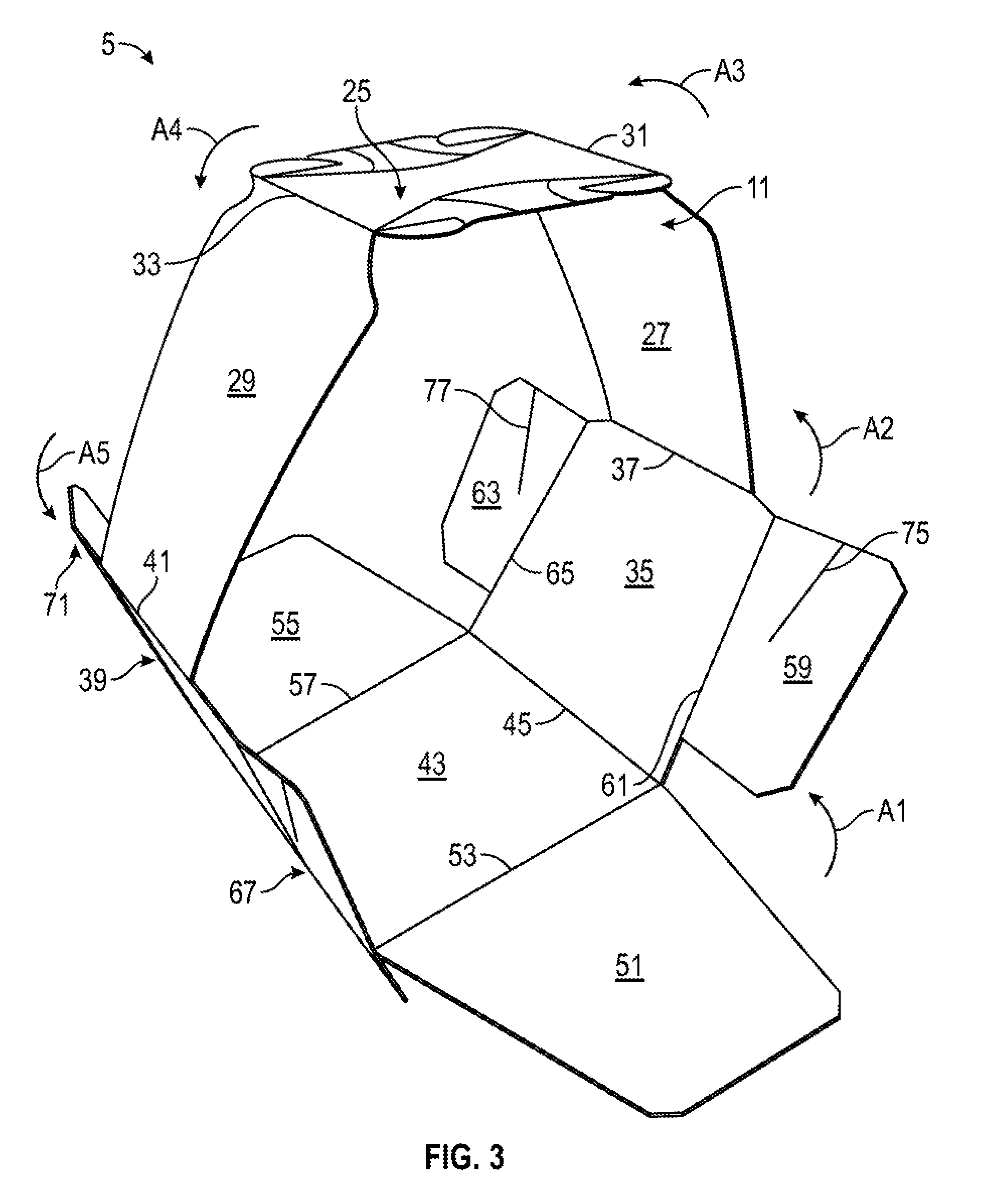
[0027] Turning additionally to FIGS. 3 and 4, the formation of the carrier 5 from the blank 3 according to one exemplary embodiment of the disclosure will be described. The panels 43, 35, 27, 25, 29, and 39 can be folded relative to one another at one or more of the fold lines 45, 37, 31, 33, and 41 in the direction of the respective arrows A1, A2, A3, A4, A5 such that the panels 43, 35, 27, 25, 29, 39 extend at least partially around an interior 11 of the carrier 5. The attachment flap 47 can be folded at the fold line 49 and placed in at least partial overlapping relation, e.g., at least partial face-to-face contact, with the second lower side panel 39, and can be secured thereto, for example, with an adhesive such as glue. As shown, the top panel 25 and the bottom panel 43 can be disposed in substantially parallel spaced relation, with the respective first upper side panel and first lower side panel 27, 35 and the respective second upper side panel and second lower side panel 29, 39 extending between the top panel 25 and the bottom panel 43. As shown, the respective upper side panels 27, 29 may be obliquely disposed relative to the respective lower side panels 35, 39. Such an arrangement can be facilitated by, for example, the presence of one or more articles A (shown in FIG. 4) in the carrier 5. In the illustrated partially-formed configuration of the carrier 5, a sleeve-like arrangement is provided within which one or more articles A, e.g., beverage containers, can be inserted into the interior 11 of the carrier 5. Alternatively, the carrier 5 can be formed by wrapping the blank 3 around the group of articles A to be contained in the interior.
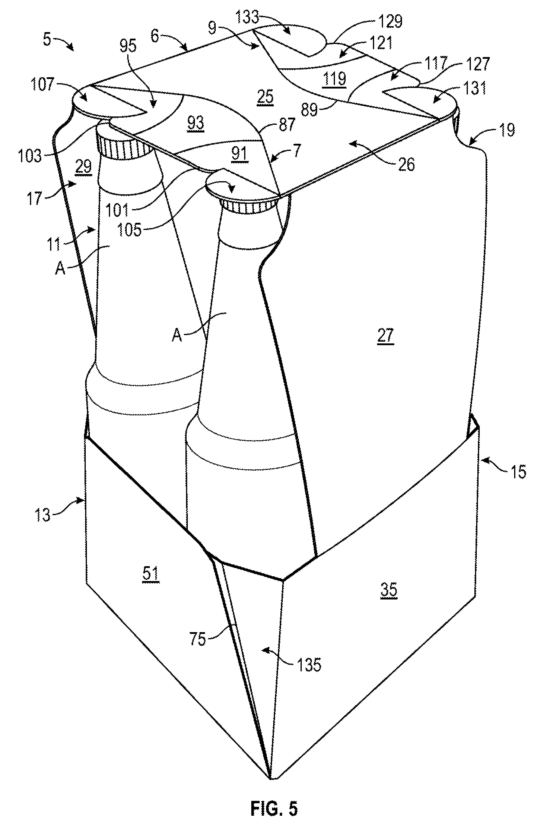
[0028] Still referring to FIGS. 3 and 4, and referring additionally to FIG. 5, once a desired number of articles A are loaded into the interior 11 of the carrier 5, the side end flaps 59, 67 can be folded at respective fold lines 61, 69 toward one another in the direction of the respective arrows A6, A7 into at least partial overlapping relation to at least partially close a first end 13 of the carrier 5. Similarly, the side end flaps 63, 71 can be folded toward each other at respective fold lines 65, 73 into at least partial overlapping relation to at least partially close a second end 15 of the carrier 5. As shown, one or more of the side end flaps 59, 67, 63, 71 may at least partially fold at respective fold lines 75, 79, 77, 81, for example, in at least partial engagement of one or more articles A disposed in the carrier 5, such that the carrier 5 can be provided with one or more shaped corner sections 135 formed by relative folding of portions of the respective side flaps 59, 63, 67, 71 at the respective oblique fold lines 75, 77,79, 81. The corner sections 135 can have a configuration that is, for example, obliquely-angled, curved, rounded, or chamfered, to name a few. The bottom end flaps 51, 55 can then be folded upwardly at the respective fold lines 53, 57 into at least partial overlapping relation with the respective side end flaps 59, 67 and 63, 71.
[0029] In this regard, and as shown, each end 13, 15 of the carrier 5 defines a respective opening 17, 19 along an upper portion thereof into the interior 11 of the carrier 5, for example, to view portions of one or more articles A (such as to provide graphics and/or labeling that includes marketing, pricing, and/or other identifying or descriptive information) and/or to access portions of the one or more articles A, for example, to facilitate removal thereof from the carrier 5.
[0030] Referring additionally to FIG. 6, a user can engage the handle 6 by activating one or both of the handle features 7, 9 to facilitate carrying of the carrier 5. As shown, the handle features 7, 9 are regions of the carrier 5 that are configured to at least partially deform, e.g., bend, crush, crumple, and/or fold, in order to present one or more surfaces that facilitate engagement by a user, for example, a user's fingers. As shown, the respective sections 91, 93, 95 and 117, 119, 121 are configured for relative movement to one another such that the respective handle features 7, 9 deform downwardly or inwardly, e.g., toward and/or at least partially into the interior 11 of the carrier 5. In the activated position of the handle 6, the handle features 7, 9 can deform into respective substantially concave recesses relative to the body portion 26 of the top panel 25. The respective locking edges 101, 103 and 127, 129 of the respective handle sections 91, 95, 117, 121 can engage portions of the articles A, for example, ridges of caps C of the articles A, to lock or otherwise maintain the handle features 7, 9 in the activated position. In addition, the tabs 105, 107, 131, 133 are configured to be positioned in overlying face-to-face contact with the caps C of the articles A when the handle 6 is activated. In one embodiment, the tabs 105, 107, 131, 133 can provide a barrier between a portion of a user, for example, the fingers of a user's hand, and one or more articles A in the interior 11 of the carrier 5.
[0031] In one configuration, as shown, the central section 93 of the handle feature 7 can be pressed downwardly to at least partially fold at the fold line 87 into substantially oblique or substantially perpendicular arrangement with the body portion 26 of the top panel 25. Such movement of the central section 93 causes the respective outer sections 91, 95 to become downwardly disposed relative to the body portion 26 of the top panel 25 and obliquely disposed relative to the central section 93 by folding at the respective fold line 87 and the curved fold line 97, and at the fold line 87 and the curved fold line 99, respectively, to form the recessed configuration of the handle 6. In such an arrangement, locking edges 101, 103 can engage ridges in the caps C of the articles A to lock or maintain the arrangement of the handle feature 7 in the activated position. In such a configuration of the handle feature 7, the sections 91, 93, 95 may engage a portion of a user's fingers, for example, by at least partially hugging, clamping, and/or clasping around a user's fingers in a non-injurious fashion, such that the user is provided with a comfortable and secured engagement of the carrier 5 upon engagement of the handle feature 7. The tabs 105, 107 are positioned to rest upon the caps C of the articles A as described above. In this regard, the handle feature 7 is configured to transition between a first, substantially flat configuration, and a second, activated or substantially recessed configuration as described above.
[0032] The handle feature 9 can be engaged and activated by a user from a first, flat configuration to a second, recessed configuration in a similar manner as described above with respect to the handle feature 7, for example, so that the central section 119 is pressed downwardly to at least partially fold at the fold line 89 into substantially oblique or substantially perpendicular arrangement with the body portion 26 of the top panel 25, and with the outer sections 117, 119 downwardly disposed relative to the body portion 26 of the top panel 25 and obliquely disposed relative to the central section 103 by folding at the respective fold line 89 and the curved fold line 123 and at the fold line 89 and the curved fold line 125 to form the recessed configuration of the handle 6. The locking edges 127, 129 can engage ridges in the caps C of the articles A to lock or maintain the handle feature 9 in an activated position. In the activated position, the respective tabs 131, 133 are positioned to rest upon the caps C of the articles A as described above with respect to the handle feature 7. In the activated position of the handle 6, the body portion 26 of the top panel 25 between the fold lines 87, 89 can be generally arched upwardly between the side panels 27, 29 to facilitate grasping the handle 6, for example, by contacting a portion of a user's hand.
[0033] It will be understood that one or both of the handle features 7, 9 can have a different pattern of deformation, or that the patterns of deformation described above can occur differently, e.g., in a different order, without departing from the disclosure.
[0034] Turning now to FIGS. 7 and 8, an exterior surface 201 of a blank 203 that can be obtained for forming carton or carrier 205 (FIG. 9) according to a second exemplary embodiment of the disclosure is illustrated. The blank 203 and the carrier 205 may have similar features to the blank 3 (FIG. 1) and the carrier 5 (FIG. 5) described above, and like or similar reference numbers are used to designate like or similar features.
[0035] As shown, the blank 203 includes a top panel 225 having a handle 206 comprising handle features 207, 209. FIG. 8 illustrates the handle features 207, 209 of the top panel 225 in detail. As shown, each of the handle features 207, 209 is at least partially defined by a respective curved edge 283, 285 that form respective portions of respective free edges of the top panel 225. As also shown, each handle feature 207, 209 is also at least partially defined by respective fold lines 287, 289 that can have a curved configuration, as shown, and which have respective endpoints that intersect the respective curved edges 283, 285. As shown, the fold lines 287, 289 each have a generally convex configuration relative to a longitudinal centerline CL3 of the top panel 225, e.g., each fold line 287, 289 extends toward respective endpoints in a direction extending away from the longitudinal centerline CL3.
[0036] As shown, the handle feature 207 includes a plurality of sections 291, 293, 295, with the central section 293 (broadly, "first central section") being centrally disposed between longitudinally marginal or outer sections 291 (broadly, "first outer section"), 295 (broadly, "second outer section"). As shown, the central section 293 is foldably connected to the outer section 291 at a curved fold line 297 and the central section 293 is foldably connected to the outer section 295 at a curved fold line 299. In the illustrated embodiment, the curved fold lines 297, 299 each extend between the curved edge 283 and the fold line 287 such that the fold line 287 is a common curved fold line (broadly, "first common fold line") at which each of the sections 291, 293, 295 are foldably connected to a body portion 226 of the top panel 225. As shown, each of the curved fold lines 297, 299 has a generally convex configuration relative to a lateral centerline CL4 of the top panel 225, e.g., each curved fold line 297, 299 extends toward respective endpoints in a direction extending away from the lateral centerline CL4. In this regard, and as shown, the central section 293 has a configuration that generally tapers from the fold line 287 to the curved edge 283. In the illustrated embodiment, the outer sections 291, 293 are defined by a portion of the curved edge 283, a portion of the curved fold line 287 and a respective curved fold line 297, 299. The sections 291, 293, 295 could be otherwise shaped, arranged, and/or configured without departing from the disclosure.
[0037] Still referring to FIGS. 7 and 8, the handle features 209 can have similarly-configured features to the handle features 207 described above. In particular, the handle features 209 include a central section 303 (broadly, "second central section"), and longitudinally marginal or outer sections 301 (broadly, "third outer section"), 305 (broadly, "fourth outer section"), with the central section 303 foldably connected to the outer sections 301, 305 at a respective curved fold lines 307, 309, and each of the sections 301, 303, 305 foldably connected to the body portion 226 of the top panel 225 at the curved fold line 289 such that the curved fold line 289 is a common curved fold line (broadly, "second common curved fold line). One or both of the handle features 207, 209 can be differently-configured without departing from the disclosure. The sections 301, 303, 305 are defined by the fold lines 289, 307, 309 and the curved edge 285 of the top panel 225.
[0038] Turning additionally to FIGS. 9 and 10, the carrier 205 can be formed in a similar manner as described above with respect to the carrier 5 (FIG. 5). As shown, a user can engage the handle 206 at one or both of the handle features 207, 209 to facilitate carrying of the carrier 205. As shown, the handle features 207, 209 are regions of the carrier 205 that are configured to at least partially deform, e.g., bend, crush, crumple, and/or fold, in order to present one or more surfaces that facilitate engagement by a user, for example, a user's fingers. As shown, the respective sections 291, 293, 295 and 301, 303, 305 are configured for relative movement to one another such that the respective handle features 207, 209 deform downwardly or inwardly, e.g., toward and/or at least partially into the interior 11 of the carrier 205. In this regard, in the activated position of the handle 206, the handle features 307, 309 can deform into respective substantially concave recesses relative to the body portion 226 of the top panel 225.
[0039] In one configuration, as shown, the central section 293 of the handle feature 207 can be pressed downwardly or inwardly to at least partially fold at the fold line 287 into substantially oblique or substantially perpendicular arrangement with the body portion 226 of the top panel 225. Such movement of the central section 293 causes the respective outer sections 291, 295 to become downwardly disposed relative to the body portion 226 of the top panel 225 and obliquely disposed relative to the central section 293 by folding at the respective fold line 287 and the curved fold line 297, and at the fold line 287 and the curved fold line 299, respectively, to form the recessed configuration of the handle 206. In the activated configuration of the handle 206, the sections 291, 293, 295 may engage a portion of a user's fingers, for example, by at least partially hugging, clamping, and/or clasping around a user's fingers in a non-injurious fashion, such that the user is provided with a secured engagement of the carrier 205 upon engagement of the handle feature 207. In this regard, the handle feature 207 is configured to transition between a first, substantially flat configuration, and a second, activated configuration as described above.
[0040] The handle feature 209 of the handle 206 can be engaged and activated by a user from a first, flat configuration to a second, activated configuration in a similar manner as described above with respect to the handle feature 207, for example, so that the central section 303 is pressed downwardly to at least partially fold at the fold line 289 into substantially oblique or substantially perpendicular arrangement with the body portion 226 of the top panel 225, and with the sections 301, 305 downwardly disposed relative to the top panel 225 and obliquely disposed relative to the section 303 by folding at the respective fold line 289 and the curved fold line 307, and at the fold line 289 and the curved fold line 309, respectively, to form the recessed configuration of the handle 206. In the activated position of the handle 206, the body portion 226 of the top panel 225 is generally arched upwardly between the side panels 27, 29 to facilitate grasping the handle 206, for example, by contacting the palm of a user's hand.
[0041] It will be understood that one or both of the handle features 207, 209 of the handle 206 can have a different pattern of deformation, or that the patterns of deformation described above can occur differently, e.g., in a different order, without departing from the disclosure.
[0042] As described herein, the handle features 207, 209 provide the carrier 205 with an at least partially deformable structure that provides one or more engagement surfaces for carrying of the carrier 205. Following an initial deformation of the handle features 207, 209 as described above, the handle 206 may be configured to remain in such deformed or activated configuration for subsequent use, for example, due to the engagement of one or both of the edges 283, 285 with respective portions of the articles A, e.g., the caps C. In one embodiment, one or both of the handle features 207, 209 can have, an at least partially resilient configuration, for example, such that one or both of the handle features 207, 209 can be biased or otherwise configured to return from a deformed or activated position to a non-deformed or flat configuration.
[0043] The blanks according to the present disclosure can be, for example, formed from coated paperboard and similar materials. For example, the interior and/or exterior sides of the blanks can be coated with a clay coating. The clay coating may then be printed over with product, advertising, price coding, and other information or images. The blanks may then be coated with a varnish to protect any information printed on the blank. The blanks may also be coated with, for example, a moisture barrier layer, on either or both sides of the blank. In accordance with the above-described embodiments, the blanks may be constructed of paperboard of a caliper such that it is heavier and more rigid than ordinary paper. The blanks can also be constructed of other materials, such as cardboard, hard paper, or any other material having properties suitable for enabling the carrier to function at least generally as described herein. The blanks can also be laminated or coated with one or more sheet-like materials at selected panels or panel sections.
[0044] In accordance with the above-described embodiments of the present disclosure, a fold line can be any substantially linear, although not necessarily straight, form of weakening that facilitates folding there along. More specifically, but not for the purpose of narrowing the scope of the present disclosure, fold lines include: a score line, such as lines formed with a blunt scoring knife, or the like, which creates a crushed portion in the material along the desired line of weakness; a cut that extends partially into a material along the desired line of weakness, and/or a series of cuts that extend partially into and/or completely through the material along the desired line of weakness; and various combinations of these features.
[0045] As an example, a tear line can include: a slit that extends partially into the material along the desired line of weakness, and/or a series of spaced apart slits that extend partially into and/or completely through the material along the desired line of weakness, or various combinations of these features. As a more specific example, one type tear line is in the form of a series of spaced apart slits that extend completely through the material, with adjacent slits being spaced apart slightly so that a nick (e.g., a small somewhat bridging-like piece of the material) is defined between the adjacent slits for typically temporarily connecting the material across the tear line. The nicks are broken during tearing along the tear line. The nicks typically are a relatively small percentage of the tear line, and alternatively the nicks can be omitted from or torn in a tear line such that the tear line is a continuous cut line. That is, it is within the scope of the present disclosure for each of the tear lines to be replaced with a continuous slit, or the like. For example, a cut line can be a continuous slit or could be wider than a slit without departing from the present disclosure.
[0046] The above embodiments may be described as having one or more panels adhered together by glue during erection of the carton or carrier embodiments. The term "glue" is intended to encompass all manner of adhesives commonly used to secure carton or carrier panels in place.
[0047] The foregoing description of the disclosure illustrates and describes various exemplary embodiments. Various additions, modifications, changes, etc., could be made to the exemplary embodiments without departing from the spirit and scope of the disclosure. It is intended that all matter contained in the above description or shown in the accompanying drawings shall be interpreted as illustrative and not in a limiting sense. Additionally, the disclosure shows and describes only selected embodiments of the disclosure, but the disclosure is capable of use in various other combinations, modifications, and environments and is capable of changes or modifications within the scope of the inventive concept as expressed herein, commensurate with the above teachings, and/or within the skill or knowledge of the relevant art. Furthermore, certain features and characteristics of each embodiment may be selectively interchanged and applied to other illustrated and non-illustrated embodiments of the disclosure.
* * * * *
D00000
D00001
D00002
D00003
D00004
D00005
D00006
D00007
D00008
D00009
D00010
XML
uspto.report is an independent third-party trademark research tool that is not affiliated, endorsed, or sponsored by the United States Patent and Trademark Office (USPTO) or any other governmental organization. The information provided by uspto.report is based on publicly available data at the time of writing and is intended for informational purposes only.
While we strive to provide accurate and up-to-date information, we do not guarantee the accuracy, completeness, reliability, or suitability of the information displayed on this site. The use of this site is at your own risk. Any reliance you place on such information is therefore strictly at your own risk.
All official trademark data, including owner information, should be verified by visiting the official USPTO website at www.uspto.gov. This site is not intended to replace professional legal advice and should not be used as a substitute for consulting with a legal professional who is knowledgeable about trademark law.