Carton with Tamper Resistant Features
Zammit; Mark ; et al.
U.S. patent application number 16/371237 was filed with the patent office on 2019-07-25 for carton with tamper resistant features. The applicant listed for this patent is Graphic Packaging International, LLC. Invention is credited to Elias Spartis, Mark Zammit.
| Application Number | 20190225397 16/371237 |
| Document ID | / |
| Family ID | 54768982 |
| Filed Date | 2019-07-25 |


View All Diagrams
| United States Patent Application | 20190225397 |
| Kind Code | A1 |
| Zammit; Mark ; et al. | July 25, 2019 |
Carton with Tamper Resistant Features
Abstract
A carrier for holding a plurality of containers. The carrier has a bottom panel, at least one front panel, at least one back panel, at least two side panels, and at least one central panel dividing the interior of the carrier into a front portion and a back portion. At least one front divider flap is foldably connected to the at least one central panel and at least one back divider flap is foldably connected to the at least one central panel. At least one retention flap is foldably connected to at least one of the at least one front panel, the at least one back panel, the at least two side panels, and the at least one central panel. The at least one retention flap engages a container and provides stability to the respective container in one of the front or back container-receiving spaces.
| Inventors: | Zammit; Mark; (Douglasville, GA) ; Spartis; Elias; (Roswell, GA) | ||||||||||
| Applicant: |
|
||||||||||
|---|---|---|---|---|---|---|---|---|---|---|---|
| Family ID: | 54768982 | ||||||||||
| Appl. No.: | 16/371237 | ||||||||||
| Filed: | April 1, 2019 |
Related U.S. Patent Documents
| Application Number | Filing Date | Patent Number | ||
|---|---|---|---|---|
| 14733238 | Jun 8, 2015 | 10287073 | ||
| 16371237 | ||||
| 61997789 | Jun 10, 2014 | |||
| Current U.S. Class: | 1/1 |
| Current CPC Class: | B65D 2571/0066 20130101; B65D 2571/00141 20130101; B65D 2571/00802 20130101; B65D 2571/00956 20130101; B65D 2571/00475 20130101; B65D 2571/00314 20130101; B65D 71/0022 20130101 |
| International Class: | B65D 71/58 20060101 B65D071/58 |
Claims
1. A blank for forming a carrier for holding a plurality of containers, the blank comprising: a plurality of panels, the plurality of panels comprising a bottom panel, at least one front panel, at least one back panel, at least two side panels, and at least one central panel for dividing the interior of the carrier into a front portion and a back portion when the carrier is formed from the blank, the at least one front panel comprising at least a first front panel and a second front panel; at least one front divider flap foldably connected to the at least one central panel and configured to extend to the first front panel to divide the front portion into at least one front container-receiving space when the carrier is formed from the blank, at least one back divider flap foldably connected to the at least one central panel and configured to extend to the at least one back panel to divide the back portion into at least one back container-receiving space when the carrier is formed from the blank, at least one retention flap foldably connected to at least one of the at least one front panel, the at least one back panel, the at least two side panels, and the at least one central panel, the at least one retention flap is configured to engage a respective container of the plurality of containers and provide stability to the respective container in one of the at least one front container-receiving space and at least one back container-receiving space when the carrier is formed from the blank; wherein the at least one retention flap comprises at least a first retention flap foldably connected to the at least one back panel and a second retention flap foldably connected to the second front panel, and the second front panel is for being spaced apart from the at least one back panel by the back portion when the carrier is formed from the blank; wherein the at least one front container-receiving space and the at least one back container-receiving space are for being substantially open along a top edge of the carrier formed from the blank when the at least one retention flap engages the respective container of the plurality of containers.
2. The blank of claim 1, wherein the at least one retention flap comprises an aperture configured to receive a top portion of the respective container of the plurality of containers when the carrier is formed from the blank.
3. The blank of claim 2, wherein the at least one retention flap comprises a base portion foldably connected to one of the at least one front panel, the at least one back panel, the at least two side panels, and the at least one central panel and a distal portion foldably connected to the base portion, the distal portion comprises the aperture.
4. The blank of claim 3, wherein the distal portion comprises a plurality of tabs adjacent the aperture, the plurality of tabs being defined by cuts extending from the aperture.
5. The blank of claim 1, wherein the at least one back panel comprises a first back panel and a second back panel, and the at least two side panels comprise a first side panel, a second side panel, a third side panel, and a fourth side panel, the first front panel is foldably connected to the first side panel at a first fold line and the second side panel at a second fold line, the second front panel is foldably connected to the second side panel at a third fold line; the first back panel is foldably connected to the third side panel at a fourth fold line and the second back panel at a fifth fold line, the second back panel is foldably connected to the fourth side panel at a sixth fold line.
6. The blank of claim 5, wherein the at least one retention flap further comprises a third retention flap, the first retention flap is foldably connected to the first back panel, the second retention flap is foldably connected to the second front panel, and the third retention flap is foldably connected to the second side panel.
7. The blank of claim 5, wherein the at least one container-receiving space comprises a first container-receiving space, a second container-receiving space, and a third container-receiving space when the carrier is formed from the blank.
8. The blank of claim 7, further comprising a first handle aperture in the second side panel and the second front panel, and a second handle aperture in the first central panel, the first handle aperture is configured to align with the second handle aperture when the carrier is formed from the blank.
9. The blank of claim 8, further comprising a third handle aperture at least partially in the second back panel and the fourth side panel, and a fourth handle aperture in the second central panel, the third handle aperture is configured to align with the fourth handle aperture when the carrier is formed from the blank.
10. The blank of claim 9, further comprising a fifth handle aperture in the first front panel and the first side panel, at least a portion of the first handle aperture, the second handle aperture, the third handle aperture, the fourth handle aperture and the fifth handle aperture are configured to align and form a handle opening in the carrier when the carrier is formed from the blank.
11. The blank of claim 7, wherein the first front panel, first side panel, and the at least one front divider flap are configured to form the first container-receiving space, the first back panel, third side panel, and the at least one back divider flap are configured to form the second container-receiving space, and the second back panel, fourth side panel, and the at least one back divider flap are configured to form the third container-receiving space when the carrier is formed from the blank.
12. The blank of claim 11, wherein the at least one retention flap further comprises a third retention flap, the first article retention flap is foldably connected to the first back panel, the second article retention flap is foldably connected to the second front panel, and the third article retention flap is foldably connected to the second side panel.
13. A method of forming a carrier for holding a plurality of containers, the method comprising: obtaining a blank comprising a bottom panel, at least one front panel, at least one back panel, at least two side panels, and at least one central panel, at least one front divider flap foldably connected to the at least one central panel, at least one back divider flap foldably connected to the at least one central panel, and at least one retention flap foldably connected to at least one of the at least one front panel, the at least one back panel, the at least two side panels, and the at least one central panel, the at least one front panel comprising at least a first front panel and a second front panel, the at least one retention flap comprising at least a first retention flap foldably connected to the at least one back panel and a second retention flap foldably connected to the second front panel, forming the interior, dividing the interior into a front portion and a back portion with the at least one central panel so that the second front panel is spaced apart from the at least one back panel by the back portion, dividing the front portion into at least one front container-receiving space by positioning the at least one front divider flap so that the at least one front divider flap extends to the first front panel and dividing the back portion into at least one back container-receiving space by positioning the at least one back divider flap so that the at least one back divider flap extends to the at least one back panel, and engaging the at least one retention flap with a respective container of the plurality of containers, wherein the at least one front container-receiving space and the at least one back container-receiving space are substantially open along a top edge of the carrier after the engaging the at least one retention flap with the respective container.
14. The method of claim 13, wherein the at least one retention flap comprises an aperture for receiving a top portion of the respective container of the plurality of containers.
15. The method of claim 14, wherein the at least one retention flap comprises a base portion foldably connected to one of the at least one front panel, the at least one back panel, the at least two side panels, and the at least one central panel and a distal portion foldably connected to the base portion, the distal portion comprises the aperture.
16. The method of claim 15, wherein the distal portion comprises a plurality of tabs adjacent the aperture, the plurality of tabs being defined by cuts extending from the aperture.
17. The method of claim 13, wherein the at least one retention flap is foldably connected at the top edge of the carrier.
18. The method of claim 13, wherein the at least one back panel comprises a first back panel and a second back panel, and the at least two side panels comprise a first side panel, a second side panel, a third side panel, and a fourth side panel, the first front panel is foldably connected to the first side panel at a first fold line and the second side panel at a second fold line, the second front panel is foldably connected to the second side panel at a third fold line; the first back panel is foldably connected to the third side panel at a fourth fold line and the second back panel at a fifth fold line, the second back panel is foldably connected to the fourth side panel at a sixth fold line.
19. The method of claim 18, wherein the at least one retention flap further comprises a third retention flap, the first retention flap is foldably connected to the first back panel, the second retention flap is foldably connected to the second front panel, and the third retention flap is foldably connected to the second side panel.
20. The method of claim 18, wherein the at least one container-receiving space comprises a first container-receiving space, a second container-receiving space, and a third container-receiving space.
21. The method of claim 20, wherein the blank further comprises a first handle aperture in the second side panel and the second front panel, and a second handle aperture in the first central panel; and the method further comprises aligning the first handle aperture with the second handle aperture.
22. The method of claim 21, wherein the blank further comprises a third handle aperture at least partially in the second back panel and the fourth side panel, and a fourth handle aperture in the second central panel; and the method further comprises aligning the third handle aperture with the fourth handle aperture.
23. The method of claim 22, wherein the blank further comprises a fifth handle aperture in the first front panel and the first side panel, and the method further comprises aligning at least a portion of the first handle aperture, the second handle aperture, the third handle aperture, the fourth handle aperture and the fifth handle aperture and forming a handle opening in the carrier.
24. The method of claim 20, further comprising forming the first container-receiving space with the first front panel, first side panel, and the at least one front divider flap, forming the second container-receiving space with the first back panel, third side panel, and the at least one back divider flap, and forming the third container-receiving space with the second back panel, fourth side panel, and the at least one back divider flap.
25. The method of claim 24, wherein the at least one retention flap further comprises a third retention flap, the first article retention flap is foldably connected to the first back panel, the second article retention flap is foldably connected to the second front panel, and the third article retention flap is foldably connected to the second side panel.
Description
CROSS-REFERENCE TO RELATED APPLICATIONS
[0001] This application is a division of U.S. patent application Ser. No. 14/733,238, filed Jun. 8, 2015, which claims the benefit of U.S. Provisional Patent Application No. 61/997,789, filed Jun. 10, 2014.
INCORPORATION BY REFERENCE
[0002] The disclosures of U.S. patent application Ser. No. 14/733,238, which was filed Jun. 8, 2015, and U.S. Provisional Patent Application No. 61/997,789, which was filed Jun. 10, 2014, are hereby incorporated by reference as if presented herein in their entirety.
BACKGROUND OF THE DISCLOSURE
[0003] The present disclosure generally relates to carriers or cartons for holding and displaying containers. More specifically, the present disclosure relates to a carton having tamper resistant features.
SUMMARY OF THE DISCLOSURE
[0004] In general, one aspect of the disclosure is directed to a carrier for holding a plurality of containers. The carrier has a plurality of panels that extend at least partially around an interior of the carrier. The plurality of panels include a bottom panel, at least one front panel, at least one back panel, at least two side panels, and at least one central panel dividing the interior of the carrier into a front portion and a back portion. At least one front divider flap is foldably connected to the at least one central panel and extending to the at least one front panel to divide the front portion into at least one front container-receiving space. At least one back divider flap is foldably connected to the at least one central panel and extending to the at least one back panel to divide the back portion into at least one back container-receiving space. At least one retention flap foldably connected to at least one of the at least one front panel, the at least one back panel, the at least two side panels, and the at least one central panel. The at least one retention flap engages a respective container of the plurality of containers and provides stability to the respective container in one of the at least one front container-receiving space and at least one back container-receiving space.
[0005] In another aspect, the disclosure is generally directed to a blank for forming a carrier for holding a plurality of containers. The blank includes a plurality of panels. The plurality of panels include a bottom panel, at least one front panel, at least one back panel, at least two side panels, and at least one central panel for dividing the interior of the carrier into a front portion and a back portion when the carrier is formed from the blank. At least one front divider flap is foldably connected to the at least one central panel and configured to extend to the at least one front panel to divide the front portion into at least one front container-receiving space when the carrier is formed from the blank. At least one back divider flap is foldably connected to the at least one central panel and configured to extend to the at least one back panel to divide the back portion into at least one back container-receiving space when the carrier is formed from the blank. At least one retention flap foldably connected to at least one of the at least one front panel, the at least one back panel, the at least two side panels, and the at least one central panel. The at least one retention flap is configured to engage a respective container of the plurality of containers and provide stability to the respective container in one of the at least one front container-receiving space and at least one back container-receiving space when the carrier is formed from the blank.
[0006] In another aspect, the disclosure is generally directed to a method of forming a carrier for containing a plurality of containers. The method includes obtaining a blank having a bottom panel, at least one front panel, at least one back panel, at least two side panels, and at least one central panel. At least one front divider flap is foldably connected to the at least one central panel, at least one back divider flap foldably connected to the at least one central panel, and at least one retention flap is foldably connected to at least one of the at least one front panel, the at least one back panel, the at least two side panels, and the at least one central panel. The method further includes forming the interior, dividing the interior into a front portion and a back portion with the at least one central panel, and dividing the front portion into at least one front container-receiving space by positioning the at least one front divider flap so that the at least one divider flap extends to the front panel and dividing the back portion into at least one back container receiving space by positioning the at least one back divider flap so that the at least one back divider flap extends to the back panel. The method further includes engaging the at least one retention flap with a respective container of the plurality of containers.
BRIEF DESCRIPTION OF THE DRAWINGS
[0007] Those skilled in the art will appreciate the above stated advantages and other advantages and benefits of various additional embodiments reading the following detailed description of the embodiments with reference to the below-listed drawing figures. It is within the scope of the present disclosure that the above-discussed aspects be provided both individually and in various combinations.
[0008] According to common practice, the various features of the drawings discussed below are not necessarily drawn to scale. Dimensions of various features and elements in the drawings may be expanded or reduced to more clearly illustrate the embodiments of the disclosure.
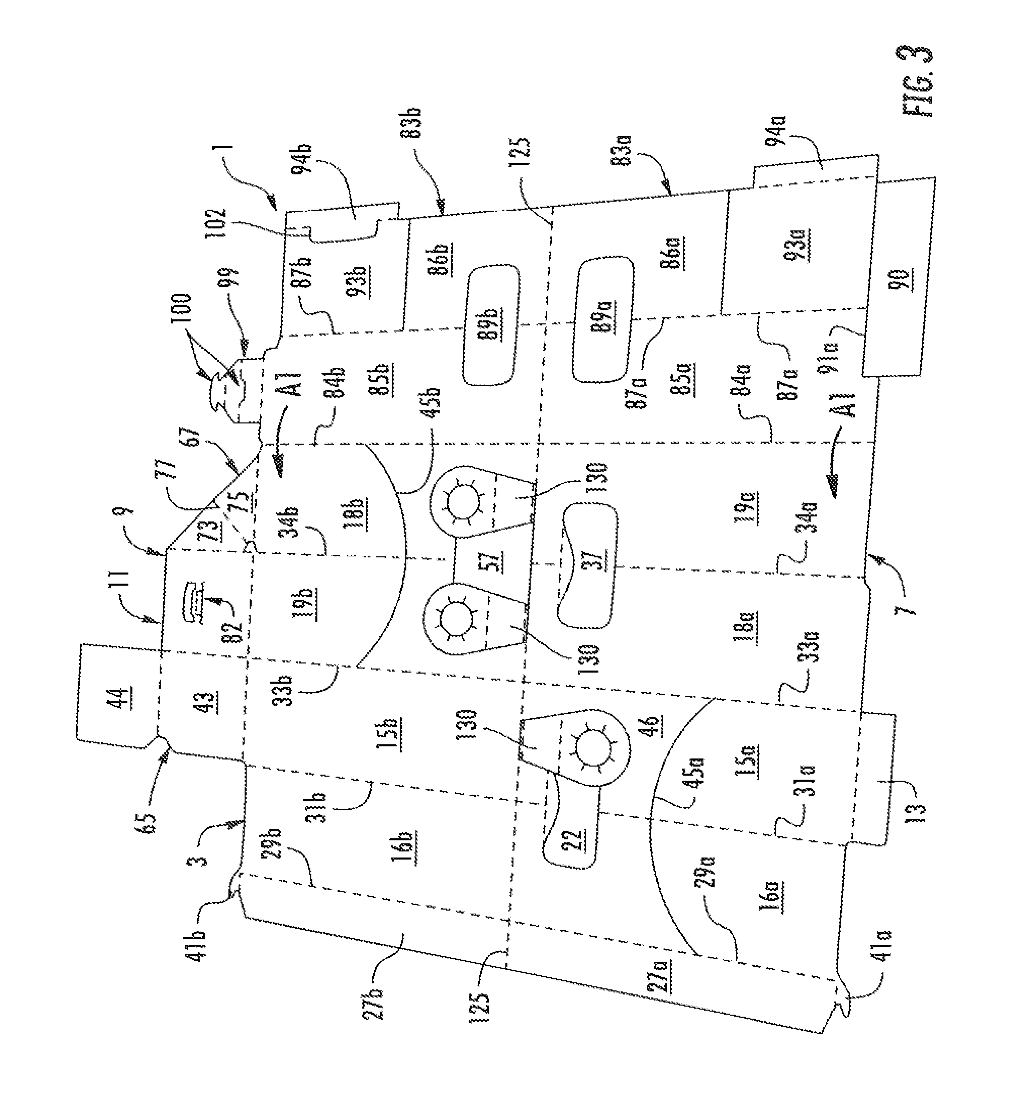
[0009] FIG. 1 is a plan view of an exterior of a carton blank used to form an exemplary basket-style carrier according to one embodiment of the disclosure.
[0010] FIG. 2 is a detailed view of the tamper resistant features according to one embodiment of the disclosure.
[0011] FIG. 3 is a perspective view of the interior of the carton blank of FIG. 1.
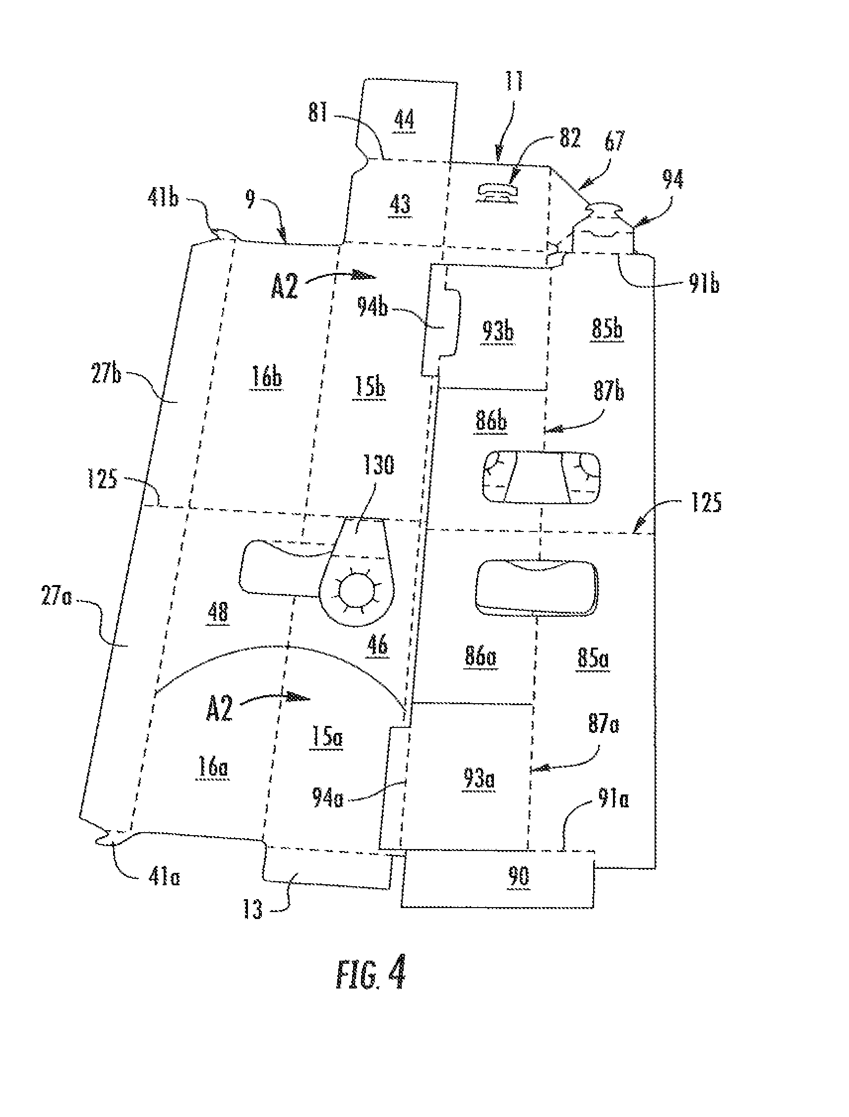
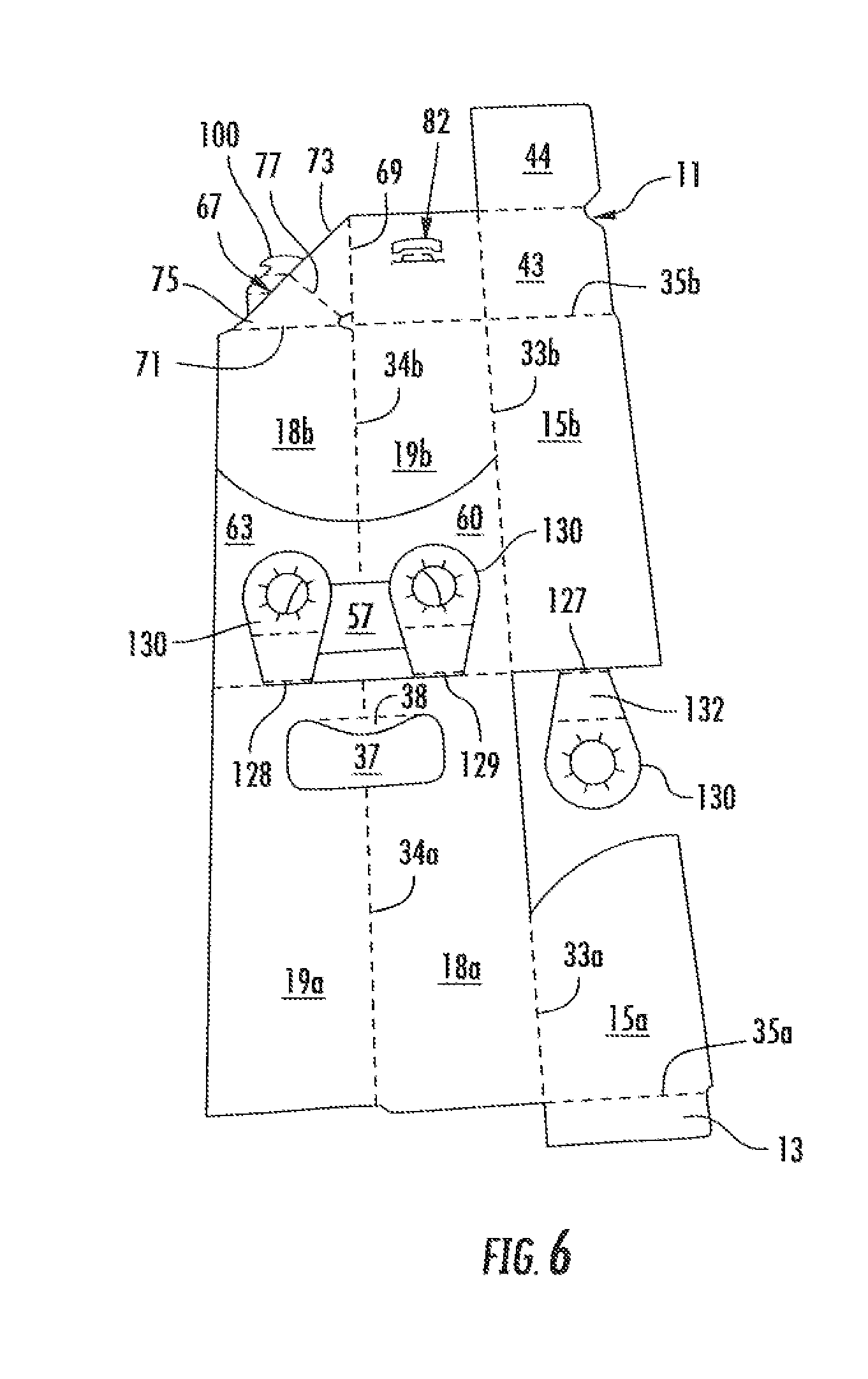
[0012] FIGS. 4-6 are views showing the folding of the carton blank to form a partially-erected carrier according to one embodiment of the disclosure. -9 illustrate the method of erecting the blank in FIG. 2
[0013] FIGS. 7 and 8 are views showing further folding of the partially-erected carrier of FIG. 6 into the carrier according to one embodiment of the disclosure.
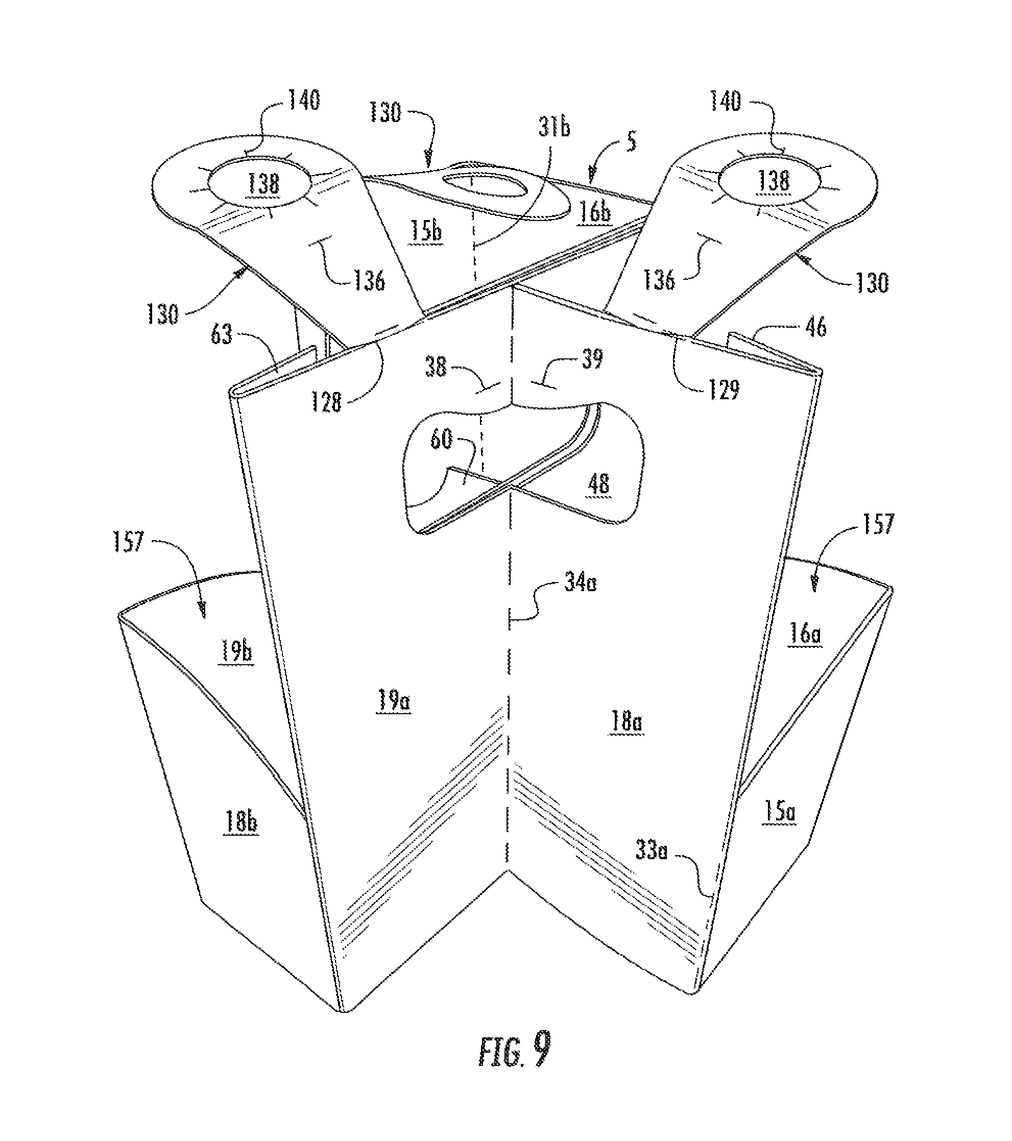
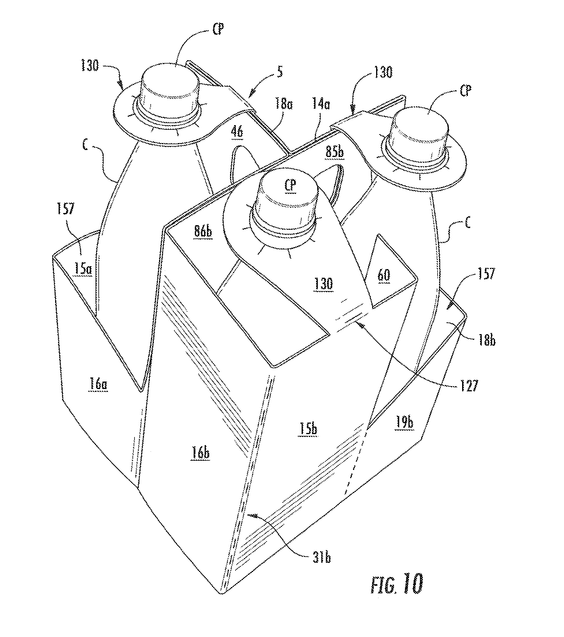
[0014] FIGS. 9 and 10 are perspective views of the exemplary basket-style carrier according to one embodiment of the disclosure.
[0015] Corresponding parts are designated by corresponding reference numbers throughout the drawings.
DETAILED DESCRIPTION OF THE EXEMPLARY EMBODIMENT
[0016] The present disclosure generally relates to carriers, packages, constructs, sleeves, cartons, or the like, for holding and displaying containers such as jars, bottles, cans, etc. The containers can be used for packaging food and beverage products, for example. The containers can be made from materials suitable in composition for packaging the particular food or beverage item, and the materials include, but are not limited to, plastics such as PET, LDPE, LLDPE, HDPE, PP, PS, PVC, EVOH, and Nylon; and the like; aluminum and/or other metals; glass; or any combination thereof.
[0017] Carriers according to the present disclosure can accommodate containers of numerous different shapes. For the purpose of illustration and not for the purpose of limiting the scope of the disclosure, the following detailed description describes beverage containers (e.g., glass bottles or plastic containers) at least partially disposed within the carrier embodiments. In this specification, the terms "lower," "bottom," "upper," "top," "front," and "back" indicate orientations determined in relation to fully erected carriers.
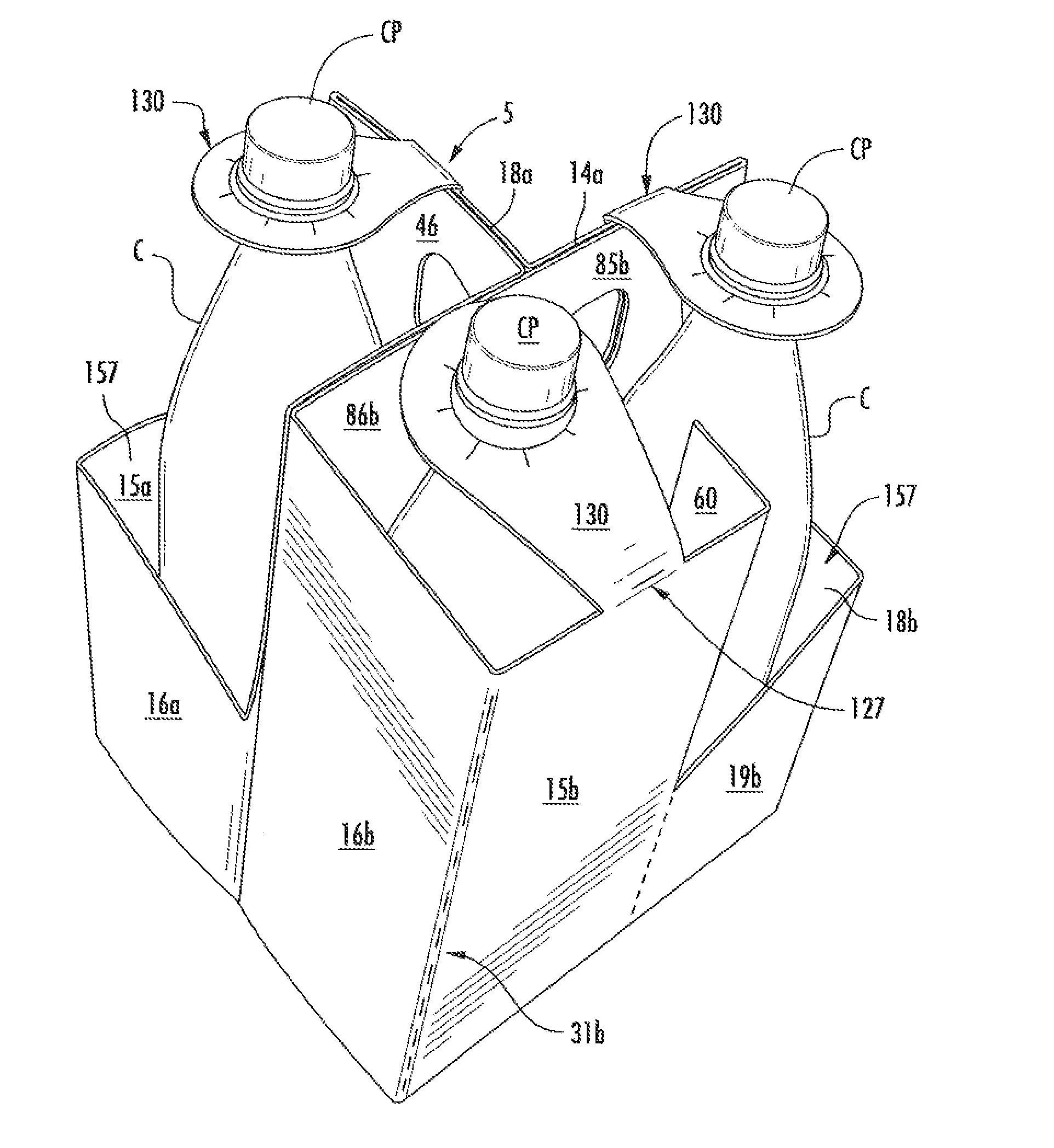
[0018] FIG. 1 is a plan view of an exterior side 1 of a blank 3 used to form a package or basket-style carrier 5 (FIG. 10), in accordance with an exemplary embodiment of the present disclosure. As shown in FIGS. 9 and 10, the carrier 5 is sized to contain three containers C, one containers being contained in a front portion of the carrier and two containers being contained in a back portion of the carrier. The carrier may be sized and shaped to hold more or less than three containers.
[0019] The blank 3 has a longitudinal axis L1 and a lateral axis L2. The blank 3 has a front portion 7, a back portion 9, a bottom panel 11 foldably connected to the back portion, and a bottom adhesive flap 13 foldably connected to the front portion. In the illustrated embodiment, the front portion 7 and back portion 9 are for being folded about a longitudinal centerline CL when the blank 3 is formed into the carrier 5. As discussed in more detail below, the blank 3 is formed into the carrier 5 by folding the blank about the centerline CL so that the front portion 7 and the back portion 9 are overlapped.
[0020] In the illustrated embodiment, the front portion 7, comprises a first front panel 15a foldably connected to a first side panel 16a and a second side panel 18a. The second side panel 18a is foldably connected to a second front panel 19a. The front portion 7 includes a first handle 21 located in the first front panel 15a and first side panel 16a. The first handle 21 includes a handle opening 22 and a handle flap 25 foldably connected to the first front panel 15a and first side panel 16a at a longitudinal fold line 26. The front portion 7 includes a second handle 36 located at least partially in the second front panel 19a and second side panel 18a. The second handle 36 includes a handle opening 37 and a handle flap 38 foldably connected to the second front panel 19a and second side panel 18a at a longitudinal fold line 39. A central panel flap 27a is foldably connected to the first side panel 16a at a lateral fold line 29a. A hook portion 41a is foldably connected to the central panel at a longitudinal fold line 42a. Lateral fold lines 31a, 33a, foldably connect respective first and second side panels 16a, 18a to first front panel 15a. Lateral fold line 34a foldably connects second side panel 18a to the second front panel 19a. A longitudinal fold line 35a connects the bottom panel adhesive flap 13 to the first front panel 15a.
[0021] In one embodiment, the front portion 7 comprises an arcuate cut line 45a that extends across the first front panel 15a and first side panel 16a and terminates at lateral fold lines 33a and 29a. The arcuate cut line 45a divides the first front panel 15a into an upper portion 46 and a lower portion 47; and first side panel 16a into an upper portion 48 and a lower portion 49. The arcuate cut line 45a may be arranged or shaped differently, such as substantially straight or angled without departing from the disclosure.
[0022] In the illustrated embodiment, the back portion 9, comprises a first back panel 15b foldably connected to a third side panel 16b and a second back panel 19a. The second back panel 19b is foldably connected to a fourth side panel 18b. The back portion 9 includes a handle 55 located in the second back panel 19b and fourth side panel 18a. The handle 55 includes a handle opening 57. A central panel flap 27b is foldably connected to the third side panel 16b at a lateral fold line 29b. Lateral fold lines 31b, 33b foldably connect respective first side panel 16b and second back panel 19b to first back panel 15b. Lateral fold line 34b foldably connects fourth side panel 18b to the second back panel 19b. A longitudinal fold line 35b connects the bottom panel 11 to the first and second back panels 15b, 19b.
[0023] In one embodiment, the back portion 9 comprises an arcuate cut line 45b that extends at least partially across the second back panel 19b and fourth side panel 18b and terminates at lateral fold lines 33b and 84b. The arcuate cut line 45b divides the second back panel 19b into an upper portion 60 and a lower portion 61; and second side panel 18b into an upper portion 63 and a lower portion 64. The arcuate cut line 45b may be arranged, shaped differently, such as substantially straight or angled without departing from the disclosure.
[0024] In one embodiment, the bottom panel 11 may have a first portion 43 foldably connected to a second portion 44 at a longitudinal fold line 81. The first portion 43 may have female locking features 82 configured to accept male locking features and hold the carrier together when the carrier is formed from the blank. The bottom panel 11 may also have a notch 65 for receiving the hooks 41a, 41b. A gusset 67 is formed in the blank 3 and foldably connected to the first portion 43 of the bottom panel 11 at lateral fold line 69 and to the fourth side panel 18b at a longitudinal fold line 71. The gusset 67 comprises a first gusset panel 73 foldably connected to a second gusset panel 75 at an oblique fold line 77. An aperture 79 may be located at the inside corner of the gusset 67 adjacent the first portion 43 of the bottom panel 11 and the fourth side panel 18b without departing from the disclosure.
[0025] In one embodiment, the front portion 7 includes a front central panel 83a foldably connected to the second front panel 19a at a lateral fold line 84a. The front central panel 83a has a first portion 85a foldably connected to a second portion 86a at a lateral fold line 87a. The front central panel 83a includes a handle opening 89a located in the first and second portions 85a, 86a of the central panel 83a. A keel 90 is foldably connected to the first portion 85a of central panel 83a at a longitudinal fold line 91. A front divider flap 93a is foldably connected to the first portion 85a of the front central panel 83a at the lateral fold line 87a and is at least partially defined by an upper longitudinal cut 96a and a lower longitudinal cut 97a. An adhesive flap 94a is foldably connected to the front divider flap 93a at lateral fold line 95a.
[0026] The back portion 9 includes a back central panel 83b foldably connected to the fourth side panel 18b at a lateral fold line 84b. The back central panel 83b has a first portion 85b foldably connected to a second portion 86b at a lateral fold line 87b. The back central panel 83b includes a handle opening 89b located in the first and second portions 85b, 86b of the central panel 83b. An attachment flap 99 is foldably connected to the first portion 85b of central panel 83b at a longitudinal fold line 91b. As illustrated in FIG. 1, the attachment flap 99 has male locking features 100 that are configured to mate with the female locking features located in first portion 43 of the bottom panel 11 and hold the carrier 5 together when the carrier is formed from the blank 3. A back divider flap 93b is foldably connected to the first portion 85b of the back central panel 83b at the lateral fold line 87b and at least partially defined by an upper cut 96b and a lateral edge of the blank 3. An adhesive flap 94b is foldably connected to the back divider flap 93b at lateral fold lines 95b and partially defined by cuts 102.
[0027] In the illustrated embodiment, the blank 3 includes a longitudinal fold line 125 that foldably connects the front central panel 83a and the back central panel 83b. and the central panel flap 27a to the back central panel flap 27b. The longitudinal fold line 125 is aligned with the longitudinal centerline CL of the blank 3.
[0028] As shown in FIG. 2, the front portion 7 has a tamper resistant retention flap 130 foldably connected to the first back panel 15b at fold line 127. The retention flap 130 has a first portion 132 foldably connected to a second portion 134 at a longitudinal fold line 136. The first portion 132 may have trapezoidal, isosceles trapezoid, square, or any other shape without departing from the disclosure. The second portion 134 may have a generally curved shape and an aperture 138 with cuts 140 that are circumferentially located around and extend radially outward from the center of the aperture 138 The cuts 140 define tab portions 142 and the aperture 138 is generally sized to securely hold the neck portion of a container C, for example, as shown in FIG. 10. The tab portions 142 flex or bend providing clearance for the cap portion CP of the container C to pass there through. The tab portions 142 provide container removal resistance and indicated if someone or something has been tampering with the container. The retention flap 130 is defined by cut line 144 in the upper portion 46 of the first front panel 15a and may extend at least partially into the handle 21. The retention flap may be alternatively shaped or arranged without departing from the disclosure.
[0029] In one embodiment, the second side panel 18b and second back panel 19b each have a tamper resistant retention flap 130 as described above defined therein. The retention flap 130 of the second side panel 18b is foldably connected to the second front panel 19a at fold line 128. The retention flap 130 of the second back panel 19b is foldably connected to the second side panel 18a at fold line 129.
[0030] Any of the panels, flaps, fold lines, cuts, or other features could be otherwise shaped, arranged, and/or omitted from the blank 3 without departing from the disclosure. The blank 3 could be sized and/or shaped to accommodate more or less than three containers without departing from this disclosure.
[0031] With reference to FIGS. 3-10, in one exemplary method of erection, the blank 3 is positioned with its exterior surface 1 facing down, as illustrated in FIG. 3. The carrier 5 may be erected from the blank 3 by respectively folding the central panels 83a, 83b in the direction of arrows A1 about fold lines 84a, 84b so that the central panels are in face-to-face relationship with portions the front and back panels 15a, 15b. Glue or other adhesive is selectively applied to the blank 3 to adhesively connect the adhesive flap 94a to the front panel 15a and to adhesively connect the adhesive flap 94b to the back panel 15b. Next, the keel 90 is folded about fold line 91 to be in face-to-face contact with the exterior surface 1 of the central panel 83a. Next, the upper portions 46 and 48 are pushed inward and the first side panels 16a, 16b are folded in the direction of arrows A2 (FIG. 4) about fold lines 31a, 31b so that the first side panels are in face-to-face contact with portions of the front and back panels 15a, 15b. As the side panels 16a, 16b are being folded the upper portions 46 and 48 of the first front panel 15a and first side panel 16a are inserted in between and adhesively secured to the second portion 86a of the central panel 83a and the second side panel 18a. As illustrated in FIG. 5, portions of the central panels 27a, 27b are in face-to-face contact with portions of the second portions 86a, 86b of the central panels 83a, 83b and the central panels 27a, 27b can be selectively adhesively secured thereto with glue. Upper portions 60 and 63 of the second back panel 19b and second side panel 18b may be adhesively secured with glue to the back central panel 83b.
[0032] Next, the partially assembled blank 3 is folded in the direction of arrow A3 (FIG. 7) about the longitudinal centerline CL so that the front portion 7 overlaps the back portion 9 and glue may be applied generally where indicated by "g" in FIG. 1 to the front and back central panels 83a 83b. The bottom panel 11 is attached to the bottom panel adhesive flap 13 by glue or by mechanical means. As shown in FIG. 9, the blank 3 is further assembled into the carrier by positioning the first side panels 16a, 16b and second side panels 18a, 18b to be in a generally spaced-apart, parallel planar relationship and positioning the front panel 15a and back panel 15b to be in a generally spaced-apart, parallel planar relationship. Such movement of the side panels 16a, 16b, 18a, 18b and front and back panels 15a, 15b, causes the divider flap 93a in the front portion of the carrier 5 to be positioned generally perpendicular to the central panel 83a. Accordingly, the divider flap 93b in the back portion of the carrier 5 to be positioned generally perpendicular to the central panel 83b and the back portion of the carrier is divided into two container receiving spaces 157 by the divider flap 93b. The first front panel 15a, first side panel 16a, and the front divider flap 93a form the first container-receiving space. The first back panel 15b, third side panel 16b, and the back divider flap 93b form the second container-receiving space. The second back panel 19b, fourth side panel 18b, and the back divider flap 93b form the third container-receiving space. The hooks 41a, 41b are also positioned into the notch 65 in the bottom panel to prevent the carrier from returning to its original configuration. Next the male locking features 100 of the attachment flap 99 are locked into place within the female locking features in the first portion 43 of the bottom panel 11.
[0033] Containers can be placed into the container receiving spaces 157 of the carrier 5. The bottoms of the containers are supported by the first and second portions 43, 44 of the bottom panel 11 of the carrier 5. The apertures 138 of the tamper resistant retention flaps 130 are aligned with the containers C and the retention flaps 130 are then pushed down into place past the cap CP to the neck of the containers C. The retention flaps 130 are attached to containers C to stabilize the containers in the spaces 157 of the carrier 5 and to provide indication that the containers have been removed from the carrier. If the carrier 5 has been tampered (i.e., the containers removed and then replaced) the retention flap 130 will be torn or damaged to provide visual indication of tampering. As shown in FIGS. 9 and 10, the container-receiving spaces 157 in the front portion and the back portion of the carrier 5 are substantially open along a top edge (e.g., an uppermost edge) of the carrier 5. As shown in FIG. 10, the container-receiving spaces 157 remain substantially open when the retention flaps 130 engage the containers C. Further, as shown in FIGS. 9 and 10, the retention flaps 130 are foldably connected to respective top edges (e.g., uppermost edges) of the respective first back panel 15b, second side panel 18a, and second front panel 19a along respective fold lines 127, 129, 128.
[0034] The exemplary carrier embodiment discussed above accommodates three containers arranged in two rows, but the present disclosure is not limited to these numbers. As one example, additional containers may be accommodated by increasing the size of the blank 3 (e.g., in the longitudinal direction L1 in FIG. 1) and forming additional container-receiving spaces therein. Also, the blank 3 could have less than three container-receiving spaces.
[0035] In general, the blank may be constructed from paperboard having a caliper so that it is heavier and more rigid than ordinary paper. The blank can also be constructed of other materials, such as cardboard, or any other material having properties suitable for enabling the carton to function at least generally as described above. The blank can be coated with, for example, a clay coating. The clay coating may then be printed over with product, advertising, and other information or images. The blanks may then be coated with a varnish to protect information printed on the blanks. The blanks may also be coated with, for example, a moisture barrier layer, on either or both sides of the blanks. The blanks can also be laminated to or coated with one or more sheet-like materials at selected panels or panel sections.
[0036] As an example, a tear line can include: a slit that extends partially into the material along the desired line of weakness, and/or a series of spaced apart slits that extend partially into and/or completely through the material along the desired line of weakness, or various combinations of these features. As a more specific example, one type tear line is in the form of a series of spaced apart slits that extend completely through the material, with adjacent slits being spaced apart slightly so that a nick (e.g., a small somewhat bridging-like piece of the material) is defined between the adjacent slits for typically temporarily connecting the material across the tear line. The nicks are broken during tearing along the tear line. The nicks typically are a relatively small percentage of the tear line, and alternatively the nicks can be omitted from or torn in a tear line such that the tear line is a continuous cut line. That is, it is within the scope of the present disclosure for each of the tear lines to be replaced with a continuous slit, or the like. For example, a cut line can be a continuous slit or could be wider than a slit without departing from the present disclosure.
[0037] In accordance with the exemplary embodiments, a fold line can be any substantially linear, although not necessarily straight, form of weakening that facilitates folding therealong. More specifically, but not for the purpose of narrowing the scope of the present disclosure, fold lines include: a score line, such as lines formed with a blunt scoring knife, or the like, which creates a crushed or depressed portion in the material along the desired line of weakness; a cut that extends partially into a material along the desired line of weakness, and/or a series of cuts that extend partially into and/or completely through the material along the desired line of weakness; and various combinations of these features. In situations where cutting is used to create a fold line, typically the cutting will not be overly extensive in a manner that might cause a reasonable user to incorrectly consider the fold line to be a tear line.
[0038] The above embodiments may be described as having one or more panels adhered together by glue during erection of the carton embodiments. The term "glue" is intended to encompass all manner of adhesives commonly used to secure carton panels in place.
[0039] The foregoing description of the disclosure illustrates and describes various exemplary embodiments. Various additions, modifications, changes, etc., could be made to the exemplary embodiments without departing from the spirit and scope of the disclosure. It is intended that all matter contained in the above description or shown in the accompanying drawings shall be interpreted as illustrative and not in a limiting sense. Additionally, the disclosure shows and describes only selected embodiments of the disclosure, but the disclosure is capable of use in various other combinations, modifications, and environments and is capable of changes or modifications within the scope of the inventive concept as expressed herein, commensurate with the above teachings, and/or within the skill or knowledge of the relevant art. Furthermore, certain features and characteristics of each embodiment may be selectively interchanged and applied to other illustrated and non-illustrated embodiments of the disclosure.
* * * * *
D00000
D00001
D00002
D00003
D00004
D00005
D00006
D00007
D00008
D00009
D00010
P00999
XML
uspto.report is an independent third-party trademark research tool that is not affiliated, endorsed, or sponsored by the United States Patent and Trademark Office (USPTO) or any other governmental organization. The information provided by uspto.report is based on publicly available data at the time of writing and is intended for informational purposes only.
While we strive to provide accurate and up-to-date information, we do not guarantee the accuracy, completeness, reliability, or suitability of the information displayed on this site. The use of this site is at your own risk. Any reliance you place on such information is therefore strictly at your own risk.
All official trademark data, including owner information, should be verified by visiting the official USPTO website at www.uspto.gov. This site is not intended to replace professional legal advice and should not be used as a substitute for consulting with a legal professional who is knowledgeable about trademark law.