Sleeving Machine Hopper
BRADLEY; Michael
U.S. patent application number 15/880292 was filed with the patent office on 2019-07-25 for sleeving machine hopper. The applicant listed for this patent is Keymac USA LLC. Invention is credited to Michael BRADLEY.
| Application Number | 20190225358 15/880292 |
| Document ID | / |
| Family ID | 67299705 |
| Filed Date | 2019-07-25 |


| United States Patent Application | 20190225358 |
| Kind Code | A1 |
| BRADLEY; Michael | July 25, 2019 |
SLEEVING MACHINE HOPPER
Abstract
A packaging machine hopper is provided for holding a stack of packaging articles with each article in a generally horizontal orientation. The hopper comprises a support for holding at least part of the stack at an angle to vertical.
| Inventors: | BRADLEY; Michael; (Bristol, GB) | ||||||||||
| Applicant: |
|
||||||||||
|---|---|---|---|---|---|---|---|---|---|---|---|
| Family ID: | 67299705 | ||||||||||
| Appl. No.: | 15/880292 | ||||||||||
| Filed: | January 25, 2018 |
| Current U.S. Class: | 1/1 |
| Current CPC Class: | B65B 35/16 20130101; B65H 1/22 20130101; B65H 2801/81 20130101; B65B 19/105 20130101; B65H 1/06 20130101; B65H 2405/311 20130101; B65B 43/145 20130101; B65H 1/04 20130101; B65H 2405/15 20130101; B65H 2701/1764 20130101; B65H 1/225 20130101; B65H 2405/1142 20130101 |
| International Class: | B65B 35/16 20060101 B65B035/16; B65H 1/22 20060101 B65H001/22; B65H 1/04 20060101 B65H001/04; B65B 19/10 20060101 B65B019/10 |
Claims
1. A packaging machine hopper for holding a stack of packaging articles, the hopper comprising a support for holding at least part of the stack at an angle to vertical.
2. A hopper as claimed in claim 1, in which each article is held in a generally horizontal orientation in use.
3. A hopper as claimed in claim 1, in which the hopper support holds at least part of the stack at an angle in the range 40 degrees to 50 degrees.
4. A hopper as claimed in claim 1, in which the hopper support holds at least part of the stack at approximately 45 degrees.
5. A hopper as claimed in claim 1, in which the hopper support includes an inclined section and generally vertical terminal section.
6. A hopper as claimed in claim 5, in which the vertical terminal section is provided by spacer elements.
7. A hopper as claimed in claim 5, in which the vertical terminal section is provided by a cranked support section.
8. A hopper as claimed in claim 1, in which the support comprises a plurality of hopper rods defining a channel for receiving sleeves.
9. A hopper as claimed in claim 8, in which the rods are generally straight.
10. A hopper as claimed in claim 8, in which the hopper rods include an inclined portion and terminal cranked portion.
11. A hopper as claimed in claim 1, in which the hopper comprises a removable support plate and the support is carried on or by the plate.
12. A hopper as claimed in claim 1, in which the support includes a guide bar.
13. A hopper as claimed in claim 1, comprising a low level alert.
14. A packaging machine having a hopper as claimed in claim 1.
15. A machine as claimed in claim 14, in which the hopper is filled with a plurality of cartons or sleeves.
16. A machine as claimed in claim 14, in which the cartons or sleeves are oriented so as to be generally horizontal and generally flat in the hopper.
17. A sleeving machine hopper arrangement, the arrangement being formed as a change part which is securable and removable from a sleeving machine, the arrangement comprising a support plate, a plurality of hopper rods are carried on or by said support plate, each of said hopper rods including a major rod portion which is inclined with respect to said plate, each of said rods further comprising a terminal crank portion, said terminal crank portions extending generally orthogonally to said plate.
18. A hopper arrangement as claimed in claim 17, in which the support plate includes a main plate portion which is securable to a sleeving machine, and a minor plate portion, said minor plate portion being sunken with respect to the major plate portion, said hopper rods being carried on or by said minor plate portion.
19. An arrangement as claimed in claim 17, further comprising one or more guide bars, said bar being secured to a hopper rod and extending generally parallel to the major rod portion.
20. A hopper rod having a major rod portion and a terminal crank portion, said major rod portion being an elongate rod, said crank portion extending from one end of said major rod portion, said crank portion being angled with respect to said major rod portion.
Description
[0001] The present invention relates generally to a machine for automatically placing a packaging article, such as a sleeve or carton, around a pack.
[0002] There are many circumstances in which a final product is placed in a sleeve; for example food packs such as trays, cartons and the like. Machines for automating the process of placing the product in the sleeve (or the sleeve around the product) are known.
[0003] An aspect of the present invention provides a packaging machine hopper for holding a stack of packaging articles (for example with each article in a generally horizontal orientation), the hopper comprising a support for holding at least part of the stack at an angle to vertical.
[0004] The hopper support may hold at least part of the stack at an angle in the range 40 degrees to 50 degrees; for example the hopper support may holds at least part of the stack at approximately 45 degrees.
[0005] In some embodiments the hopper support includes an inclined section and generally vertical terminal section.
[0006] The support may comprise a plurality of hopper rods, bars or the like defining a channel for receiving sleeves.
[0007] The hopper rods may include an inclined portion and terminal cranked portion.
[0008] The hopper may comprise a removable support plate, with the support carried on or by the plate.
[0009] A low-level alert function may be provided.
[0010] The present invention also provides a packaging machine having a hopper as described herein. The hopper may be filled with a plurality of cartons or sleeves.
[0011] The present invention also provides a sleeving machine having a hopper as described herein.
[0012] Some aspects and embodiments of the invention are configured for use with a 4, 5 or 6 panel packaging sleeve. In some embodiments the sleeves are generally flat or planar.
[0013] The present invention also provides a machine as described herein, in which the hopper is filled with a plurality of cartons or sleeves.
[0014] The cartons or sleeves may be oriented so as to be generally horizontal and generally flat in the hopper.
[0015] The present invention also provides a sleeving machine hopper arrangement, the arrangement being formed as a change part which is securable and removable from a sleeving machine, the arrangement comprising a support plate, a plurality of hopper rods are carried on or by said support plate, each of said hopper rods including a major rod portion which is inclined with respect to said plate, each of said rods further comprising a terminal crank portion, said terminal crank portions extending generally orthogonally to said plate.
[0016] The support plate may include a main plate portion which is securable to a sleeving machine, and a minor plate portion, said minor plate portion being sunken with respect to the major plate portion, said hopper rods being carried on or by said minor plate portion.
[0017] The arrangement may further comprise one or more guide bars, said bar being secured to a hopper rod and extending generally parallel to the major rod portion.
[0018] The present invention also provides a hopper rod having a major rod portion and a terminal crank portion, said major rod portion being an elongate rod, said crank portion extending from one end of said major rod portion, said crank portion being angled with respect to said major rod portion.
[0019] Different aspects and embodiments of the invention may be used separately or together.
[0020] Further particular and preferred aspects of the present invention are set out in the accompanying independent and dependent claims. Features of the dependent claims may be combined with the features of the independent claims as appropriate, and in combinations other than those explicitly set out in the claims.
[0021] The present invention will now be more particularly described, by way of example, with reference to the accompanying drawings, in which.
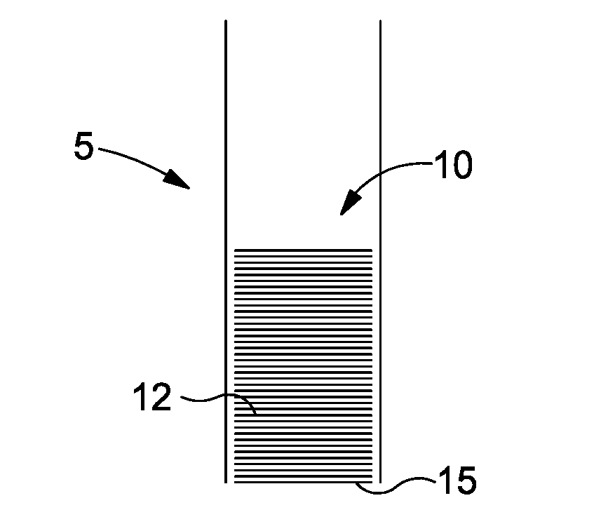
[0022] FIG. 1 illustrates a known hopper arrangement;
[0023] FIG. 2 illustrates a principle of a hopper formed according to an embodiment of the present invention;
[0024] FIG. 3 shows a hopper formed according to a further embodiment of the present invention;
[0025] FIG. 4 shows a rear side perspective view of a hopper arrangement formed according to a further embodiment of the present invention;
[0026] FIG. 5 shows a front side perspective view of the hopper arrangement of FIG. 4;
[0027] FIG. 6 shows a further rear side perspective view of the hopper arrangement of FIG. 4;
[0028] FIG. 7 shows part of a sleeving machine fitted with the hopper arrangement of FIG. 4;
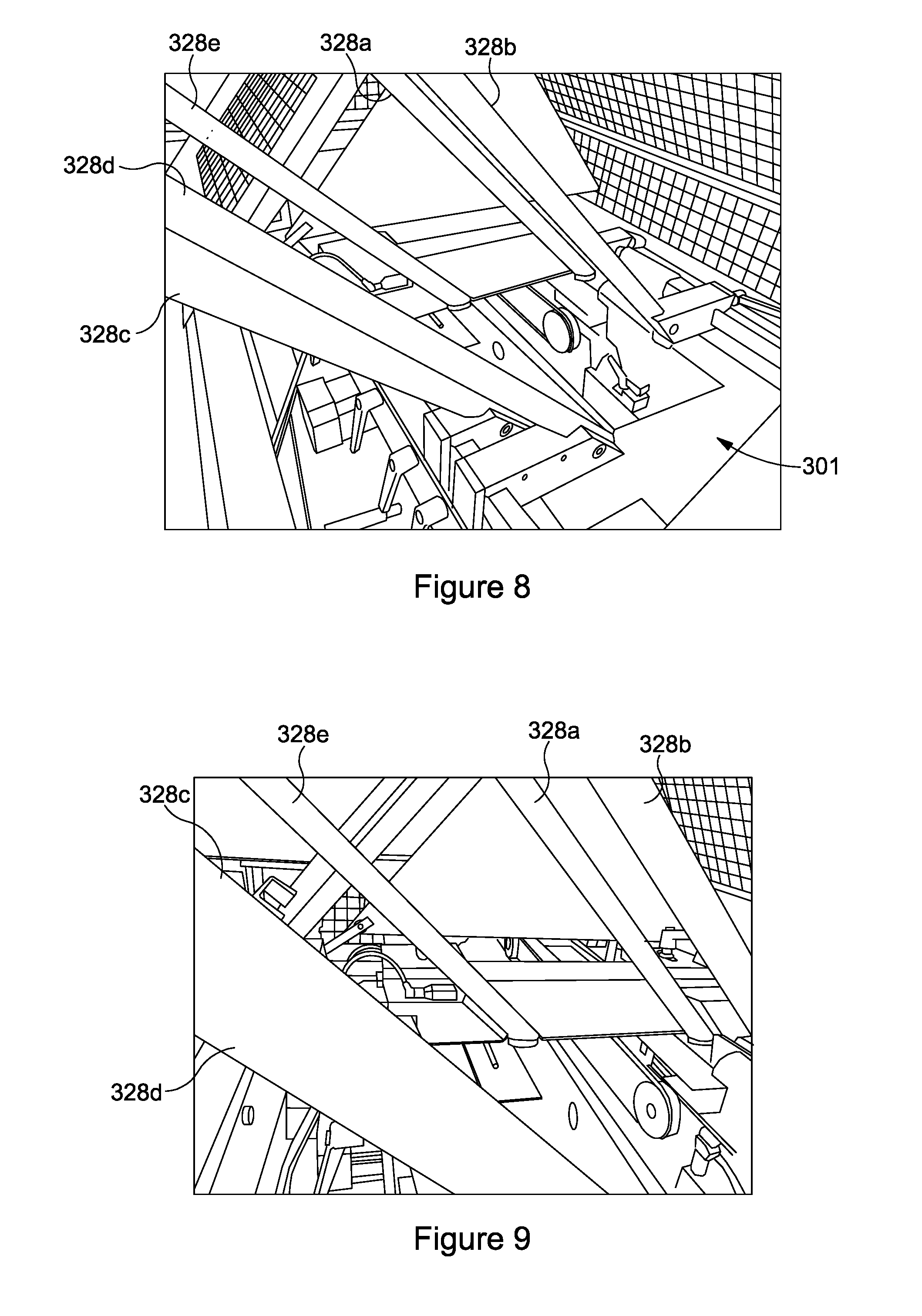
[0029] FIG. 8 shows a sleeving machine fitted with a hopper arrangement formed in accordance with a further embodiment;
[0030] FIG. 9 shows a further view of the hopper arrangement of FIG. 8; and
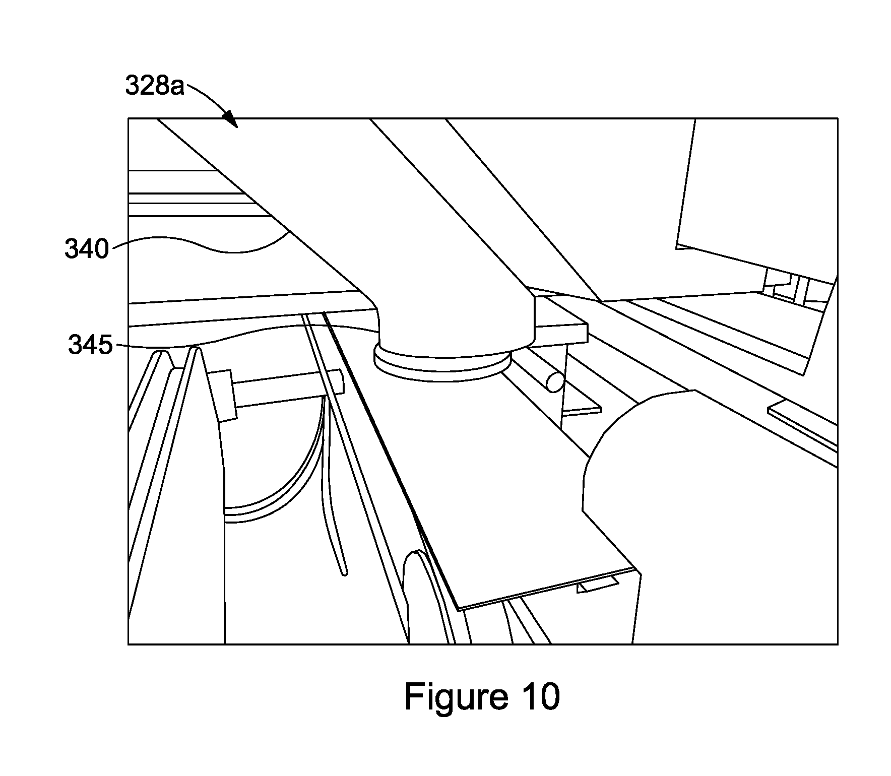
[0031] FIG. 10 is a magnified view of the hopper arrangement of FIG. 8.
[0032] The example embodiments are described in sufficient detail to enable those of ordinary skill in the art to embody and implement the systems and processes herein described. It is important to understand that embodiments can be provided in many alternate forms and should not be construed as limited to the examples set forth herein.
[0033] Accordingly, while embodiment can be modified in various ways and take on various alternative forms, specific embodiments thereof are shown in the drawings and described in detail below as examples. There is no intent to limit to the particular forms disclosed. On the contrary, all modifications, equivalents, and alternatives falling within the scope of the appended claims should be included. Elements of the example embodiments are consistently denoted by the same reference numerals throughout the drawings and detailed description where appropriate.
[0034] Unless otherwise defined, all terms (including technical and scientific terms) used herein are to be interpreted as is customary in the art. It will be further understood that terms in common usage should also be interpreted as is customary in the relevant art and not in an idealized or overly formal sense unless expressly so defined herein.
[0035] In the following description, all orientational terms, such as upper, lower, radially and axially, are used in relation to the drawings and should not be interpreted as limiting on the invention.
[0036] Vertical hoppers 5 (see FIG. 1) are known for holding a stack 10 of sleeves 12. These hoppers are prone to allowing sleeves/cartons to fall through because of the weight and high pressure on the front sleeve or carton 15 and the direction in which gravity works.
[0037] Referring to FIG. 2, the principle of the hopper 25 of the present invention eliminates that pressure by offsetting the stack 20 (e.g. leaning it "backwards") on a 45-degree angle. Because the weight on the front sleeve 27 is reduced (because the load is taken by the hopper) there is a reduced chance of a double feed. In addition, the sleeves are "shingled" i.e. they are laterally offset from each other, which helps to separate them and ensure that only one sleeve is fed at a time from the terminal end of the hopper. Leaning the support backwards has also been found to improve access in use.
[0038] In FIG. 3 the hopper 125 includes an inclined section 130 and a vertical terminal section 135. This means that the majority of the stack 120 leans (providing the pressure elimination and separating benefits) but the final few (for example 10 mm) of the stack is vertical, making it easier for the final sleeve 127 to be picked.
[0039] In use a stack of sleeves (for example flat, pre-glued sleeves) is loaded into the hopper from the "top". An associated packaging machine can then take sleeves from the "bottom" of the stack i.e. the first sleeve in the stack.
[0040] In the embodiment of FIGS. 4 to 7 the hopper 225 includes a hopper support comprising a series of inclined straight rods: a single, central rear rod 228a; a pair of side rods 228b, 228c, and a pair of front rods 228d, 228e. A guide bar 229 is also connected to the rod 228d.
[0041] The hopper 225 includes a plate 224a which carries the rods. The plate 224a is removably secured to the machine by a nut 224b, and is removable from the rest of the machine so that the hopper can be removed and easily replaced with a different hopper (e.g. for different types of sleeves).
[0042] In this embodiment a short section of sleeves at the bottom of the stack 220 are substantially vertical. This is achieved by providing a spacer block 260 at the base of each bar, which effectively provide a cranked lower/terminal portion (although in this embodiment the spacer block is formed as a separate component). This is a key feature to keeping the front sleeve 227 in registration and stops sideways movement when feeding.
[0043] The orientation of the carton/sleeve hopper 225 also allows better access from the side of the machine for sleeve loading.
[0044] The hopper 225 also keeps the sleeve in the same orientation through the entire sleeving operation without needing to rotate it through angles as it would be with a rotary feeder.
[0045] FIGS. 8 to 10 show a hopper 325 formed according to a further embodiment. The hopper 325 comprises five supports rods 328a-e arranged and configured to form a channel for receiving a stack of sleeves, cartons or the like for feeding into a packaging machine 301. As shown best in FIG. 10, each of the bars includes an inclined section 340 and a terminal, vertical section 345 with a cranked section giving an elbow like terminal portion. In other words, in this embodiment the rod is a single piece, with the cranked terminal portion formed integrally with the inclined section.
[0046] Although illustrative embodiments of the invention have been disclosed in detail herein, with reference to the accompanying drawings, it is understood that the invention is not limited to the precise embodiments shown and that various changes and modifications can be effected therein by one skilled in the art without departing from the scope of the invention.
* * * * *
D00000
D00001
D00002
D00003
D00004
D00005
XML
uspto.report is an independent third-party trademark research tool that is not affiliated, endorsed, or sponsored by the United States Patent and Trademark Office (USPTO) or any other governmental organization. The information provided by uspto.report is based on publicly available data at the time of writing and is intended for informational purposes only.
While we strive to provide accurate and up-to-date information, we do not guarantee the accuracy, completeness, reliability, or suitability of the information displayed on this site. The use of this site is at your own risk. Any reliance you place on such information is therefore strictly at your own risk.
All official trademark data, including owner information, should be verified by visiting the official USPTO website at www.uspto.gov. This site is not intended to replace professional legal advice and should not be used as a substitute for consulting with a legal professional who is knowledgeable about trademark law.