Locking Hydraulic Side Swim Platform
Lapierre; Gary ; et al.
U.S. patent application number 15/875673 was filed with the patent office on 2019-07-25 for locking hydraulic side swim platform. This patent application is currently assigned to GENERAL HYDRAULIC SOLUTIONS, INC.. The applicant listed for this patent is GENERAL HYDRAULIC SOLUTIONS, INC.. Invention is credited to Kevin Cureton, Gary Lapierre.
| Application Number | 20190225305 15/875673 |
| Document ID | / |
| Family ID | 67299719 |
| Filed Date | 2019-07-25 |


| United States Patent Application | 20190225305 |
| Kind Code | A1 |
| Lapierre; Gary ; et al. | July 25, 2019 |
Locking Hydraulic Side Swim Platform
Abstract
A swim platform is built into a side of a boat, either the port or starboard side. The swim platform is raised and lowered by a mechanism that fits within the side wall of the boat beneath the gunnel. The swim platform is raised when the boat is underway to prevent water intrusion, provide safety, and reduce drag; while the swim platform is lowered, for example, when the boat is anchored for enjoyment of the boaters using the boat.
| Inventors: | Lapierre; Gary; (Clearwater, FL) ; Cureton; Kevin; (Clearwater, FL) | ||||||||||
| Applicant: |
|
||||||||||
|---|---|---|---|---|---|---|---|---|---|---|---|
| Assignee: | GENERAL HYDRAULIC SOLUTIONS,
INC. Clearwater FL |
||||||||||
| Family ID: | 67299719 | ||||||||||
| Appl. No.: | 15/875673 | ||||||||||
| Filed: | January 19, 2018 |
| Current U.S. Class: | 1/1 |
| Current CPC Class: | B63B 27/14 20130101; B63B 27/146 20130101; B63B 19/08 20130101; B63B 2029/022 20130101; B63B 2003/485 20130101; B63B 3/48 20130101 |
| International Class: | B63B 27/14 20060101 B63B027/14; B63B 3/48 20060101 B63B003/48 |
Claims
1. A side swim platform system comprising: a side swim platform sized to fit within an opening in a side wall of a boat, the opening having a first side and second, opposing side; a first shaft mechanically fixed to a first side edge of the side swim platform and a second shaft mechanically fixed to a second, opposite side edge of the side swim platform; a first hydraulic ram mounted within a boat side wall at the first side of the opening, a first end of the first hydraulic ram rotatably interfaced to a first bearing, the first bearing affixed to an inside surface of the side wall of the boat, a second, opposing end of the first hydraulic ram interfaced directly to the first shaft through a first monolithic linkage, the first monolithic linkage converting linear motion from the first hydraulic ram directly into a rotational motion of the first shaft causing the first shaft to rotate; and a second hydraulic ram mounted within the boat side wall at the second, opposing side of the opening, a first end of the second hydraulic ram rotatably interfaced to a second bearing, the second bearing affixed to a second inside surface of the side wall of the boat, a second, opposing end of the second hydraulic ram interfaced directly to the second shaft through a second monolithic linkage, the second monolithic linkage converting the linear motion from the second hydraulic ram directly into the rotational motion of the second shaft; whereas extension of the first hydraulic ram and extension of the second hydraulic ram in tandem retracts the side swim platform and retraction of the first hydraulic ram and retraction of the second hydraulic ram in tandem extends the side swim platform.
2. The side swim platform system of claim 1, further comprising a locking mechanism, the locking mechanism having an open position in which the side swim platform is movable by extension or retraction of the first hydraulic ram and the second hydraulic ram and a locked position in which the side swim platform is locked in a fully retracted position.
3. The side swim platform system of claim 1, whereas in a fully retracted position, an outer surface of the side swim platform is flush with an outer surface of the side wall of the boat.
4. The side swim platform system of claim 2, wherein the locking mechanism comprises a retractable pin, the retractable pin movable into a retracted position in which the retractable pin is positioned within the first side of the opening in the side wall of the boat and movable into an extended position in which the retractable pin extends out of the first side edge and into a receiver, the receiver located in the first side edge of the side swim platform.
5. The side swim platform system of claim 4, wherein the locking mechanism further comprises a second retractable pin, the second retractable pin movable into the retracted position in which the retractable pin is positioned within the second side of the opening in the side wall of the boat and movable into the extended position in which the retractable pin extends out of the second side of the opening in the side edge and into a second receiver, the second receiver located in the second side edge of the side swim platform.
6. The side swim platform system of claim 4, wherein the retractable pin is moved by a hydraulic actuator.
7. The side swim platform system of claim 5, wherein the second retractable pin is moved by a hydraulic actuator.
8. The side swim platform system of claim 1, wherein the first linkage comprises a first monolithic knuckle bearing linkage and the second linkage comprises a second monolithic knuckle bearing linkage.
9. The side swim platform system of claim 1, wherein the first side of the opening includes a first platform plate, the second, opposing side of the opening includes a second platform plate, the first side edge of the side swim platform includes a first side wall plate, and the second, opposite side edge of the side swim platform includes a second side wall plate.
10. The side swim platform system of claim 9, wherein the first platform plate, the second platform plate, the first side wall plate, and the second side wall plate are fabricated from steel.
11. A method of deploying a side swim platform from a boat comprising: operating a hydraulic ram to retract the hydraulic ram, the hydraulic ram thereby pulling on a monolithic knuckle linkage thereby rotating a shaft in a first rotational direction, the shaft affixed to the side swim platform and, therefore, the side swim platform extending outwardly from the boat.
12. The method of claim 11, further comprising the step of: operating the hydraulic ram to extend the hydraulic ram, the hydraulic ram thereby pushing on the monolithic knuckle linkage thereby rotating the shaft in a second, opposing direction of rotation, and, therefore, the side swim platform retracting inwardly.
13. The method of claim 12, further comprising after the step of the swim platform retracting inwardly, the step of: locking the swim platform in line with a side of the boat by extending a hydraulically operated pin between the side of the boat and the side swim platform.
14. The method of claim 12, further comprising the step of: operating a second hydraulic ram to retract the hydraulic ram, the second hydraulic ram thereby pulling on a second monolithic knuckle linkage thereby rotating a second pivot in the first rotational direction, the second shaft affixed to an opposite side of the side swim platform and, therefore, the side swim platform extending outwardly from the boat.
15. A mechanism for moving a side swim platform between a retracted position and an extended position, the mechanism comprising: a shaft pivot mechanically affixed to a first side edge of a side swim platform and extending into a side wall of the boat, the side swim platform sized to fit within an opening in the side wall of a boat; and a hydraulic ram mounted within the side wall of the boat at the first side of the opening, a first end of the hydraulic ram rotatably interfaced to a bearing, the bearing affixed to the boat, a second, opposing end of the hydraulic ram interfaced to the shaft through a linkage, the linkage converting linear motion from the hydraulic ram into a rotational motion of the pivot; whereas extension of the hydraulic ram rotates the shaft in a first direction of rotation and retraction of the hydraulic ram rotates the shaft in a second direction of rotational.
16. The mechanism for moving the side swim platform between the retracted position and the extended position of claim 15, further comprising a locking mechanism, the locking mechanism having an open position have a locking pin retracted therein and a locked position having the locking pin extended therefrom.
17. The mechanism for moving the side swim platform between the retracted position and the extended position of claim 15, wherein the linkage comprises a first knuckle bearing linkage.
Description
FIELD
[0001] This invention relates to the field of boating and more particularly to a system for raising and lowering of a side swim platform of a pleasure craft.
BACKGROUND
[0002] Many existing boats have swim platforms at the stern of the boat. These swim platforms are usually fixed in place and provide an area for people to stand, sit, sunbathe, etc. Basically, the swim platform is much like an extension to the deck of the boat.
[0003] There also exists swim platforms that raise and lower to allow for a payload (e.g. a kayak, a jet ski) to be lowered into the water and, later, raised out of the water.
[0004] Such swim platforms that raise and lower, do not enclose the deck area of the boat and typically remain approximately horizontal (e.g. they do not raise into a vertical position).
[0005] Swim platforms are very prevalent in inboard and I/O boats because the engine is within the hull of the boat. Swim platforms are less prevalent or non-existent in boats that have one or more outboard engines, as the outboard engine precludes mounting of a swim platform to the stern of the boat.
[0006] Recently, various boats, in particular, center-console fishing boats include a side door for entering/exiting from a dock. Such doors are manually operable, open inwardly, and do not provide increased deck space for access when swimming and diving.
[0007] Still, there is a need or desire for a swim platform for boats that have outboard engines.
[0008] What is needed is a system that will raise and lower a side-mounted swim platform.
SUMMARY
[0009] A swim platform is built into a side of a boat, either the port or starboard side of the boat. The swim platform is raised and lowered by a mechanism that fits within the side wall of the boat beneath the gunnel. The swim platform is raised when the boat is underway to prevent water intrusion, provide safety, and reduce drag; while the swim platform is lowered when the boat is anchored for enjoyment of the boaters using the boat.
[0010] In one embodiment, a side swim platform system is disclosed including a swim platform sized to fit within an opening in a side of a boat; the opening has a first side and second, opposing side. A first pivot is mechanically fixed to a first side edge of the swim platform and a second pivot is mechanically fixed to a second, opposite side edge of the swim platform. A first hydraulic ram is mounted within a boat side wall at the first side of the opening, a first end of which is interfaced to a first bearing, the first bearing being affixed to a first side edge of the opening. A second, opposing end of the first hydraulic ram is interfaced to the first pivot through a first linkage that converts linear motion from the first hydraulic ram into a rotational motion of the first pivot. A second hydraulic ram is mounted within the boat side wall at the second, opposing side of the opening. aA first end of the second hydraulic ram is interfaced to a second bearing that is affixed to a second side edge of the opening. A second, opposing end of the second hydraulic ram is interfaced to the second pivot through a second linkage that converts the linear motion from the second hydraulic ram into the rotational motion of the second pivot. Extension of the first hydraulic ram and extension of the second hydraulic ram in tandem retracts the swim platform and retraction of the first hydraulic ram and retraction of the second hydraulic ram in tandem extends the swim platform.
[0011] In another embodiment, a method of deploying a side swim platform from a boat is disclosed including operating a hydraulic ram to retract the hydraulic ram, the hydraulic ram thereby pulling on a knuckle linkage thereby rotating a pivot in a first rotational direction, the pivot affixed to a side swim platform and, therefore, the side swim platform extending outwardly from the boat.
[0012] In another embodiment, a mechanism for moving a side swim platform between a retracted position and an extended position is disclosed including a pivot mechanically affixed to a first side edge of a swim platform, the swim platform sized to fit within an opening in a side of a boat. A hydraulic ram mounted within a boat side wall at the first side of the opening. A first end of the hydraulic ram interfaced to a bearing allowing rotation, the bearing affixed to a first side edge of the opening. A second, opposing end of the hydraulic ram interfaced to the pivot through a linkage, the linkage converting linear motion from the hydraulic ram into a rotational motion of the pivot. Upon extension of the hydraulic ram, the pivot rotates in a first direction of rotation for moving the swim platform to the extended position and retraction of the hydraulic ram rotates the pivot in a second direction of rotational for moving the swim platform to the retracted position.
BRIEF DESCRIPTION OF THE DRAWINGS
[0013] The invention can be best understood by those having ordinary skill in the art by reference to the following detailed description when considered in conjunction with the accompanying drawings in which:
[0014] FIG. 1 illustrates a schematic view of a side swim platform lift mechanism.
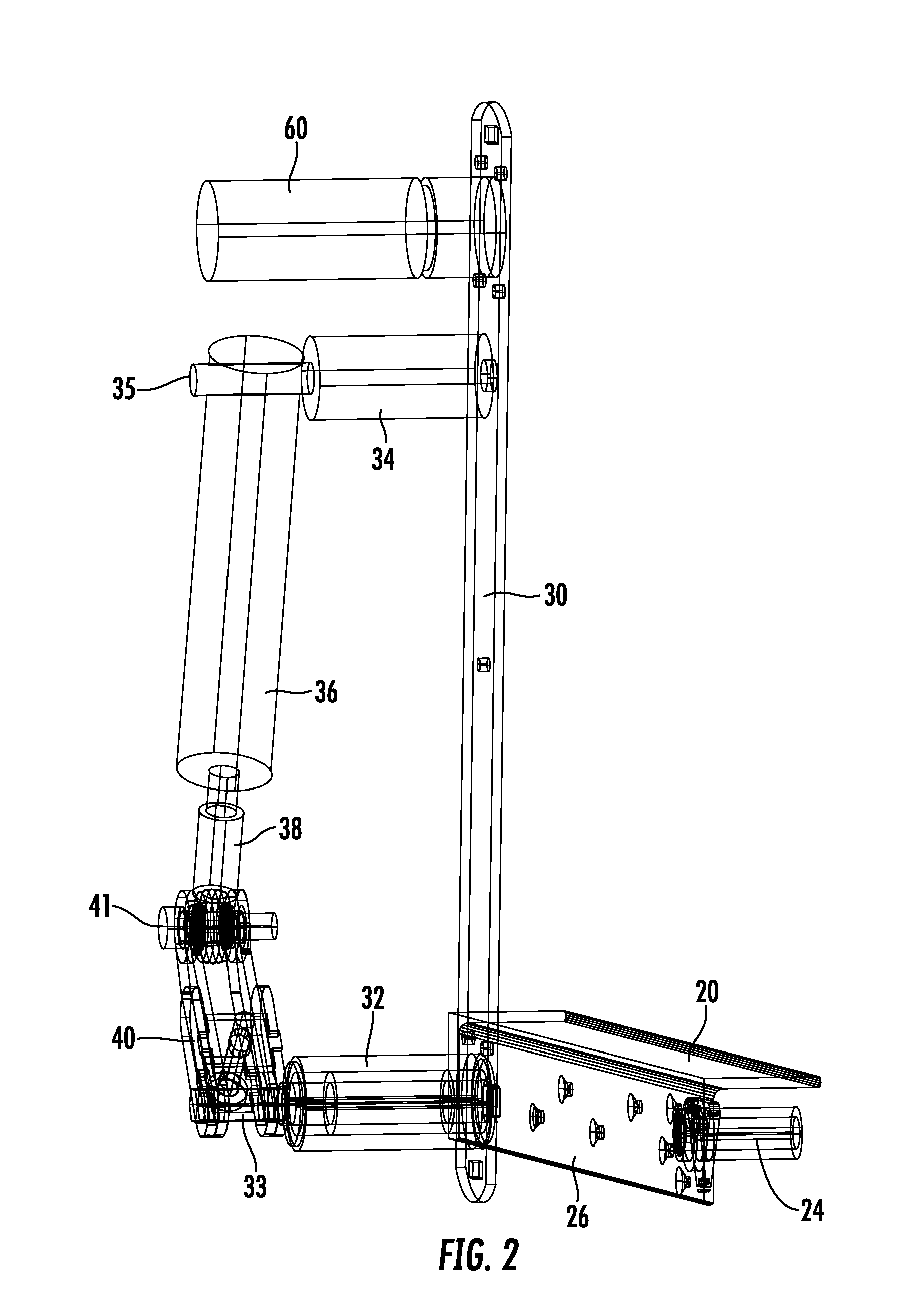
[0015] FIG. 2 illustrates a schematic view of the right-side of the side swim platform lift mechanism.
[0016] FIG. 3 illustrates a schematic view of the left-side of the side swim platform lift mechanism.
[0017] FIG. 4 illustrates a perspective view of the swim platform lift mechanism interfaced to a side swim platform.
[0018] FIG. 6 illustrates a perspective view of the hydraulic lock and hydraulic ram of the swim platform lift mechanism interfaced to the side swim platform.
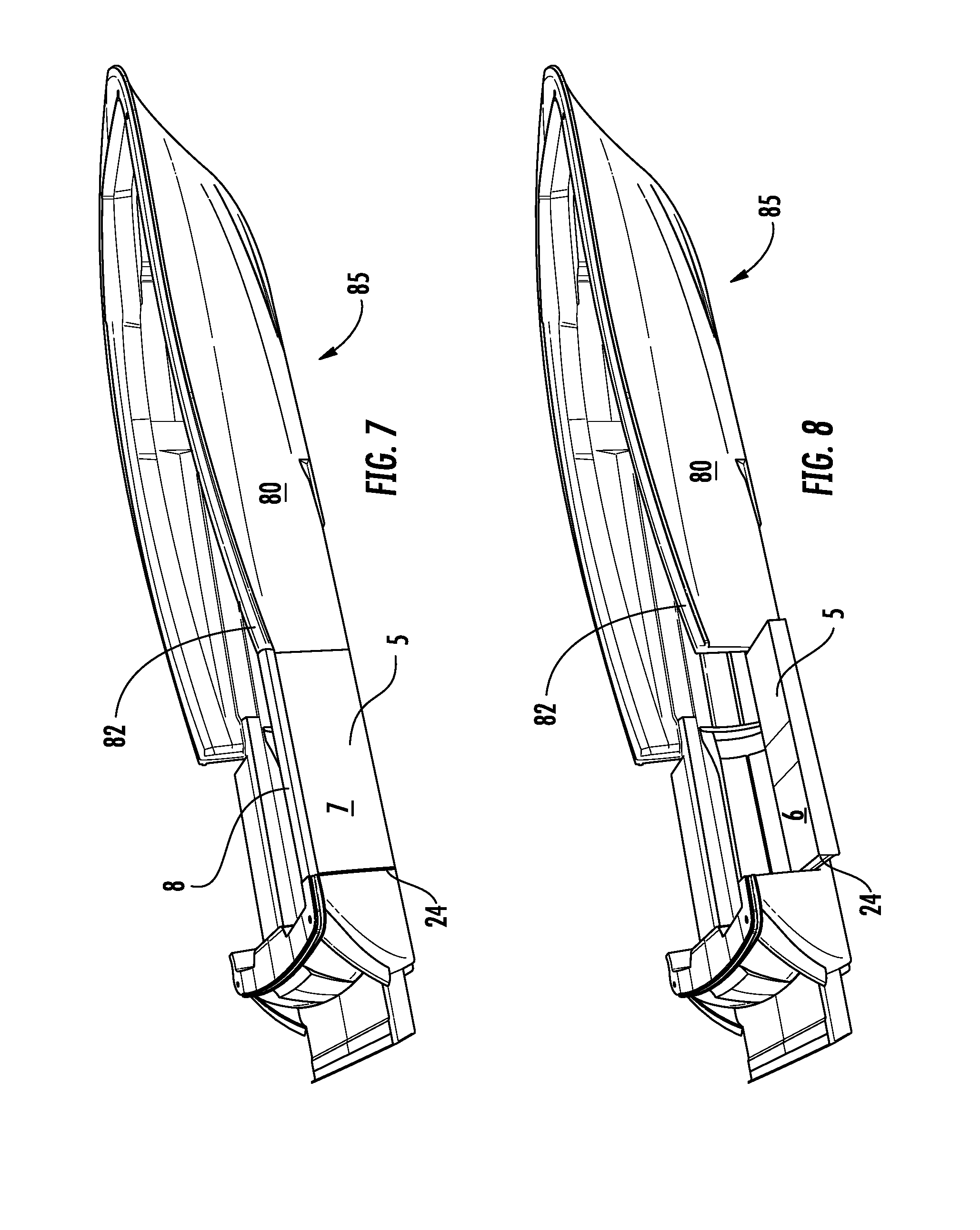
[0019] FIGS. 7 and 8 illustrates perspective views of a boat equipped with the swim platform lift mechanism and the side swim platform.
DETAILED DESCRIPTION
[0020] Reference will now be made in detail to the presently preferred embodiments of the invention, examples of which are illustrated in the accompanying drawings. Throughout the following detailed description, the same reference numerals refer to the same elements in all figures.
[0021] Referring to FIGS. 1-6, schematic views and perspective views of a side swim platform lift mechanism are shown. The side swim platform lift mechanism needs to fit within an opening in the side-wall 80 of a boat 85 (see FIG. 7). The side-wall 80 of the typical boat 5 has limited space beneath the gunnel 82 and the side swim platform lift mechanism needs to move the side swim platform 5 (see FIGS. 5-7) from a substantially horizontal position (deployed) to a substantially vertical position (retracted). The side swim platform 5 rests flush with the side-wall 82 of the boat 85 when retracted, thereby forming a continuation of the side-wall 82 of the boat, preferably matching the height of the gunnel 82.
[0022] In order to provide a compact deployment mechanism that is capable of raising and lowering the side swim platform 5, a compact hydraulic system is used. In this, within the side 80 (see FIG. 8) of the boat 85, on both sides of the side swim platform 5, a hydraulic ram 36 is interfaced to linkages 38/40/41 that provide rotational torque to a pivot 33 at a lower area of a side wall 24 (see FIG. 8) of the side swim platform 5 such that, an extending actuation of the hydraulic ram 36 rotates the pivot 33 to extend the side swim platform 5 and a retracting actuation of the hydraulic ram 36 rotates the pivot 33 to retract/raise the side swim platform 5. In a preferred embodiment, once the side swim platform 5 is raised and sealed to become a side wall of the boat 85, a lock such as a hydraulic lock 60 is actuated to 1414.3 6 lock the side swim platform 5 against the sides of the opening in the side wall 80 of the boat 5.
[0023] The mechanisms of FIGS. 1-6 accomplish the raising and lowering of the side swim platform 5 through a mechanism that is shown as an example and is in no way limiting as substitution of various components and component sizes are known in the industry.
[0024] The side swim platform 5 is made by cutting/forming an opening in the side wall 80 of a boat 85 and cutting/forming a side swim platform 5 that fits within this opening. The opening has substantially flat sides and a substantially flat floor. In a preferred embodiment, the substantially flat floor is flush with a deck of the boat 85 and, for safety, is preferably textured in the same way as the deck of the boat 85.
[0025] For added strength, in some embodiments, a side-wall plate 30 is mounted to the inside or outside surface of the sides of the opening. A lock 60 is mounted at the top inside surface of the sides of the opening and a lock pin 31 slideably interfaces with a lock pin receiver 25 at a corresponding top side surface of the side swim platform 5. In some embodiments, the lock 60 is a hydraulic lock, though any form of lock is anticipated including a solenoid lock or a manual lock (e.g. spring-loaded lock, manual release).
[0026] For added strength, in some embodiments, the inside or outside side surfaces of the side swim platform 5 includes a platform plate 20.
[0027] The deployment mechanism is preferably symmetrical on each side of the opening. For deployment of the side swim platform 5, the side swim platform 5 rotates by way of rotating pivots 33 (one on each side of the opening) that is held in line with the side swim platform 5 by pivot bearings 32. The rotating pivots 33 pass from within the side of the opening, through the side of the opening, through the optional side-wall plate 30, and is fixed to the optional platform plate 20 and/or to a lower area of the side swim platform 5. Therefore, when the rotating pivot 33 rotates, the side swim platform 5 also rotates in the same direction, deploying or retracting the swim platform 5, depending upon a direction of rotation. The rotating pivot 33 on a first side of the opening rotates in one direction when the rotating pivot on the second, opposing side of the opening rotates in an opposite direction.
[0028] To provide sufficient torque to the rotating pivots 33 in order to deploy, and especially to retract a side swim platform 5 that is heavy in typical conditions experienced during boating, each rotating pivot 33 is linked to a hydraulic ram 36 through linkage 38/40/41 that converts the linear extension/retraction of the hydraulic ram 36 into the required rotational movement of the rotating pivots 33. A first end of the hydraulic ram 36 is interfaced to an inside surface of the side-wall plate 30 (or inside of the side-wall 82 at the opening) by a ram bearing 34/35. This allows the base portion of the hydraulic ram 36 to pivot and change angle with respect to the linkage 38/40/41. A distal, second end of the hydraulic ram 36 is linked to the rotating pivots 33 by a knuckle 40 that at one end is fixed to the rotating pivot 33 and at an opposing distal end is hingedly interfaced to the extension arm 38 of the hydraulic ram 33 by a hinge 41. This linkage 38/40/41 converts the high-force linear motion of the hydraulic ram 36 into the high-torque rotational motion of the rotating pivots 33. In some embodiments, the knuckle 40 is formed as part of the rotating pivot 33 while in some embodiments, the knuckle 40 is fixed to the rotating pivot 33 by any way known in the industry, for example, a knurled-interface, keyed-interface, non-round interface, etc.
[0029] Referring to FIGS. 7 and 8, perspective views of a boat 85 equipped with the swim platform lift mechanism and the side swim platform 5 are shown. In FIG. 7, the side swim platform 5 is shown in the retracted position, the outside surface 7 flush with the side 82 of the boat 85 while in FIG. 8, the side swim platform 5 is shown in the extended position, the inside surface 6 available for swimmers, etc. Note that in some embodiments, when the side swim platform 5 is in the extended position, the inside surface 6 of the side swim platform 5 is flush with a deck surface of the boat 85.
[0030] Note that, for safety and aesthetics, it is preferred that when the side swim platform 5 is in the retracted position, an upper edge 8 of the side swim platform is substantially flush with the gunnel 82 of the boat 85.
[0031] Note the side wall 24 of the side swim platform 5 to which the pivot 33 is affixed.
[0032] Equivalent elements can be substituted for the ones set forth above such that they perform in substantially the same manner in substantially the same way for achieving substantially the same result.
[0033] It is believed that the system and method as described and many of its attendant advantages will be understood by the foregoing description. It is also believed that it will be apparent that various changes may be made in the form, construction and arrangement of the components thereof without departing from the scope and spirit of the invention or without sacrificing all of its material advantages. The form herein before described being merely exemplary and explanatory embodiment thereof. It is the intention of the following claims to encompass and include such changes.
* * * * *
D00000
D00001
D00002
D00003
D00004
D00005
D00006
XML
uspto.report is an independent third-party trademark research tool that is not affiliated, endorsed, or sponsored by the United States Patent and Trademark Office (USPTO) or any other governmental organization. The information provided by uspto.report is based on publicly available data at the time of writing and is intended for informational purposes only.
While we strive to provide accurate and up-to-date information, we do not guarantee the accuracy, completeness, reliability, or suitability of the information displayed on this site. The use of this site is at your own risk. Any reliance you place on such information is therefore strictly at your own risk.
All official trademark data, including owner information, should be verified by visiting the official USPTO website at www.uspto.gov. This site is not intended to replace professional legal advice and should not be used as a substitute for consulting with a legal professional who is knowledgeable about trademark law.