Vehicle Seat
GUMPRECHT; Michael ; et al.
U.S. patent application number 16/254664 was filed with the patent office on 2019-07-25 for vehicle seat. The applicant listed for this patent is FAURECIA AUTOSITZE GMBH. Invention is credited to Michael GUMPRECHT, Bernd ROMER.
| Application Number | 20190225177 16/254664 |
| Document ID | / |
| Family ID | 67144777 |
| Filed Date | 2019-07-25 |

| United States Patent Application | 20190225177 |
| Kind Code | A1 |
| GUMPRECHT; Michael ; et al. | July 25, 2019 |
VEHICLE SEAT
Abstract
A vehicle seat includes a seat portion and a back rest coupled to the seat portion to extend upwardly away from the seat portion. The back rest includes a base frame coupled to the seat bottom to extend upwardly therefrom and a head frame coupled to the base frame to locate the base frame between the seat portion and the head frame. The vehicle seat further includes an airbag coupled to the back rest.
| Inventors: | GUMPRECHT; Michael; (Nassenfels, DE) ; ROMER; Bernd; (Stadthagen, DE) | ||||||||||
| Applicant: |
|
||||||||||
|---|---|---|---|---|---|---|---|---|---|---|---|
| Family ID: | 67144777 | ||||||||||
| Appl. No.: | 16/254664 | ||||||||||
| Filed: | January 23, 2019 |
| Current U.S. Class: | 1/1 |
| Current CPC Class: | B60R 21/23138 20130101; B60R 21/207 20130101; B60N 2/2222 20130101; B60N 2/838 20180201; B60R 2021/23146 20130101; B60N 2/22 20130101 |
| International Class: | B60R 21/207 20060101 B60R021/207; B60N 2/838 20060101 B60N002/838 |
Foreign Application Data
| Date | Code | Application Number |
|---|---|---|
| Jan 25, 2018 | DE | 10 2018 101 706.5 |
Claims
1. A vehicle seat comprising a back rest including a base frame and a head frame, the base frame being connected to a seating portion and the head frame being mounted via a pivot joint provided on each side of the vehicle seat to the base frame in such a way that it can be tilt adjusted, and an airbag module being built into the back rest, wherein the airbag module is connected to a beam which, together with the airbag module, bridges a joint formed as a result of the articulated connection of the head frame to the base frame, the beam being connected at its end region pivotably to the base frame and at its other end region pivotably and axially slidable to said head frame, in such a manner that the airbag module, being entrained by the beam, follows a tilt adjustment of the head frame.
2. The vehicle seat of claim 1, wherein the airbag module is designed as a single piece together with the beam.
3. The vehicle seat of claim 2, wherein the hinge is arranged at a front side of the backrest.
4. The vehicle seat of claim 2, wherein the hinge is arranged at a back side of the back rest.
5. The vehicle seat of claim 2, wherein the hinge is arranged between a front side and a back side of the backrest.
6. The vehicle seat of claim 1, wherein the hinge is arranged at a front side of the backrest.
7. The vehicle seat of claim 1, wherein the hinge is arranged at a back side of the back rest.
8. The vehicle seat of claim 1, wherein the hinge is arranged between a front side and a back side of the backrest.
9. A vehicle seat comprising a seat portion and a back rest comprising a base frame coupled to the seat portion to extend upwardly from the seat portion, a head frame coupled to the base frame to pivot about an axis, and a pivot joint configured to provide the axis and interconnect the head frame to the base frame, and an airbag module comprising a beam arranged to extend between and interconnect the head frame and the base frame and an airbag coupled to the beam to move therewith, wherein the beam is arranged to extend across the pivot joint and is coupled on a first end to the base frame to pivot about a lower axis and on a second end to the head frame to allow translation of the head frame relative to the beam.
10. The vehicle seat of claim 9, wherein the head frame pivots about an upper axis relative to the beam.
11. The vehicle seat of claim 10, wherein the upper axis translates relative to the base frame.
12. The vehicle seat of claim 9, wherein the beam is formed to include an elongated slot in the second end to allow for translating and pivoting movement of the head frame relative to the base frame.
13. The vehicle seat of claim 12, wherein the beam is formed to include a circular aperture in the first end.
Description
PRIORITY CLAIM
[0001] This application claims priority to German Application Serial No. DE102018101706.5, filed Jan. 25, 2018, which is expressly incorporated by reference herein.
BACKGROUND
[0002] The present disclosure relates to an occupant support, and particularly to an occupant support used in a vehicle. More particularly, the present disclosure relates to a vehicle seat including a backrest.
SUMMARY
[0003] According to the present disclosure, a vehicle seat includes a seat portion and a back rest coupled to the seat portion to extend upwardly away from the seat portion. The back rest includes a base frame coupled to the seat bottom to extend upwardly therefrom and a head frame coupled to the base frame to locate the base frame between the seat portion and the head frame.
[0004] In illustrative embodiments, the head frame is coupled to the base frame to tilt about an axis. The vehicle seat further comprises an airbag module arranged to extend between and interconnect the head frame and the base frame to cause airbag module to move with the head frame relative to the seat portion.
[0005] In illustrative embodiments, the airbag module includes a first end coupled to the base frame to pivot about a lower axis and an upper end coupled to the head frame to pivot and translate relative to the head frame.
[0006] In illustrative embodiments, the airbag module is formed to include a circular aperture on a first end and an elongate slot on an opposite second end. A first bolt coupled to the base frame in a fixed position relative to the base frame is arranged to extend into the circular aperture to provide the lower axis. A second bolt coupled to the head frame in a fixed position relative to the head frame is arranged to extend into the elongate slot to allow translational and pivotable movement of the head frame relative to the base frame.
[0007] Additional features of the present disclosure will become apparent to those skilled in the art upon consideration of illustrative embodiments exemplifying the best mode of carrying out the disclosure as presently perceived.
BRIEF DESCRIPTIONS OF THE DRAWINGS
[0008] The detailed description particularly refers to the accompanying figures in which:
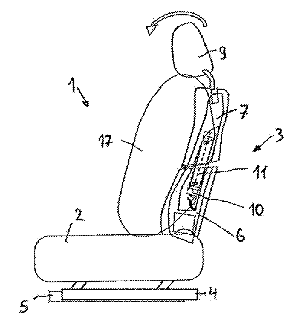
[0009] FIG. 1 is a schematic side view of a vehicle seat with a back rest in a default position and with deployed lateral airbag;
[0010] FIG. 2 is a representation according to FIG. 1 where the head frame of the back rest is adjusted to a forward position;
[0011] FIG. 3 is an exploded view of rest frame, beam, and airbag module;
[0012] FIG. 4 is a schematic representation of a joint between base frame and head frame in the default position according to FIG. 1;
[0013] FIG. 5 is a schematic representation similar to FIG. 4 with a head frame adjusted to a forward position according to FIG. 2; and
[0014] FIG. 6 is a set of schematic representations showing further options for the arrangement of a joint between head frame and base frame.
DETAILED DESCRIPTION
[0015] The drawing shown in the FIGS. 1 and 2 is a vehicle seat 1 having a seating portion 2 and a back rest 3 attached thereto. The vehicle seat 1 is mounted on a vehicle floor--not shown--in a way so that it can be longitudinally adjusted via pairs of rails provided on both sides, each comprising an upper rail 4 and lower rail 5. Hereby, the upper rails 4 are affixed to the seating portion 2 and the lower rails 5 to the vehicle floor.
[0016] The frame of the back rest 3 is split in two parts. It comprises a base frame 6 affixed to the seating portion 2 as well as a head frame 7 mounted on the base frame 6 in such a way that it can be adjusted in tilt. To that end, in the embodiment according to FIGS. 1-5, a hinge 8 is arranged between the base frame 6 and the head frame 7 at the front side of these. At its upper end the head frame 7 accommodates a head rest 9.
[0017] An airbag module 10 is built into the back rest 3 and connected firmly to a beam 11. In the built-in state the beam 11 and thereby also the airbag module 10 bridges a joint 12 formed due to the fact that the head frame 7 is coupled articulatedly with the base frame 6.
[0018] At its end associated with the base frame 6 the beam 11 is provided with a circular hole 13 and, at its end associated with the head frame 7, with an elongated hole 14, as can be seen from FIGS. 4 and 5. The hole 13 is penetrated by a stud bolt 15 firmly affixed to the base frame, and the elongated hole 14 is penetrated by a stud bolt 16 firmly affixed to the head frame. When the head frame 7 is adjusted the beam 11 rotates about the stud bolt 15 firmly affixed to the base frame thereby changing the distance between the stud bolt 15 firmly affixed to the base frame and the stud bolt 16 firmly affixed to the head frame. This change is compensated by shifting the stud bolt 16 firmly affixed to the head frame inside the elongated hole 14. This is shown in FIGS. 4 and 5 for a case where the head frame 7 has been adjusted forward whereby FIG. 4 shows the situation with the head frame 7 being in the default position and FIG. 5 the situation with the head frame 7 being adjusted forward to the maximum. This arrangement allows the beam 11 and thereby the airbag module 10 to follow the pivoting movement of the head frame 7 when the head frame 7 is adjusted relative to the base frame 6. Hereby, a deployed airbag 17 (see FIGS. 1 and 2) will have an associated position at any position the head frame 7 is adjusted to, where both the thorax region as well as the abdominal region of a seat occupant are protected by the airbag being in the associated position. In the schematic representations according to FIGS. 4 and 5 the airbag module 10 is not shown. The same applies to the FIG. 6.
[0019] In the above-described embodiment example, the beam 11 and the airbag module 10 are designed as separate components. In a further embodiment example, the beam 11 may be an integral component of the airbag module 10 thereby reducing the number of components.
[0020] In FIG. 6, alternatives for the arrangement of a hinge 8 between the base frame 6 and the head frame 7 are shown.
[0021] A vehicle seat 1 comprises a back rest 3 including a base frame 6 and a head frame 7. The base frame 6 is connected to a seating portion 2 and the head frame 7 is mounted, via a pivot joint 8 provided on each side of the seat, on the base frame 6 in such a way that its can be tilt adjusted, and an airbag module 10 built into the back rest 3. The airbag module 10 is connected to a beam 11 which, together with the airbag module 10, bridges a joint 12 formed as a result of the articulated connection of the head frame 7 to the base frame 6. The beam 11 is connected at its end region pivotably to the base frame 6 and at its other end region pivotably and axially slidable to the head frame 7, in such a manner that the airbag module 10, being entrained by the beam 11, follows a tilt adjustment of the head frame 7.
[0022] In one comparative example, a vehicle seat may comprise only one airbag device. Comparative vehicle seats having only one airbag device have the airbag device is mounted either on the head frame thereby protecting primarily the thorax region of the occupant or, alternatively, on the base frame so that the airbag device protects the abdominal region of the occupant. To protect both regions, an additional airbag device may be used.
[0023] In another comparative example, a vehicle seat may comprise an airbag device for protecting the head and a further airbag device for protecting the thorax region of a seat occupant. Both airbag devices are mounted on the head frame thereby following any adjustment movement when the head frame is adjusted. In this example, in the event of a crash, the two air cushions deploy in a matter to protect the head and the thorax region of the seat occupant regardless of the position the head frame is adjusted to.
[0024] A vehicle seat in accordance with the present disclosure provides desired protection of the thorax region and the abdominal region of a seat occupant at any position the head frame is adjusted to using only one airbag device mounted in the back rest. This is accomplished by providing a vehicle seat comprising the features of the claim 1.
[0025] In the vehicle seat according to the present disclosure, due to the fact that the head frame is articulatedly coupled with the base frame, there exists a joint between these two components. The airbag module is connected to a beam bridging this joint. By virtue of this, the airbag module is affixed both to the base frame as well as to the head frame. To that end, the end region of the beam is pivotably connected to the base frame and the other end region is connected pivotably and axially pivotably to the head frame. Based on this connection the beam and, together with it, the airbag module follows the movement when the angle of the head frame is adjusted. Consequently, a deployed airbag will have, at any position the head frame is adjusted to, a desired position in which both the thorax region and the abdominal region of a seat occupant are protected.
[0026] The beam and the airbag module may be designed as separate components. In a further development of the present disclosure it is provided, however, to design the beam as an integral component of the airbag module. This one-piece design reduces the number of components.
[0027] The hinge connecting the head frame and the base frame is arranged on the front side of the back rest. In further embodiments of the present disclosure, however, it may alternatively be arranged on the back side of the back rest or, respectively, between the front side and the back side of the back rest.
* * * * *
D00000
D00001
XML
uspto.report is an independent third-party trademark research tool that is not affiliated, endorsed, or sponsored by the United States Patent and Trademark Office (USPTO) or any other governmental organization. The information provided by uspto.report is based on publicly available data at the time of writing and is intended for informational purposes only.
While we strive to provide accurate and up-to-date information, we do not guarantee the accuracy, completeness, reliability, or suitability of the information displayed on this site. The use of this site is at your own risk. Any reliance you place on such information is therefore strictly at your own risk.
All official trademark data, including owner information, should be verified by visiting the official USPTO website at www.uspto.gov. This site is not intended to replace professional legal advice and should not be used as a substitute for consulting with a legal professional who is knowledgeable about trademark law.