Dynamic Compensation Of A Robot Arm Mounted On A Flexble Arm
Pivac; Mark
U.S. patent application number 16/317800 was filed with the patent office on 2019-07-25 for dynamic compensation of a robot arm mounted on a flexble arm. The applicant listed for this patent is FASTBRICK IP PTY LTD. Invention is credited to Mark Pivac.
| Application Number | 20190224846 16/317800 |
| Document ID | / |
| Family ID | 60951588 |
| Filed Date | 2019-07-25 |


| United States Patent Application | 20190224846 |
| Kind Code | A1 |
| Pivac; Mark | July 25, 2019 |
DYNAMIC COMPENSATION OF A ROBOT ARM MOUNTED ON A FLEXBLE ARM
Abstract
A control system is described for a base supporting a telescoping articulated boom assembly indicated generally at 15, comprising long telescopic boom 17 and telescopic stick 19. Mounted to the remote end 21 of the stick 19 is an end effector in the form of a head 23 that supports a 6 axis robot arm 25 that moves a further end effector 27 to manipulate the items. The robot arm 25 has a robot base 31, and mounted above the robot base 31 is a first target in the form of a 6 degree of freedom (6 DOF) high data rate position sensor 33, that provides 6 DOF position coordinates, relative to a fixed ground reference 35, to a control system. Mounted on the end of the robot arm 25 immediately above the end effector 27 is a second target in the form of a 6 degree of freedom (6 DOF) high data rate position sensor 37, that provides 6 DOF position coordinates, relative to the fixed ground reference 35, to the control system. The fixed ground reference 35 tracks the sensor 33 and feeds data to the control system to move the head with slow dynamic response within range of work for the robot arm, and tracks the sensor 37 to control movement of the robotic arm 25 and end effector 27 with fast dynamic response.
| Inventors: | Pivac; Mark; (Perth, WA) | ||||||||||
| Applicant: |
|
||||||||||
|---|---|---|---|---|---|---|---|---|---|---|---|
| Family ID: | 60951588 | ||||||||||
| Appl. No.: | 16/317800 | ||||||||||
| Filed: | July 17, 2017 | ||||||||||
| PCT Filed: | July 17, 2017 | ||||||||||
| PCT NO: | PCT/AU2017/050739 | ||||||||||
| 371 Date: | January 14, 2019 |
| Current U.S. Class: | 1/1 |
| Current CPC Class: | G05B 19/4097 20130101; B28D 1/186 20130101; E04G 21/22 20130101; E04F 21/023 20130101; G05B 2219/40257 20130101; G06F 2111/20 20200101; B28D 1/003 20130101; G01C 15/002 20130101; B28D 7/005 20130101; B60P 3/28 20130101; G05B 2219/45086 20130101; G05B 2219/39001 20130101; B25J 9/1651 20130101; B60P 1/48 20130101; B66C 13/22 20130101; B28D 1/10 20130101; B25J 9/023 20130101; B28D 7/04 20130101; B25J 19/022 20130101; G05B 2219/35207 20130101; B25J 9/1633 20130101; B25J 9/1635 20130101; G01S 17/66 20130101; B25J 5/00 20130101; G06F 16/1734 20190101; G06F 30/13 20200101; B25J 9/161 20130101; B25J 9/1694 20130101; B25J 9/1679 20130101; E04B 2/04 20130101; B25J 9/1664 20130101; B25J 19/021 20130101; G06F 16/00 20190101; B25J 9/1612 20130101; B25J 9/1674 20130101; B25J 9/1684 20130101; B25J 9/1697 20130101; G05B 19/416 20130101; B25J 9/162 20130101; B25J 9/1638 20130101; B25J 13/089 20130101 |
| International Class: | B25J 9/16 20060101 B25J009/16 |
Foreign Application Data
| Date | Code | Application Number |
|---|---|---|
| Jul 15, 2016 | AU | 2016902787 |
| Jul 14, 2017 | AU | PCT/AU2017/050731 |
Claims
1. A control system for a boom supported from a boom base, said boom having a robot arm mounted by a robot base therefrom, said robot arm having an end effector, said boom being moveable relative to said boom base by a boom controller interfaced with a boom actuator to position said robot base to a programmed location, said robot arm being movable by a robot arm controller interfaced with a robot arm actuator to position said end effector at a programmed position and orientation; said control system having a tracker system to track the position of a first target located by an offset proximal to said robot base, and to track the position and orientation of a second target located with a TCP offset from said end effector TCP; wherein said tracker system tracks the position of said first target and feeds data to said boom controller to operate said boom actuator with a slow dynamic response to dynamically position said first target close to said offset to position said robot base close to said programmed location, and said tracker system tracks the position and orientation of said second target and feeds data derived from said second target, or derived from said second target and said first target to said robot arm controller to operate said robot arm actuator with a fast dynamic response to dynamically position and orientate said end effector TCP to said programmed position and orientation.
2. A control system as claimed in claim 1 wherein said second target is located with said TCP offset from said end effector TCP so as to move with movement and pose of said end effector.
3. A control system as claimed in claim 1 or 2 wherein said robot base is mounted proximal to a remote end of said boom, away from said boom base.
4. A control system as claimed in any one of the preceding claims wherein said robot base and said first target is mounted on a head, mounted to the remote end of the boom.
5. A control system as claimed in any one of the preceding claims wherein said head is pivotally mounted to the remote end of the boom.
6. A control system as claimed in any one of the preceding claims wherein said head is pivotally mounted about a horizontal axis to the remote end of the boom.
7. A control system as claimed in any one of the preceding claims wherein said tracker system tracks the position and orientation of said first target, and feeds data to said boom controller to operate said boom actuator with a slow dynamic response to position and orientate said first target close to said offset to position said robot base close to said programmed location.
8. A control system as claimed in claim 6 or 7 wherein the poise of the head is controlled by a separate controller to the boom controller, and the boom controller operates the boom actuator to position the first target along three orthogonal axes.
9. A control system as claimed in claim 6 or 7 wherein control of the poise of the head is integrated into the boom controller, and the tracker system tracks the position and orientation of the first target.
10. A control system as claimed in any one of the preceding claims wherein said tracker system includes separate target tracking devices for said first target and said second target.
11. A control system as claimed in any one of the preceding claims wherein said robot arm controller may be controllably switched between a first state wherein said robot arm controller is responsive to positioning feedback data derived from said tracker system, to a second state where pre-calibrated positioning data referenced to the robot base (and hence the remote end of the boom) is relied on, and when switched between said first state and said second state, said robot arm controller controls movement of said robot arm to dampen movement of the robot arm, to avoid sudden movement of said robot arm and said end effector.
12. A control system as claimed in any one of the preceding claims wherein said boom base is provided with movement apparatus to move said boom base relative to the ground.
13. A control system as claimed in claim 12 wherein the movement apparatus is selected from a wheeled conveyance, incorporating locomotion or not, or self powered endless tracks.
14. A control system as claimed in claim 13 wherein the movement apparatus incorporates self levelling to level the boom base.
15. A control system as claimed in claim 12 or 13 wherein said boom base is mounted on an active suspension system, and said boom base incorporates a third target for said tracker system, said active suspension system having a suspension controller interfaced with a suspension actuator to control the position and orientation of said boom base in response to data from said tracker system reading the position and orientation of said third target.
16. A control system as claimed in claim 12 or 13 wherein said boom base is mounted to an object with an active suspension system, and said boom base incorporates a third target for said tracker system; said active suspension system having a suspension controller interfaced with a suspension actuator to control the position and orientation of said boom base relative to said object in response to data from said tracker system reading the position and orientation of said third target, said suspension actuator to control the position of said boom base.
Description
TECHNICAL FIELD
[0001] This invention relates to control of an end effector on a flexible arm, and in particular to the improved control of the position of the end effector on a flexible arm such as a boom. The invention has particular application where a robot works over a large area and requires high precision.
BACKGROUND ART
[0002] The following discussion of the background art is intended to facilitate an understanding of the present invention only. It should be appreciated that the discussion is not an acknowledgement or admission that any of the material referred to was part of the common general knowledge as at the priority date of the application.
[0003] The following definitions apply to terminology used throughout this patent specification. A robot arm is a programmable mechanical manipulator. In this specification a robot arm includes multi axis jointed arms, parallel kinematic robots (such as Stewart Platform, Delta robots), spherical geometry robots, Cartesian robots (orthogonal axis robots with linear motion) etc.
[0004] A boom is an elongate support structure such as a slewing boom, with or without stick or dipper, with or without telescopic elements, telescoping booms, telescoping articulated booms. Examples include crane booms, earthmover booms, truck crane booms, all with or without cable supported or cable braced elements. A boom may also include an overhead gantry structure, or cantilevered gantry, or a controlled tensile truss (the boom may not be a boom but a multi cable supported parallel kinematics crane (see PAR systems, Tensile Truss--Chernobyl Crane)), or other moveable arm that may translate position in space.
[0005] An end effector is the device at the end of a robotic arm designed to interact with the environment. An end effector may include a gripper, nozzle, sand blaster, spray gun, wrench, magnet, welding torch, cutting torch, saw, milling cutter, router cutter, hydraulic shears etc.
[0006] TCP is an abbreviation of tool centre point. This is the location on the end effector (or tool), whose position and orientation define the coordinates of the controlled object. It is typically located at the distal end of the kinematic chain. Kinematic chain refers to the chain of linkages and their joints between the base of a robot arm and the end effector.
[0007] CNC is an abbreviation for computer numerical control, used for automation of machines by computer/processor/microcontroller executed pre-programmed sequences of machine control commands.
[0008] The application of coordinate transformations within a CNC control system is usually performed to allow programming in a convenient coordinate system. It is also performed to allow correction of workpiece position errors when clamped in a vice or fixture on a CNC machining centre.
[0009] These coordinate transformations are usually applied in a static sense to account for static coordinate shifts or to correct static errors.
[0010] Robots and CNC machines are programmed in a convenient Cartesian coordinate system, and kinematic transformations are used to convert the Cartesian coordinates to joint positions to move the pose of the robot or CNC machine.
[0011] Measuring the position of a robot arm end effector close to the TCP in real time increases the accuracy of a robot. This is performed on static end effectors on robots used for probing and drilling. This is achieved by a multi-step process of moving to the programmed position, taking a position measurement, calculating a correction vector, adding the compensation vector to the programmed position and then moving the TCP to the new position. This process is not done in hard real time and relies on a static robot arm pose.
[0012] WO 2007/076581 describes a control system that moves a boom and end effector to a desired location or along a desired path. The boom was located on a base, which was in used fixed to the ground. A robot arm having a base was fixed to the end of the boom. A scanner-target measuring system measured the actual position and orientation of a target located on the end of the boom. The measuring system measured the actual position and orientation of the target with six degrees of freedom (x,y,z axes, and pitch, roll, and yaw) hereafter "6 DOF". The target located on the end of the boom is fixed relative to the base of the robotic arm. The control system then calculated a 6 DOF offset between the programmed position of the base of the robot arm (where it was expected to be) and the actual measured position of the base of the robot arm, and then applied a correction to the kinematic chain of the robot arm so that the end effector was translated to the correct position. The robot arm was programmed in a coordinate system relative to its base, not the ground. Thus, to program the TCP of the end effector it was necessary to transform its 6 DOF position in ground coordinates to the base coordinates of the robot arm mounted on the tip of the boom. Effectively what was done was to program the robot arm with a sub program that was always used to control the end effector to lay a brick in the same relative position to the robot arm base coordinate system. The tip of the boom was programmed to be in the required location for robot arm to be in the desired location for the brick to be laid in the desired location.
[0013] A problem with this methodology is that the working coordinate system cannot be shifted after the program has been written. Common CNC coordinate shifts (eg G54) cannot be used for set up because the end effector is not programed in the ground or working coordinate system (it is programmed in the base coordinate system of the end effector which moves on the tip of the boom). The disadvantage with this arrangement was that the actual position of the end effector (or laid brick) in ground coordinates was not obvious in the program that controlled the entire machine (because it is programmed in a different coordinate system, ie the robot arm base coordinate system).
[0014] The arrangement described in WO 2007/076581 went a long way toward solving the problem of long booms deflecting due to gravity, wind, movement of the end effector, and movement of the boom, whether mounted on a stationary base, but especially also if the boom is mounted on a moving vehicle; however the inventor found that even with the arrangement described in WO 2007/076581, errors in positioning of the end effector could still occur, particularly as the distance from the base of the robot and the end effector increased.
[0015] It is an object of the invention to provide an arrangement that can provide improvements in stabilising an end effector to compensate for structural deflection and structural dynamics, and external interference such as wind, throughout a very large work space.
[0016] Throughout the specification unless the context requires otherwise, the word "comprise" or variations such as "comprises" or "comprising", will be understood to imply the inclusion of a stated integer or group of integers but not the exclusion of any other integer or group of integers.
SUMMARY OF INVENTION
[0017] The present invention uses a cascading system of positioning devices, measurement systems and control channels. In one embodiment, a wide ranging inaccurate gross motion system guides a vehicle which supports a large area coarse positioning boom which then supports a small dynamic compensation and fine positioning robot which then in turn supports an even finer dynamic compensation and positioning mechanism.
[0018] The present invention describes dynamic coordinate systems and methods of moving machines and stabilising end effectors. In preferred embodiments, methods of transitioning compensation on and off, or damping transitioning are provided, so that the robot arm moving the end effector may work alternately in a head coordinate system and a ground or work coordinate system.
[0019] It is advantageous to code a kinematic transformation as a stand-alone piece of software. This means that the CNC kernel does not have to be modified to accommodate different kinematic chains. By using a dynamic coordinate system as the base of the end effector robot kinematic chain, the end effector can be programmed in a work coordinate system and all of the normal CNC coordinate shifts and transformations work, such as offsets for work coordinates and coordinate system rotation.
[0020] With a dynamic coordinate system for the base of the kinematic chain of the robot arm the concept of a compensation amount is abstract. If the base of the kinematic chain of the robot arm was at its programmed location there would be no compensation amount and the robot arm would be in a first pose. If the base is at its actual location and the robot arm was in the first pose, the end effector would be at the wrong location (and in the wrong orientation), the difference being the compensation amount.
[0021] In accordance with one aspect of the invention there is provided a control system for an arm supported from an arm base, said arm having an end effector mounted therefrom, said end effector having a further arm supported by a further arm base and said further arm having a further end effector mounted thereon, said arm being moveable relative to said arm base by an arm controller interfaced with an arm actuator to position said end effector to a programmed location, said further arm being movable by a further arm controller interfaced with a further arm actuator to position said further end effector at a programmed position; said control system having a tracker system to track the position of a first target located by an offset proximal to said further arm base or end effector, and to track the position and orientation of a second target located with a TCP offset from said further end effector; wherein said tracker system tracks the position of said first target and feeds data to said arm controller to operate said arm actuator with a slow dynamic response to dynamically position said first target close to said offset to position said further arm base close to said programmed location, and said tracker system tracks the position and orientation of said second target and feeds data to said further arm controller to operate said further arm actuator with a fast dynamic response to dynamically position and optionally orientate said second target to said TCP offset from said programmed position and optionally orientation. The TCP offset may be defined by position and optionally orientation data. The difference between the slow dynamic response and the fast dynamic response is inversely proportional to the potential inertia of the arm and the further arm. Where the further arm is much smaller than the arm, the further arm will possess less potential inertia and may be moved with a relatively fast dynamic response.
[0022] Preferably said second target is located with said TCP offset from said further end effector so as to move with movement and pose of said further end effector. In this case the TCP offset is defined by position and orientation data, and said tracker system measures the position and orientation of said second target.
[0023] By "close to" said programmed location, the further arm base is moved sufficiently close that the further end effector is within range of its programmed task, i.e. the further arm can move the further end effector to a position in order that the task the further end effector is to perform can be completed. By dynamically position and dynamically position and orientate, it is to be understood that as the position of the further arm base varies due to deflection, its position (and orientation if applicable, see hereinafter) is constantly under review and adjusted by the arm actuator with slow dynamic response, and the position and orientation of the further end effector is also constantly under review and adjusted by the further arm actuator with fast dynamic response.
[0024] Preferably said further arm base is mounted proximal to a remote end of said arm, away from said arm base.
[0025] Preferably said further arm base and said first target is mounted on a head, mounted to the remote end of the arm.
[0026] Preferably said head is pivotally mounted to the remote end of the arm.
[0027] Preferably said head is pivotally mounted about a horizontal axis to the remote end of the arm.
[0028] Preferably said tracker system tracks the position and orientation of said first target, and feeds data to said arm controller to operate said arm actuator with a slow dynamic response to position and orientate said first target close to said offset to position said further arm base close to said programmed location.
[0029] Where the head is pivotally mounted to the remote end of the arm, the poise of the head may be controlled by a separate controller to the arm controller, in which case the arm controller need only operate the arm actuator to position the first target along three orthogonal axes. However, control of the poise of the head may be integrated into the arm controller, in which case the position and orientation of the first target must be tracked.
[0030] Where the head is pivotally mounted to the remote end of the arm about a multi axis mechanism, the position and orientation of the first target must be tracked with six degrees of freedom. The position and orientation of the second target must be tracked with six degrees of freedom.
[0031] Preferably said tracker system includes separate target tracking devices for said first target and said second target.
[0032] Preferably said further arm controller may be controllably switched between a first state wherein said further arm controller is responsive to positioning feedback data derived from said tracker system, to a second state where pre-calibrated positioning data referenced to the further arm base (and hence the remote end of the arm) is relied on, and when switched between said first state and said second state, said further arm controller controls movement of said further arm to dampen movement of the further arm, to avoid sudden movement of said further arm and said further end effector. Such sudden movement could feed back to the arm, causing the arm to undergo reactive movement.
[0033] Preferably said arm base is provided with movement apparatus to move said arm base relative to the ground. The movement apparatus may be selected from a wheeled conveyance, incorporating locomotion or not, or self powered endless tracks. The movement apparatus may incorporate self levelling to level the arm base.
[0034] Preferably said arm base is mounted on an active suspension system, and said arm base incorporates a third target for said tracker system, said active suspension system having a suspension controller interfaced with a suspension actuator to control the position and orientation of said arm base in response to data from said tracker system reading the position and orientation of said third target.
[0035] Alternatively, said arm base is mounted to an object having larger inertia than said arm on an active suspension system, and said arm base incorporates a third target for said tracker system; said active suspension system having a suspension controller interfaced with a suspension actuator to control the position and orientation of said arm base relative to said object in response to data from said tracker system reading the position and orientation of said third target, said suspension actuator to control the position of said arm base with a slower dynamic response than said arm controller operates said arm actuator.
[0036] In accordance with a second aspect of the invention there is provided a control system for a boom supported from a boom base, said boom having a robot arm mounted by a robot base therefrom, said robot arm having an end effector, said boom being moveable relative to said boom base by a boom controller interfaced with a boom actuator to position said robot base to a programmed location, said robot arm being movable by a robot arm controller interfaced with a robot arm actuator to position said end effector at a programmed position and orientation; said control system having a tracker system to track the position of a first target located by an offset proximal to said robot base, and to track the position and orientation of a second target located with a TCP offset from said end effector TCP; wherein said tracker system tracks the position of said first target and feeds data to said boom controller to operate said boom actuator with a slow dynamic response to dynamically position said first target close to said offset to position said robot base close to said programmed location, and said tracker system tracks the position and orientation of said second target and feeds data derived from the second target, or derived from the second target and the first target to said robot arm controller to operate said robot arm actuator with a fast dynamic response to dynamically position and orientate said end effector TCP to said programmed position and orientation. The TCP offset may be defined by position and orientation data.
[0037] Preferably said second target is located with said TCP offset from said end effector TCP so as to move with movement and pose of said end effector.
[0038] By "close to" said programmed location, the robot base is moved sufficiently close that the end effector is within range of its programmed task, i.e. the robot arm can move the end effector to a position in order that the task the end effector is to perform can be completed. By dynamically position and dynamically position and orientate, it is to be understood that as the position of the robot base varies due to deflection, its position (and orientation if applicable, see hereinafter) is constantly under review and adjusted by the boom actuator with slow dynamic response, and the position and orientation of the end effector is also constantly under review and adjusted by the robot arm actuator with fast dynamic response.
[0039] Preferably said robot base is mounted proximal to a remote end of said boom, away from said boom base.
[0040] Preferably said robot base and said first target is mounted on a head, mounted to the remote end of the boom.
[0041] Preferably said head is pivotally mounted to the remote end of the boom.
[0042] Preferably said head is pivotally mounted about a horizontal axis to the remote end of the boom.
[0043] Preferably said tracker system tracks the position and orientation of said first target, and feeds data to said boom controller to operate said boom actuator with a slow dynamic response to position and orientate said first target close to said offset to position said robot base close to said programmed location.
[0044] Where the head is pivotally mounted to the remote end of the boom, the poise of the head may be controlled by a separate controller to the boom controller, in which case the boom controller need only operate the boom actuator to position the first target along three orthogonal axes. However, control of the poise of the head may be integrated into the boom controller, in which case the position and orientation of the first target must be tracked.
[0045] Where the head is pivotally mounted to the remote end of the boom about a multi axis mechanism, the position and orientation of the first target must be tracked with six degrees of freedom. The position and orientation of the second target must be tracked with six degrees of freedom.
[0046] Preferably said tracker system includes separate target tracking devices for said first target and said second target.
[0047] Preferably said robot arm controller may be controllably switched between a first state wherein said robot arm controller is responsive to positioning feedback data derived from said tracker system, to a second state where pre-calibrated positioning data referenced to the robot base (and hence the remote end of the boom) is relied on, and when switched between said first state and said second state, said robot arm controller controls movement of said robot arm to dampen movement of the robot arm, to avoid sudden movement of said robot arm and said end effector. Such sudden movement could feed back to the boom, causing the boom to undergo reactive movement.
[0048] Preferably said boom base is provided with movement apparatus to move said boom base relative to the ground. The movement apparatus may be a vehicle selected from a wheeled conveyance, incorporating locomotion or not, or self powered endless tracks. The movement apparatus may incorporate self levelling to level the boom base. Such self levelling should move the boom base to stabilise the boom base and hence the boom, against changes of position and orientation of the boom base, brought about by undulations in the ground over which the vehicle traverses.
[0049] Preferably said boom base is mounted on an active suspension system, and said boom base incorporates a third target for said tracker system, said active suspension system having a suspension controller interfaced with a suspension actuator to control the position and orientation of said boom base in response to data from said tracker system reading the position and orientation of said third target.
[0050] Alternatively, said boom base is mounted to an object having larger inertia than said boom on an active suspension system, and said boom base incorporates a third target for said tracker system; said active suspension system having a suspension controller interfaced with a suspension actuator to control the position and orientation of said boom base relative to said object in response to data from said tracker system reading the position and orientation of said third target, said suspension actuator to control the position of said boom base with a faster dynamic response than said boom controller operates said boom actuator.
[0051] The control system may include multiple tracker components at various positions on the machine so that a tracker (or multiple trackers) has or have line(s) of sight to one or more tracker components supported by the machine.
[0052] Preferably the control system of the machine includes algorithms to evaluate line of sight so that the best line of sight, between tracker and tracker component, in a particular pose can be chosen. The criteria for the best line of sight include, most accurate position and orientation solution (which may depend on the pose of the tracker or its sensor), field of view of the tracker or the sensor, distance to the end effector (closer is better), maintaining line of sight at all times during a programmed path or a critical operation.
[0053] Preferably said machine includes a further tracker component supported on said robotic arm, or on said end effector, and said machine uses a further tracker system to measure the position of the further tracker component and applies further compensating movement to the robotic arm assembly to correct for variance between programmed further tracker component position and measured further tracker component position.
[0054] The boom base may be a vehicle which may include a tracker component at a position on the vehicle or a plurality of tracker components at various positions on the vehicle. The tracker component(s) may be used to determine the position and orientation of the vehicle relative to a workspace coordinate system. The tracker component(s) may be used to determine the position and orientation of a vehicle for a moving vehicle. The tracker system may include multiple ground references to track the tracker targets as the vehicle progresses along a path.
[0055] The arrangements of the invention may achieve a high degree of dynamic motion quality and position tolerance over a large size of workspace. This results in smoother motion for end effectors located at the end of long booms or towers or supported on long cable trusses. The arrangements of the invention can smooth motion for an end effector supported by a long boom or tower supported by a moving vehicle.
BRIEF DESCRIPTION OF DRAWINGS
[0056] Several embodiments of the invention will now be described with reference to the drawings in which:
[0057] FIG. 1 is a schematic view of an implementation of the invention according to a first embodiment;
[0058] FIG. 2 is a schematic view of an implementation of the invention according to a second embodiment;
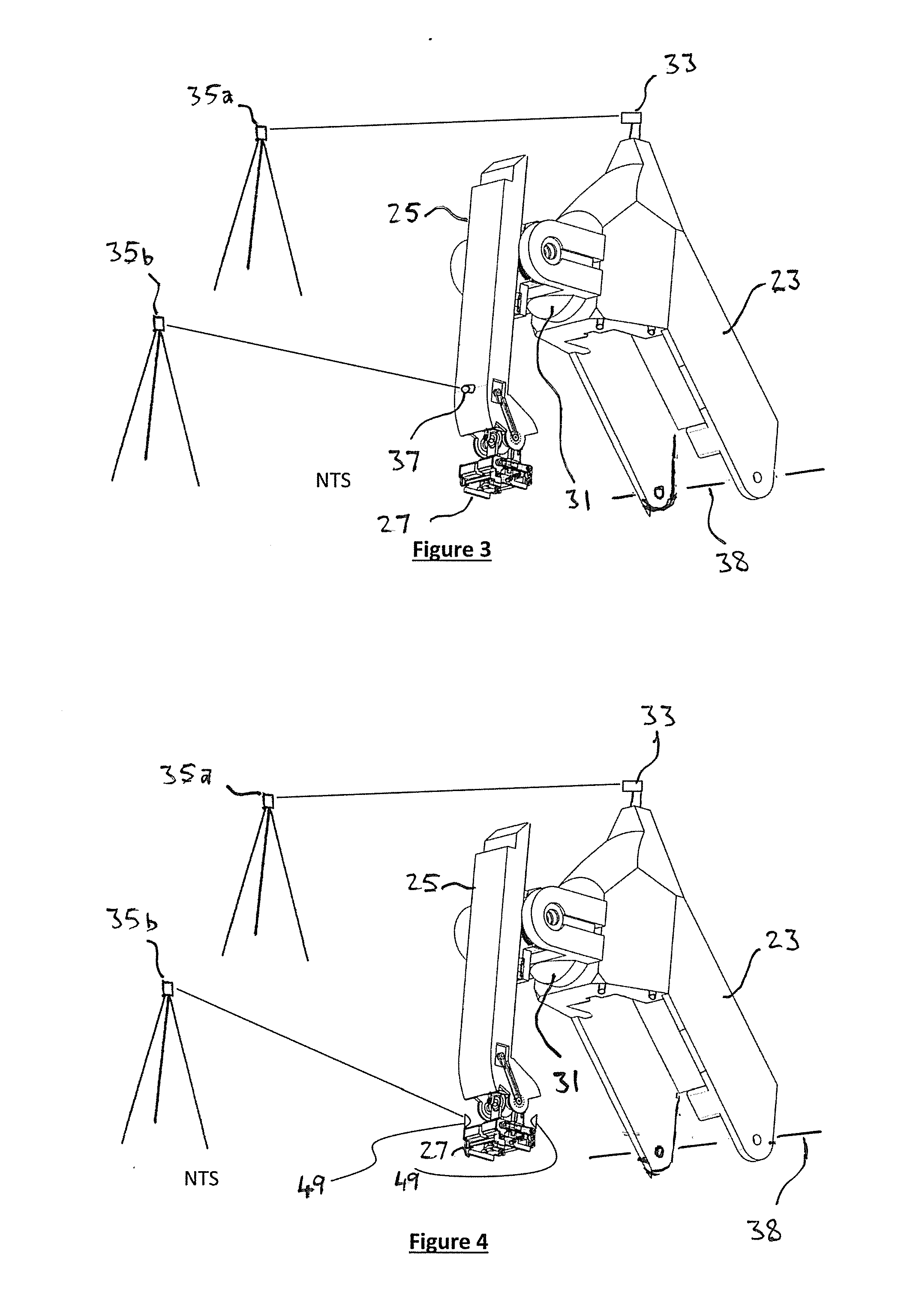
[0059] FIG. 3 is a view of the tracker system for interfacing to control the position of an end effector on the end of a boom according to the broadest embodiment of the invention;
[0060] FIG. 4 is a view of the tracker system for interfacing to control the position of an end effector on the end of a boom according to a narrower and more preferred embodiment of the invention;
[0061] FIG. 5 is a graph showing implementation of damping of movement when stabilisation of the end effector is switched between a ground based first state and a machine based second state;
[0062] FIG. 6 is a view showing operation of an embodiment showing machine based second state operation;
[0063] FIG. 7 is a view showing operation of the embodiment of FIG. 6 switched to ground based first state operation;
[0064] FIG. 8 is a top plan view showing use of an embodiment being a mobile block laying machine incorporating the control system of the invention, in use to build a sound proofing wall along a freeway/motorway;
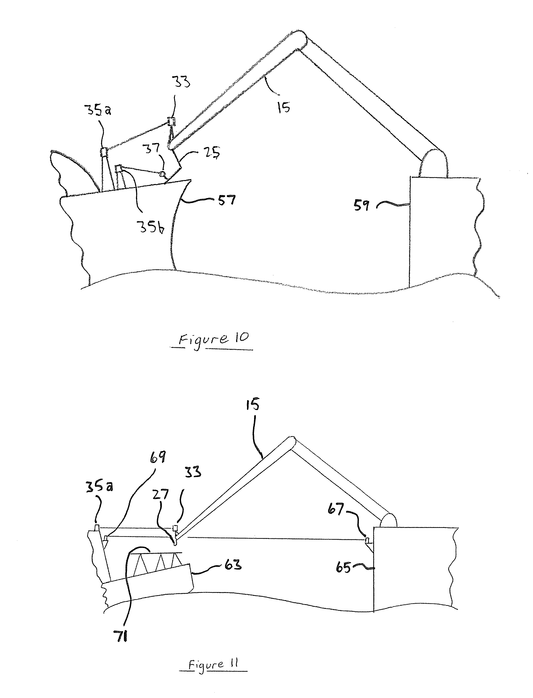
[0065] FIG. 9 is a side view showing use of a boom with a robotic arm mounted to a floating facility, in use to transfer items from a vessel subject to movement in ocean swell; and
[0066] FIG. 10 is a view of detail of the embodiment illustrated in FIG. 9; and
[0067] FIG. 11 is a view showing use of a boom with a robotic arm mounted to an oil rig, in use to transfer items from a supply vessel subject to movement in ocean swell.
DESCRIPTION OF EMBODIMENTS
[0068] The control systems and methods of the invention have been developed by the inventor in connection with an automated brick laying machine 11. For a more detailed description of the brick laying machine, reference is made to the patent specification titled "Brick/Block Laying Machine Incorporated in a Vehicle" which is the subject of international patent application PCT/AU2017/050731, the contents of which are incorporated herein by cross-reference.
[0069] The automated brick laying machine 11 is built around a vehicle in the form of a truck 13 and has a base supporting a telescoping articulated boom assembly indicated generally at 15, comprising long telescopic boom 17 and telescopic stick 19. Mounted to the remote end 21 of the stick 19 is an end effector in the form of a laying head 23 that supports a 6 axis robot arm 25 that moves a further end effector 27 to manipulate the bricks 29. The robot arm 25 has a robot base 31, and mounted above the robot base 31 is a first target in the form of a 6 degree of freedom (6 DOF) high data rate position sensor 33, that provides 6 DOF position coordinates, relative to a fixed ground reference 35, to a control system. Mounted on the end of the robot arm 25 immediately above the end effector 27 is a second target in the form of a 6 degree of freedom (6 DOF) high data rate position sensor 37, that provides 6 DOF position coordinates, relative to the fixed ground reference 35, to the control system.
[0070] The head 23 is supported at the remote end of the stick assembly 19 (remote end of the boom 15) about a pivoting horizontal axis 38 (horizontal with reference to the state of the vehicle 13, assuming the vehicle is stabilised level, absent any torsion).
[0071] In a general embodiment, the vehicle 13 supports a boom 15 which supports a robotic arm 25 that supports an end effector 27. The head 23 may optionally be omitted between the boom 15 and the robot arm 25, but given the tasks to be performed by the end effector 27, particularly the application of adhesive in a brick laying application, it is more practical to include the head 23.
[0072] The vehicle 13 may be parked stationary or jacked up on support legs 39. As an alternative, the vehicle 13 may be programmed with a first CNC channel to move, or may be manually driven, along a path. In this case a further third target in the form of a 6 degree of freedom (6 DOF) high data rate position sensor 41 is provided, that also provides 6 DOF position coordinates, relative to the fixed ground reference 35, to the control system. Where the vehicle traverses a path in this manner, there will need to be multiple fixed ground references of the same type of the fixed ground reference 35. Alternatively, in another embodiment, a low data rate and low accuracy position sensor such as GPS could be utilised, but high data rate is preferred.
[0073] For faster data handling it may be desirable to have multiple ground references 35a, 35b, 35c, each dedicated to their respective sensor 33, 37 and 41, as illustrated in FIG. 2.
[0074] The boom 15 is programmed with a second CNC channel to move the TCP of its end effector (located at the tip) of the boom to the required coordinates.
[0075] The robot arm 25 is programmed with a third CNC channel to move the TCP of its end effector 27 to conduct tasks.
[0076] Optionally the end effector 27 may include a fine dynamic compensation mechanism for very accurate work. Such a system may include a galvo mirror to be used with a high power laser for laser cutting, engraving or 3D additive laser melting manufacture. The end effector is programmed with a fourth CNC channel to move the TCP of the fine dynamic compensation mechanism.
[0077] Referring to FIG. 4, detail of the most preferred embodiment is shown. A control system is provided for the boom 15 supported from a boom base in the form of the truck 13. The boom 15 has the head 23 mounted about a horizontal pivot axis 38 at the remote end of the stick assembly 19. The robot arm 25 is mounted by the robot base 31 to the head 23. The end effector 27 which comprises a gripper to pick up bricks is mounted for pitch roll and yaw movement to the end of the robot arm 27. The control system includes a boom controller interfaced with a boom actuator in the form of hydraulic rams 45 and 47 (and a rotating mechanism within the truck body--not shown) to move the boom 15 relative to the vehicle 13 by to position the head 23 and hence the robot base 31 to a programmed location. The control system also includes a robot arm controller interfaced with a robot arm actuator to position said end effector at a programmed position and orientation. The tracker system has fixed ground reference 35a to track the position of the first target 33 located by an offset proximal to the robot base 31. The tracker system has fixed ground reference 35b to track the position and orientation of one of two second targets 49 (whichever is visible) located with a TCP offset from the TCP of the end effector 27. The tracker system tracks the position of the first target 33 and feeds data to said boom controller to operate said boom actuator with a slow dynamic response to dynamically position said first target 33 close to said offset to position said robot base 31 close to said programmed location, so that the end effector 27 is within range of the position in which it is required to perform work. Since the targets 49 move with the end effector 27, and the end effector can move with six degrees of freedom, and the tracker system tracks both the position and orientation of said second target with six degrees of freedom and feeds data to the robot arm controller to operate said robot arm actuator (including the end effector) with a fast dynamic response to dynamically position and orientate said second target to said TCP offset from said programmed position and orientation.
[0078] The control system may controllably switch control of the robot arm controller between a first state where the robot arm controller is responsive to positioning feedback data derived from the tracker system, and a second state where pre-calibrated positioning data referenced to the robot base (and hence the remote end of the boom) is relied on. The movement at the end effector 27 relative to the robot base 31 is represented by trace 51 in FIG. 5, which shows deviations due to dynamic structural effects on the boom, wind deflection or vehicle movement, and the second state position for the robot arm is indicated at 53. When switched between the first state and the second state, said robot arm controller controls movement of the robot arm to damp or smooth movement of the robot arm, through the transition between the first state and the second state, indicated by trace 55, to avoid sudden movement of the robot arm and said end effector. Such sudden movement could feed back to the boom, causing the boom to undergo reactive movement.
[0079] The switching between first and second states deals with applications that require the end effector to alternately be controlled relative to the machine structure and then the ground, for example to pick up a brick from part of the machine and then to lay a brick on a wall relative to the ground. FIG. 6 shows the end effector 27 picking up a brick from the end of the boom. In this configuration the control system is in the second state and the tracker system need only track the first target 33. FIG. 7 shows the end effector 27 about to lay the brick. In this configuration the control system is in the first state, and the tracker system must track the first target 33 and the second target 37. The control system transitions from the second state to the first state and vice versa in a slow manner, over a period of about a second, to damp the movement of the end effector. If the compensation was turned on or off immediately, the pose of the compensating robot would have to change instantly, giving very large forces and disturbance to the boom. To overcome this problem, it is necessary for the compensation to be transitioned on or off or damped so that the amount of compensation is gradually increased or decreased to the required amount over a period of time, typically 0.2 to 0.5 seconds (or up to 10 seconds for large machines, or perhaps as low as in the order of milliseconds, up to 0.1 seconds for small machines). With a dynamic base coordinate system it is necessary to achieve the transitioning effect by moving the base coordinate system from its programmed position to the actual position over a period of time. It is important to check that the amount of compensation that will be applied is within the working range of the compensation robot. This is done by checking that the pose of the robot will be within the working envelope. (If the calculated amount of compensation to be applied would move the end effector beyond its working range, or exceed the robot arm dynamic limits of jerk, acceleration, or velocity), if the actual position and orientation of the dynamic base coordinate system would place the robot in a pose beyond its working range of axis travel or the TCP outside of the working envelope of the robot arm, or exceed the end effectors dynamic limits of jerk, acceleration, or velocity the amount of shift of the base dynamic coordinate system from the programmed location to the actual location (or the application of the compensation amount), may be scaled back, or motion may be held until the system is returned to within its working range and/or a warning can be issued within the controller.
[0080] Dynamic compensation transitioning works by, incrementing if compensation is turning on, or decrementing if compensation is turning off, a transition factor between a value of 0 and 1, so that it S curve ramps over the desired period of time, then, for each control cycle: [0081] Measure the actual 6 dof coordinates of the tip tracker. Calculate the 6 DOF coordinates of the actual coordinate system of the base of the fine robot [0082] If the transition factor is 1, then use the actual coordinate system of the base of the fine robot as the dynamic coordinate system. [0083] If the transition factor is not 1 then: [0084] Determine the programmed position of the coordinate system of the base of the fine robot by considering the programmed position of the boom tip and adding the kinematic transformation to the base of the fine robot. [0085] If the transition factor is 0, then use the programmed position of the coordinate system as the dynamic coordinate system. [0086] If the transition factor is between 0 and 1 then: [0087] Calculate a 6 DOF delta vector from the programmed to the actual coordinate system of the base of the fine robot. [0088] Scale the 6 DOF vector by the transition factor to give a scaled vector [0089] Add the scaled vector to the programmed position of the coordinate system to give the dynamic coordinate system. [0090] Check the pose and dynamics to ensure that the fine robot is within its working range. Go to warning, hold or scaling algorithms. [0091] If the transition factor is less than 1, increment the transition factor, preferably using an S curve formula.
[0092] Preferably said machine includes a tracker component mounted to said head, wherein said head has said robotic arm assembly with said end effector and said machine uses a tracker system to measure the position and orientation of the tracker component and uses said measurement to calculate the position and orientation of a base coordinate system for said robotic arm assembly. The robot arm end effector TCP is programmed to do tasks in either a coordinate system fixed to the head, or in a coordinate system fixed to a workpiece (fixed to the ground). The programming can shift between the head coordinate system or the workpiece coordinate system. The switching is done by transitioning. Transitioning is explained below.
[0093] Transitioning to the dynamic base coordinate system involves moving the dynamic base coordinate system from a theoretical perfect position and orientation to an actual position and orientation (obtained by a measurement of the position and orientation of a tracker component fixed to the head), in a gradual and controlled way.
[0094] Transitioning from the dynamic base coordinate system involves moving the dynamic base coordinate system from an actual position and orientation (obtained by a measurement of the position and orientation of a tracker component fixed to the head), to the programmed (ie a theoretical) perfect position and orientation in a gradual and controlled way.
[0095] The most elegant mathematical approach to the arrangement is to have the boom TCP, tip tracker centre point and the dynamic coordinate system of the base of the robot arm coincident and aligned. In this way the kinematic transform set up in the boom CNC channel has its TCP coincident with the tip tracker centre point. The kinematic transform of the robot arm CNC channel has its dynamic base coordinate system coincident with the tip tracker.
[0096] Those skilled in the art will appreciate that the boom TCP could be at position different to the head base dynamic coordinate system and different to the tip tracker centre point and mathematical transforms can be used to calculate the theoretical perfect position of the robot arm base dynamic coordinate system. This is a more complicated and less elegant solution than that outlined above with coincident boom TCP, tip tracker CP and robot arm base dynamic coordinate system.
[0097] The control system uses a dynamic coordinate system offset or a plurality of dynamic coordinate system offsets to shift the base coordinate system of the robot arm in real time in the ground coordinate system. The control system then uses a kinematic transformation to calculate the required joint positions (angular or linear joints) to position the end effector at the programmed position in the ground coordinate system, rather than in the robot base co-ordinate system.
[0098] For large area tasks it may be necessary to move the vehicle relative to the ground. The vehicle movement relative to the ground may be automatically controlled or may be manually controlled within pre-calculated guidelines. In any case the location of the machine base is guided by either wheels or tracks, chains or rails or legs and feet and may not be very accurate. In this case, a multi stage control system is used, the first stage approximately positions the vehicle, the second stage positions a boom to a desired tip location and corrects at a slow rate any errors due to vehicle position and orientation and boom deflection and a third stage measures the position and orientation of a third stage robot arm base coordinate system and then precisely positions and compensates to stabilise and guide an end effector relative to the ground coordinate system. The number of stages of measurement and control may be extended to any plurality of control systems, dynamic coordinate systems and measurement systems. It is important for stability that the bandwidth of the control and the mechanical response speed of the motion systems increases from vehicle to end effector.
[0099] In some situations, it is necessary to stabilise the end effector relative to a moving object rather than the ground. Provided the relative position of the vehicle coordinate system and the tip tracker coordinate system is measured relative to the moving object coordinate system (or vis versa), compared to the vehicle, the moving object may be regarded as analogous to the ground, except that it is not an inertially fixed coordinate system. In this case, preferably a measurement to an inertially fixed coordinate system (eg earth or an INS, albeit a slowly rotating coordinate system) is also made to enable motion dynamic limits to be observed.
[0100] The control system can be used for tasks such as automated brick laying, precision mining, machining, robot assembly, painting and 3D printing. It has particular application for automated trenching for infrastructure pipelines, railway and road construction, automated pipe laying and for building long walls such as freeway sound wall.
[0101] The invention can be applied to airborne or seaborne equipment for applications such as dredging, seawall construction, oilfield and wind turbine maintenance, crew transfer, ship to ship transfer or air to air transfer or refuelling or helicopter powerline maintenance or helicopter logging.
[0102] The invention applies to multiple kinematic chains and multiple dynamic coordinate systems. The invention is particularly useful to stabilise, relative to the ground, an end effector, attached to a boom that is on a moving machine. When a machine moves, the acceleration of the machine imparts a dynamic force to the boom and the boom starts to oscillate at its natural frequency. Provided the compensating robot at the end of the boom has an amplitude larger than the amplitude of the boom motion, and a response much faster than the natural frequency of the boom (and vehicle), the compensating robot can correct for the boom motion due to bounce from the vehicle travel. The compensating robot does not have much range of motion so it is necessary to also correct the pose of the boom to keep the compensating robot within its available range of motion.
[0103] The actuation of the compensating robot imparts dynamic forces to the boom, which in turn further excite the boom. To minimise jerky motion of the boom, it is desirable for the boom to be rigid and free of mechanical play and backlash.
[0104] It is desirable for the (optional) moving vehicle to travel smoothly, so it is desirable for the ground it moves over to be graded and it is desirable for the vehicle to have suspension. Ideally the suspension is self-levelling. Optionally the vehicle may be fitted with a controllable blade so that it levels the ground before it drives over it. Optionally the end effector may be a blade or bucket and the machine may grade and level its own path prior to moving on to it.
[0105] To minimise jerky motion of the machine and the boom the control system of the vehicle of the machine is used to carefully control the motion. Preferably a mode of operation can be set when stabilised end effector operation is desired. The vehicle and boom motion is preferably jerk, acceleration and velocity limited. In an electro hydraulic control system, the electrical pilot system is controlled to limit the available control input. In a servo electric system, the servo dynamics are limited, preferably by the CNC channel and axis configuration. Preferably full CNC path planning is utilised rather than set point or point to point motion control. A full CNC path planner calculates path points for every control cycle (typically every ms). Preferably it calculates a path to optimise position, velocity, acceleration and jerk. A point to point control simply changes the set point to the desired end point, so that a large control feedback error value is created and the feedback control loop commands the motion to close the error.
[0106] The measurement of the vehicle position and orientation may be back calculated from the measurement of the 6 DOF tip tracker (using the inverse kinematic chain of the boom, which of course will not take into account deflection or vibration of the boom, unless it was measured for example by accelerometers, but would typically have the tip tracker motion heavily filtered to smooth the vibration component of the motion). Preferably the vehicle position and orientation is provided by a position tracking device fitted to the vehicle of the machine, or a part of the machine near the vehicle, such as the cab on an excavator. The vehicle tracking device may have a relatively low data rate and low accuracy such as GPS or total station target but the best performance would be achieved with an accurate sensor system such as a laser tracker and smart track sensor.
[0107] The motion of the boom is controlled at a bandwidth significantly less than its natural frequency (1% to 10% or 10% to 20% or 30% to 50% or 50% to 99%) so as to slowly compensate for boom motion errors and deflection and base motion errors or movement. The controlled motion of the boom aims to correct the position of the tip of the boom, but not necessarily the boom tip orientation. The boom control and response may have a bandwidth of 0.1 to 1 Hz, or 1 Hz to 10 Hz or 10 Hz to 30 Hz. The end effector compensating robot must have a high natural frequency (relative to the boom and base) and a fast dynamic response. The compensating robot compensates and stabilises in 6 DOF. The measurement system of the tip tracker must have a high data rate, preferably at the same servo loop control rate as the end effector control system, a minimum of 250 Hz and preferably 1000 Hz or greater (perhaps 10 kHz). If the data rate is significantly lower, the dynamic coordinate system position and orientation (ultimately resulting in a compensation input) has step changes that may induce structural vibration as the system responds to the actuator force inputs. If the step changes are filtered to provide a smooth change, a delay and motion lag is introduced and the end effector position is not accurate and may oscillate relative to the ground.
[0108] A chain of dynamic coordinate systems and a machine with a chain of compensating booms and robotic compensating end effectors is useful in many applications requiring fine position and motion control over a large working volume.
[0109] Some example applications are given below:
Ship Transfer
[0110] Ship to ship, or ship to oil rig, or ship to gas rig, or ship to wind turbine, transfer of goods, liquids or personnel, is a potential application for the control system of the invention. It is known to stabilise a vessel for position holding. It is also known to roll stabilise a vessel with gyros or thrusters. It is known to yaw stabilise a vessel with thrusters. It is also known to provide heave, pitch, roll and yaw compensation to working devices such as booms. However, it is known that for long booms in heavy sea states the existing methods of compensation have limitations. A coarse boom positioning and fine end effector positioning, or even additional stages of fine positioning would enable safer transfer, hook up, disconnection and operations in larger sea states and rougher weather. For example FIGS. 9 and 10 show a boom mounted on a FPSO 59 (Floating, Production, Storage and Offloading vessel) transferring LNG to a LNG tanker 57. The boom has a fine positioning arm which can approach close to or connect to the tanker. Trackers measure the relative position of the boom tip and the tip of the fine positioning arm. If the fine positioning arm is connected or engaged with the tanker 57, the control system is switched to a passive mode (ie no active control) so that the fine positioning arm now acts as a suspension system to absorb relative movement between the boom tip and the tanker.
[0111] Referring to FIG. 11, a platform stabilised in six degrees of freedom by a Stewart Platform 71 on the deck of a supply vessel 63, relative to an oil or gas rig 65 or FPSO (Floating Production Storage and Offloading vessel), as illustrated, would enable much safer transfer of goods and personnel using the existing cranes on the rig or FPSO. Tracker 67 on the rig 65 tracks target 69 on the vessel 63, while tracker 35a on the vessel tracks target 33 at the end of the boom 15. This data is fed to the control system located with the base of the boom on the rig via radio link as necessary to control the boom 15 and end effector 27 as discussed, and may also be fed back to assist to control the Stewart Platform 71 on the deck of the vessel 63. This provides a particularly significant operating advantage for handling large and expensive items. Currently when sea state reaches a limit, transfers have to be stopped.
[0112] This could have great benefit for petrochemical, renewable energy and military operators (and others) who require or desire to transfer things from vessel to vessel or vessel to fixed objects in all weather conditions.
Long Building
[0113] Long structures such as road freeway sound walls 61 can be built by the brick laying machine, however with the arrangements described to date in the patent application 20169 it is necessary to build from one location, then reposition periodically and build from the next stationary location. It would be advantageous to be able to build from a creeping machine. This would reduce lost time to reposition and would enable a smaller more compact machine with a shorter boom. A track mounted machine with a short boom would be ideal. Multiple fixed ground references 35 are provided to facilitate this, as shown in FIG. 8.
Long Trenching
[0114] Long trenches for infrastructure such as underground pipe lines and underground cables can be dug with known continuous trenching machines (such as made by Ditch Witch or Vermeer) or for larger cross section trenches with excavators (such as made by Caterpillar, Volvo, John Deere, Komatsu and others). For many applications the precise grade and location of the trench and pipe is important, such as for sewerage pipe. For many applications knowing the precise position is important, such as in cities to avoid damaging existing infrastructure such as pipes, cables, foundations and underground train and road tunnels. Current systems allow some control of the digging and provide feedback to the operator of dig depth or bucket position. In current system the base of the machine (the tracks) must be stationary.
[0115] The dynamic control system described allows precision digging to a tolerance that cannot be currently achieved by other methods. Further-more it allows pre-programmed digging for completely autonomous operation. Further-more it allows precision digging from a continuously moving machine such as a tracked excavator creeping along the path of the proposed trench.
Ground Contouring
[0116] It is known to use graders, bulldozers, loaders, gradall or automated screeding machines to smooth earth or concrete surfaces with blades or buckets. The inherent design of the machine will achieve a flatter surface than it moves over because the geometry of the machine provides a smoothing action. It is known that a more accurate and faster result can be achieved with automatic control to maintain the bucket or blade on a predefined level, grade or contour. The blade or bucket is moved up or down or tilted about a roll axis automatically to maintain a laser plane level or grade or to match a contour referenced by GPS or total station measurements. These known control systems have a low bandwidth and the machine achieves an accurate result because the inherent design of the machine will achieve a flatter surface than it drives over, even without machine guidance.
[0117] The present invention allows more complex machine arrangements such as a (modified) excavator, to be fitted with a multi axis controlled blade or bucket to achieve very complex earthmoving tasks in a completely programmable way.
Mining
[0118] It is known to use autonomous trucks for mining.
[0119] Excavators and face shovels are currently operated by machine operators. This technology enables autonomous control of excavators and face shovels by pre-programming the base movement (track base) and the dig program in mine coordinates.
Dredging
[0120] Excavators mounted on barges are used for dredging. Dredged channel depth, width, profile and location is extremely important for shipping safety. Dredging is expensive so it is advantageous to minimise the amount of spoil moved. The more accurate the dredging, the less spoil needs to be removed.
[0121] The barges are floating so as the excavator moves, the barge pitches and rolls and moves. Measuring the barge position and orientation in 6 dof in real time enables the bucket position to be precisely calculated (via known sensors that measure the pose of the excavator), or even controlled to a set of pre-programmed dig locations.
Elevated Work Platforms
[0122] It is known to use various kinds of elevated work platforms (EWP) such as boom lifts or scissor lifts or vertical telescoping lifts made by manufacturers such as JLG, Snorkel and Genie. It is known that very tall boom lifts sway with a large amplitude and make work difficult, dangerous or impossible. The sway is the limiting factor for the height that boom lifts can work at. It is known that driving the boom lift or EWP with the platform up excites sway and makes the platform uncomfortable or dangerous. The present invention provides means to make a stabilised platform so that the platform is stabilised relative to the ground, or to a desired trajectory when the platform or EWP is moved.
Cable Suspended Robots
[0123] It is known to support a robot on a platform suspended by cables in tension supported by an overhead gantry or towers (see PAR Systems--Tensile Truss and Chernobyl Crane and demolition robot). The cables can support high loads but the structure has low stiffness. The lateral stiffness is very low. The accuracy of the positioning of the robot and end effector would be greatly improved by adding a tracking component to the suspended platform to provide a 6 DOF position of the base of the robot arm. This would enable such a system to do accurate work, rather than the relatively inaccurate demolition work it is presently employed to do.
Very Accurate Applications
[0124] Such a system may include a galvo mirror to be used with a high power laser for laser cutting, laser engraving or 3D additive laser melting manufacture.
[0125] It should be appreciated that the scope of the invention is not limited to the specific embodiments described herein.
* * * * *
D00000
D00001
D00002
D00003
D00004
D00005
XML
uspto.report is an independent third-party trademark research tool that is not affiliated, endorsed, or sponsored by the United States Patent and Trademark Office (USPTO) or any other governmental organization. The information provided by uspto.report is based on publicly available data at the time of writing and is intended for informational purposes only.
While we strive to provide accurate and up-to-date information, we do not guarantee the accuracy, completeness, reliability, or suitability of the information displayed on this site. The use of this site is at your own risk. Any reliance you place on such information is therefore strictly at your own risk.
All official trademark data, including owner information, should be verified by visiting the official USPTO website at www.uspto.gov. This site is not intended to replace professional legal advice and should not be used as a substitute for consulting with a legal professional who is knowledgeable about trademark law.