Air Cleaner Frame
Wiser, III; Forwood C. ; et al.
U.S. patent application number 16/115268 was filed with the patent office on 2019-07-25 for air cleaner frame. This patent application is currently assigned to Environmental Management Confederation, Inc.. The applicant listed for this patent is Environmental Management Confederation, Inc.. Invention is credited to Aditya A. Patel, George Robert Summers, Forwood C. Wiser, III.
| Application Number | 20190224603 16/115268 |
| Document ID | / |
| Family ID | 50431641 |
| Filed Date | 2019-07-25 |


| United States Patent Application | 20190224603 |
| Kind Code | A1 |
| Wiser, III; Forwood C. ; et al. | July 25, 2019 |
AIR CLEANER FRAME
Abstract
An air filter has a mechanism for preventing blow-by around a perimeter of the filter. The air filter has two rigid frames surrounding a filter and at least one of the rigid frames comprises a brush seal track with a brush seal therein. The air filter includes a latching mechanism to engage the rigid frames to each other and a handle for installation and removal.
| Inventors: | Wiser, III; Forwood C.; (Kingston, NJ) ; Patel; Aditya A.; (Iselin, NJ) ; Summers; George Robert; (Carleton Place, CA) | ||||||||||
| Applicant: |
|
||||||||||
|---|---|---|---|---|---|---|---|---|---|---|---|
| Assignee: | Environmental Management
Confederation, Inc. Rocky Hill NJ |
||||||||||
| Family ID: | 50431641 | ||||||||||
| Appl. No.: | 16/115268 | ||||||||||
| Filed: | August 28, 2018 |
Related U.S. Patent Documents
| Application Number | Filing Date | Patent Number | ||
|---|---|---|---|---|
| 14040093 | Sep 27, 2013 | 10058809 | ||
| 16115268 | ||||
| 61706318 | Sep 27, 2012 | |||
| Current U.S. Class: | 1/1 |
| Current CPC Class: | B01D 46/0002 20130101; B01D 46/10 20130101; B01D 46/0097 20130101 |
| International Class: | B01D 46/00 20060101 B01D046/00; B01D 46/10 20060101 B01D046/10 |
Claims
1. An air filter comprising: two rigid frames surrounding a filter, wherein at least one of the rigid frames includes a rail; a latch mechanism located on the rail that removably engages the rigid frames to one another.
2. The air filter of claim 1, wherein the rail defines a channel therein, and the latch mechanism is located within the channel.
3. The air filter of claim 1, wherein the latch mechanism does not extend outside the channel when the latch mechanism is in an engaged position.
4. The air filter of claim 1, wherein the latch mechanism includes a thumb portion and a catch portion attached to one of the two rigid frames.
5. The air filter of claim 4, wherein the catch portion engages a pin on the other of the two rigid frames.
6. The air filter of claim 1, wherein the latch mechanism is a screw type latch including a screw attached to one of the rigid frames that engages a tab attached to the other of the rigid frames.
7. The air filter of claim 1, wherein the latch mechanism is a magnetic latch attached to one of the rigid frames that engages a magnet attached to another of the rigid frames.
8. The air filter of claim 1, An air filter comprising: two rigid frames surrounding a filter, wherein at least one of the rigid frames includes a rail, wherein the frames are attached in parallel using magnetic strips.
9. The air filter of claim 8, wherein a magnetic strips are mounted on one of the two rigid frames.
10. The air filter of claim 8, wherein the magnetic strips are mounted on both of the two rigid frames.
11. An air filter comprising: two rigid frames surrounding a filter, wherein at least one of the rigid frames includes a rail, wherein the two rigid frames are hingedly attached to one another; and a handle attached to a rail.
12. The air filter of claim 11, wherein the handle is located along an edge of a frame.
13. The air filter of claim 12, wherein the handle is a d-ring.
14. The air filter of claim 13, wherein the handle is a pull handle.
Description
BACKGROUND
[0001] Polarized media and other active field air cleaners are typically designed so that two framed screens are hinged and latched together. The frames are typically made of a rigid material such as a rolled or extruded aluminum rail. Hinges and latches are attached to these.
[0002] There are issues, however, with this approach to air cleaners that slide into a track. First, the tracks themselves are made of metal and are not consistently fabricated unit to unit. Therefore to ensure that the frames will slide into the tracks, the frames are often undersized and will not seal tightly. This results in blow-by of air around the air cleaner that is not cleaned, degrading system performance. Second, this is exacerbated by the fact that if the latches and hinges protrude from the surface of the frame, the frame must be undersized to accommodate that dimension, ie the frame will have to be even smaller allowing for more blow-by.
[0003] Third, the tracks themselves are often attached with screw or rivets and the latches and hinges of the air cleaner typically protrude from the surface of the frame and can catch on the rivets and screws, making service and installation difficult.
[0004] Fourth, in many cases, the construction of the track and overall duct system is such that there is ductwork or other sheet metal on either side of the track opening. Here, the filter can slide into the track and be flush or recessed relative to the surrounding structures. Therefore, once the filter is installed in the track, there is no surface by which one can easily get a hold on the air cleaner when it needs to be pulled out and removed for service and media replacement. This makes it harder to remove an air cleaner from the track and can lead to damage of the air cleaner when tools such as pliers or screwdrivers are used to remove the filter.
SUMMARY OF THE EMBODIMENTS
[0005] An air filter has a mechanism for preventing blow-by around a perimeter of the filter. The air filter has two rigid frames surrounding a filter and at least one of the rigid frames comprises a brush seal track with a brush seal therein.
BRIEF DESCRIPTION OF THE DRAWINGS
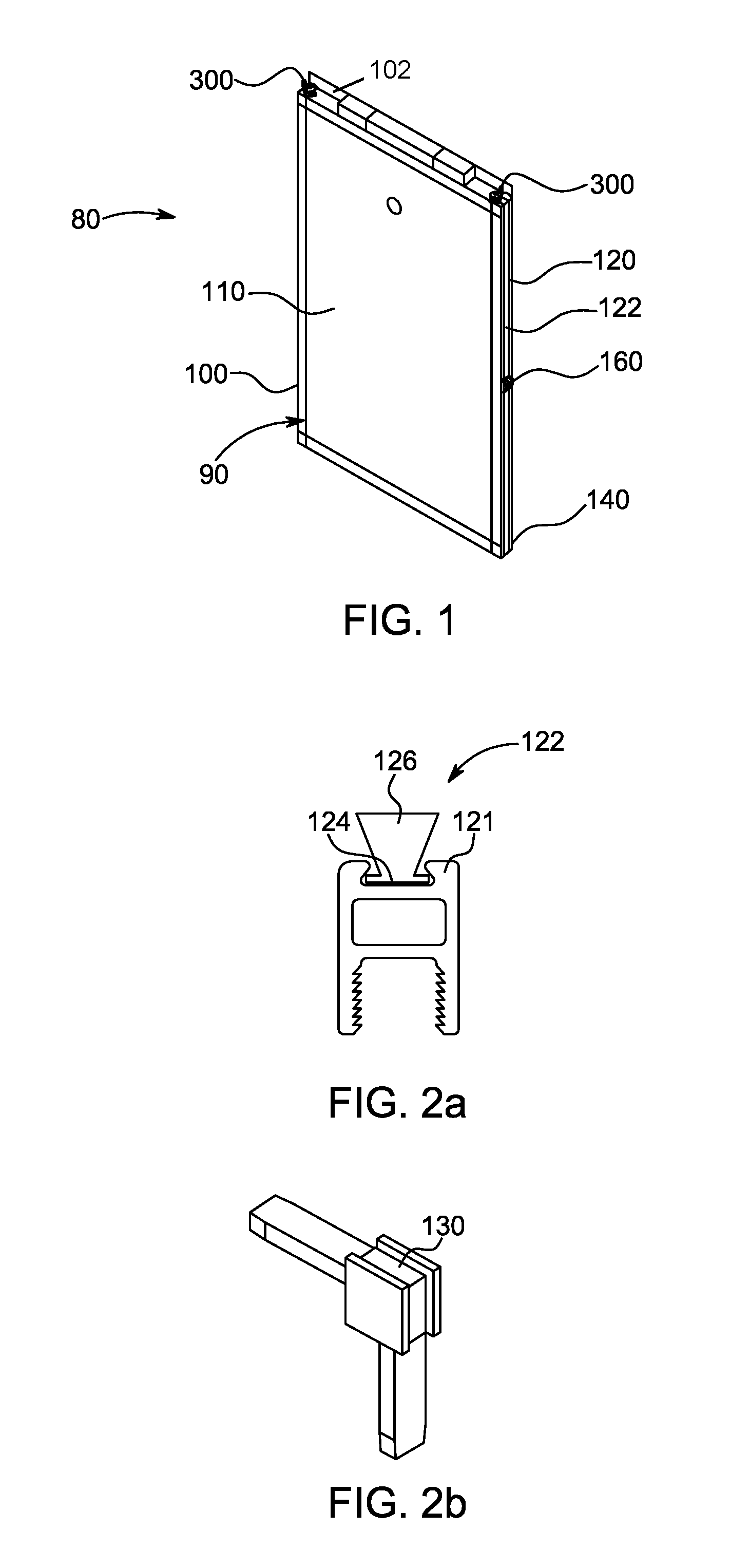
[0006] FIG. 1 is an isometric view of a filter and frame.
[0007] FIGS. 2a-2d show different views of a frame.
[0008] FIG. 3 shows an alternate embodiment of a frame.
[0009] FIGS. 4a-4c show embodiments of a latch on a frame.
[0010] FIG. 5 shows an alternate embodiment of a frame.
[0011] FIG. 6 shows another alternate embodiment of a frame.
[0012] FIGS. 7a-7c show embodiments of a frame with seals therein.
[0013] FIGS. 8, 9a and, 9b show handle embodiments mounted on a frame.
DETAILED DESCRIPTION OF THE EMBODIMENTS
[0014] The following filter embodiments address the issues described above. FIG. 1 shows an air cleaner 80 for insertion into an air handling unit (not shown). The air cleaner 80 includes a frame structure 90 comprising two frames 100 that hold a filter material between them and behind a mesh screen, within the area shown by reference number 110. The frame 100 may include a brush seal track 120 with a brush seal 122 therein that has been added to frame, corners 140, a handle 160, an extruded "live" hinge 200 (see FIG. 3), and a latch 300. The track 120 may accommodate a range of brush sizes, as shown in FIG. 7. to allow for custom fitting of the air cleaner 80 into the available filter track. The latch 300 has been designed to fit within the frame dimensions as shown in FIGS. 4a-4c. The pull or handle 160 provides an end user with a handhold for air cleaner 80 removal and service.
[0015] Looking at the brush seal 122 that is shown in more detail in FIGS. 2a-2d, 4 (within hinge 200), and 7a-7c, the brush seal 122 has an engagement portion 124 and sealing portion 126. The seal's engagement portion 124 is contained within the brush seal track 120 that has tabs 121 that wrap around the engagement portion 124 and hold the seal 120 to the frame 100. A similar track with tabs 121 may be used in a corner piece 130 (often but not always made from plastic) on the frame 100 to minimize leakage as shown in FIG. 2b. As shown in FIGS. 2c and 2d, the track can be a dovetail track 121a or slot track 121b.
[0016] The frames 100 are joined together in parallel using a hinge element 200. The hinge element 200, which may be flexible along a flexing portion 226, has at least two tracks 220, with tabs 221 that contain a seal 122. The hinge element 200 includes hinge element engagement portions 224 that engage within the frame track 120 and tabs 121. The hinge element 200 with the seal 122 capability provides better sealing around the hinge 200 in use.
[0017] As shown in FIGS. 4a-4c, another feature of the frame 100 along a rail 102 (this would likely be located at a rail opposite the location of the hinge 200 is a latching element 300, 320, or 340. Each of the 3 latching elements 300, 320, and 340 serve the same purpose of securing the frames 100a and 100b to one another, but the latching elements 300, 320, 340 are within an open channel 103 defined in the rail 102, and have a low profile that does not extend beyond the top of the channel 103 in an engaged position, and other low profile latches are possible beyond these 3 shown herein. The thumb latch 300 has a thumb portion 302 that helps an end user move the latch 300 and a catch portion 304 that secures a pin 306 to secure the first frame 100a to the second frame 100b. In another version, the latch 320 includes a screw 322 engaged to a threaded tab 324. When tightened, the screw 322 engages a filter mating tab 326 to secure the frame 100a to the frame 100b. In another version, the latch 340 includes mating magnets 342, 344, one attached to the frame 100a and the other to the frame 100b to secure them together. It should be appreciated that in each of the embodiments in FIGS. 4a-4c, a latching element on each frame comes together with a latching element on the other frame to join the frames 100a, 100b together. This allows the frames 100a, 100b to be separated in a clamshell way using the hinge element 200, such that the frames 100a, 100b can be opened for filter material insertion and maintenance.
[0018] As shown in FIG. 5, two frames 100 may also be joined together in addition to the hinge element 200 and latch elements or in their place, using magnetic strips 500 attached to the frames 100. The strips 500 would engage one another so that the frames 100 and filters 110 therein would be side-by-side.
[0019] As shown in FIG. 6, an improved frame 100 may comprise a thicker extrusion (aluminum with a thickness greater than 0.24'' or steel) that may have a spline 600 and/or steel mesh screen 602 in place of a more lightweight screen. Such a reinforcement helps to resist lateral forces through the air filter 80. Other forces, especial torsional diagonal forces may be resisted by inserting a steel mesh 602 that may be frictionally held in place with a spline 600. These reinforcing elements may be desirable in higher stress environments or just to minimize bending and breakage in normal environments.
[0020] FIGS. 8, 9a, and 9b show variations of a handle 160, 180 installed along the frame track 120. FIG. 8 shows a D-ring handle 160 attached to the frame 100 using a screw 162. The D-ring 164 rotates about an axis through a conduit 166 when being used. FIG. 8 shows a pull handle 180 (in two views) engaged to the frame in the track 120. Both handles allow for easier movement of the frame 100.
* * * * *
D00000
D00001
D00002
D00003
D00004
D00005
D00006
XML
uspto.report is an independent third-party trademark research tool that is not affiliated, endorsed, or sponsored by the United States Patent and Trademark Office (USPTO) or any other governmental organization. The information provided by uspto.report is based on publicly available data at the time of writing and is intended for informational purposes only.
While we strive to provide accurate and up-to-date information, we do not guarantee the accuracy, completeness, reliability, or suitability of the information displayed on this site. The use of this site is at your own risk. Any reliance you place on such information is therefore strictly at your own risk.
All official trademark data, including owner information, should be verified by visiting the official USPTO website at www.uspto.gov. This site is not intended to replace professional legal advice and should not be used as a substitute for consulting with a legal professional who is knowledgeable about trademark law.