Anterior Chamber Drug-eluting Ocular Implant
Heitzmann; Harold ; et al.
U.S. patent application number 16/372167 was filed with the patent office on 2019-07-25 for anterior chamber drug-eluting ocular implant. The applicant listed for this patent is GLAUKOS CORPORATION. Invention is credited to Harold Heitzmann, Vanessa Tasso.
| Application Number | 20190224046 16/372167 |
| Document ID | / |
| Family ID | 65898451 |
| Filed Date | 2019-07-25 |


View All Diagrams
| United States Patent Application | 20190224046 |
| Kind Code | A1 |
| Heitzmann; Harold ; et al. | July 25, 2019 |
ANTERIOR CHAMBER DRUG-ELUTING OCULAR IMPLANT
Abstract
Disclosed herein are drug delivery ocular implants comprising an elongate outer shell having a proximal end, and distal end and being shaped to define an interior lumen, at least one therapeutic agent positioned within the lumen, wherein the outer shell has at least a first thickness, the outer shell comprises one or more regions of drug release, and the implant is dimensioned for implantation within the anterior chamber of the eye.
| Inventors: | Heitzmann; Harold; (Laguna Hills, CA) ; Tasso; Vanessa; (Laguna Hills, CA) | ||||||||||
| Applicant: |
|
||||||||||
|---|---|---|---|---|---|---|---|---|---|---|---|
| Family ID: | 65898451 | ||||||||||
| Appl. No.: | 16/372167 | ||||||||||
| Filed: | April 1, 2019 |
Related U.S. Patent Documents
| Application Number | Filing Date | Patent Number | ||
|---|---|---|---|---|
| 13490346 | Jun 6, 2012 | 10245178 | ||
| 16372167 | ||||
| 61494085 | Jun 7, 2011 | |||
| Current U.S. Class: | 1/1 |
| Current CPC Class: | A61M 2205/0266 20130101; A61F 2210/0004 20130101; A61K 9/0051 20130101; A61M 2210/0612 20130101; A61K 9/2072 20130101; A61F 2220/00 20130101; A61M 31/002 20130101; A61F 2250/0068 20130101; A61M 2205/04 20130101; A61F 9/0017 20130101 |
| International Class: | A61F 9/00 20060101 A61F009/00; A61M 31/00 20060101 A61M031/00; A61K 9/00 20060101 A61K009/00 |
Claims
1.-21. (canceled)
22. A drug delivery ocular implant comprising: an outer shell having an open proximal end and a distal end, the outer shell being shaped to define an interior cavity; at least one therapeutic agent positioned within the interior cavity; a material covering the open proximal end, the material of increased permeability to the at least one therapeutic agent relative to a permeability of the outer shell; and a retention protrusion is configured to retain the implant within an irido-corneal angle of an eye.
23. The implant of claim 22, wherein the retention protrusion comprises at least one ridge.
24. The implant of claim 22, wherein the at least one orifice is positioned on the proximal end of the outer shell.
25. The implant of claim 22, wherein the retention protrusion is positioned on the distal end of the outer shell.
26. The implant of claim 22, wherein the permeability of the material is configured to module a release rate of the at least one therapeutic agent.
27. The implant of claim 22, wherein the at least one therapeutic agent comprises one or more of prostaglandins, prostaglandin analogs, alpha-blockers, beta-blockers and combinations thereof.
28. The implant of claim 27, wherein said at least one therapeutic agent is selected from the group consisting of: latanoprost, travoprost, timolol, and brimonidine.
29. The implant of claim 22, wherein the therapeutic agent is an anti-vascular endothelial growth factor (anti-VEGF) drug.
30. The implant of claim 29, wherein the anti-VEGF drug is selected from the group consisting of: ranibizumab (LUCENTIS.TM.), bevacizumab (AVASTIN.TM.), pegaptanib (MACUGEN.TM.), sunitinib, and sorafenib.
31. The implant of claim 22, wherein the retention protrusion is configured to anchor to an ocular tissue.
32. The drug delivery ocular implant of claim 31, wherein the ocular tissue comprises the sclera.
33. The implant of claim 22, wherein the implant is configured to elute the at least one therapeutic agent through the material for targeted delivery to the anterior chamber of the eye.
34. The implant of claim 22, wherein the implant is shaped and sized so as to be suitable for implantation within the anterior chamber of the eye.
35. The implant of claim 22, wherein the outer shell is biodegradable.
36. The implant of claim 22, wherein the material is biodegradable.
Description
CROSS-REFERENCE TO RELATED APPLICATIONS
[0001] This application claims the benefit of U.S. Provisional Application No. 61/494,085, filed Jun. 7, 2011, the entirety of which is incorporated by reference herein.
BACKGROUND
Field of the Invention
[0002] This disclosure relates to implantable intraocular drug delivery devices structured to provide targeted and/or controlled release of a drug to a desired intraocular target tissue and methods of using such devices for the treatment of ocular diseases and disorders of the anterior chamber of the eye including, but not limited to, indications of glaucoma, ophthalmic anterior segment disorders such inflammatory conditions (iritis, anterior uveitis or iridocyclitis, conjunctivitis), ocular infection (anti-infective therapies) and dry eye, and ocular surface disease. In certain embodiments, diseases or conditions associated with the posterior chamber of the eye are concurrently or alternatively treated. In certain embodiments, several embodiments relate to treatment of ocular disorders wherein a drug delivery device is implanted within the anterior chamber of the eye.
Description of the Related Art
[0003] The mammalian eye is a specialized sensory organ capable of light reception and is able to receive visual images. The retina of the eye consists of photoreceptors that are sensitive to various levels of light, interneurons that relay signals from the photoreceptors to the retinal ganglion cells, which transmit the light-induced signals to the brain. The iris is an intraocular membrane that is involved in controlling the amount of light reaching the retina. The iris consists of two layers (arranged from anterior to posterior), the pigmented fibrovascular tissue known as a stroma and pigmented epithelial cells. The stroma connects a sphincter muscle (sphincter pupillae), which contracts the pupil, and a set of dilator muscles (dilator pupillae) which open it. The pigmented epithelial cells block light from passing through the iris and thereby restrict light passage to the pupil.
[0004] Numerous pathologies can compromise or entirely eliminate an individual's ability to perceive visual images, including trauma to the eye, infection, degeneration, vascular irregularities, and inflammatory problems. The central portion of the retina is known as the macula. The macula, which is responsible for central vision, fine visualization and color differentiation, may be affected by age related macular degeneration (wet or dry), diabetic macular edema, idiopathic choroidal neovascularization, or high myopia macular degeneration, among other pathologies. Other ocular diseases or conditions include anterior segment disorders including inflammatory conditions (iritis, anterior uveitis or iridocyclitis, conjunctivitis), ocular infection and dry eye, and ocular surface disease.
[0005] Other pathologies, such as abnormalities in intraocular pressure, can affect vision as well. Aqueous humor is a transparent liquid that fills at least the region between the cornea, at the front of the eye, and the lens and is responsible for producing a pressure within the ocular cavity. Normal intraocular pressure is maintained by drainage of aqueous humor from the anterior chamber by way of a trabecular meshwork which is located in an anterior chamber angle, lying between the iris and the cornea or by way of the "uveoscleral outflow pathway." The "uveoscleral outflow pathway" is the space or passageway whereby aqueous exits the eye by passing through the ciliary muscle bundles located in the angle of the anterior chamber and into the tissue planes between the choroid and the sclera, which extend posteriorly to the optic nerve. About two percent of people in the United States have glaucoma, which is a group of eye diseases encompassing a broad spectrum of clinical presentations and etiologies but unified by increased intraocular pressure. Glaucoma causes pathological changes in the optic nerve, visible on the optic disk, and it causes corresponding visual field loss, which can result in blindness if untreated. Increased intraocular pressure is the only risk factor associated with glaucoma that can be treated, thus lowering intraocular pressure is the major treatment goal in all glaucomas, and can be achieved by drug therapy, surgical therapy, or combinations thereof.
[0006] Many pathologies of the eye progress due to the difficulty in administering therapeutic agents to the eye in sufficient quantities and/or duration necessary to ameliorate symptoms of the pathology. Often, uptake and processing of the active drug component of the therapeutic agent occurs prior to the drug reaching an ocular target site. Due to this metabolism, systemic administration may require undesirably high concentrations of the drug to reach therapeutic levels at an ocular target site. This can not only be impractical or expensive, but may also result in a higher incidence of side effects. Topical administration is potentially limited by limited diffusion across the cornea, or dilution of a topically applied drug by tear-action. Even those drugs that cross the cornea may be unacceptably depleted from the eye by the flow of ocular fluids and transfer into the general circulation. Thus, a means for ocular administration of a therapeutic agent in a controlled and targeted fashion would address the limitations of other delivery routes.
SUMMARY
[0007] In accordance with several embodiments, there is provided a drug delivery ocular implant dimensioned so as to be suitable for implantation within the anterior chamber of the eye comprising an elongate outer shell having a proximal end and a distal end, said outer shell being shaped to define an interior lumen and at least one therapeutic agent positioned within said interior lumen. In certain embodiments, the outer shell comprises at least a first thickness, wherein said outer shell comprises one or more regions of drug release.
[0008] In some embodiments, the implant is dimensioned to be positioned within the irido-corneal angle of the anterior chamber of the eye. In several embodiments, the implant's dimensions are suitable for retaining said implant within the irido-corneal angle of the anterior chamber of the eye. Some embodiments further comprise a retention protrusion for retaining said implant within the irido-corneal angle of the anterior chamber of the eye. In certain embodiments the retention protrusion comprises one or more of ridges, flexible ribs, expanding material (such as a hydrogel), biocompatible adhesives, claws, threads, rivet-like shapes, flexible barbs, barbed tips, and the like.
[0009] According to some embodiments, the implant is biodegradable. Certain embodiments employ non-biodegradable implants. In some embodiments, the outer shell comprises a non-rigid polymer, which may be either biodegradable or essentially non-biodegradable. In some such embodiments, the non-rigid polymer is selected from the group consisting of silicone elastomer, polyurethane, and silicone-polyurethane co-polymer. In additional embodiments, other non-rigid polymers may be used to make the outer shell, or to make other features of the implants disclosed herein.
[0010] According to some embodiments, the interior lumen has positioned within it at least one therapeutic agent that acts on therapeutic targets in the eye, including the anterior segment of the eye. In addition to being placed in the interior or lumen of an implant, the therapeutic agents may also be coated onto an implant, or otherwise be included within the structure of the implant (e.g., co-extruded into the shell material), or some combination of these methods of including a therapeutic agent with the implant. In some embodiments, the therapeutic target is at least the ciliary body. Other anterior chamber tissues are targeted in other embodiments. In still other embodiments, anterior chamber tissues are targeted in conjunction with one or more posterior chamber targets. In several embodiments, said at least one therapeutic agent is one or more of prostaglandins, prostaglandin analogs, alpha-blockers, or beta-blockers. In some embodiments, said at least one therapeutic agent is selected from the group consisting of latanoprost, travoprost, timolol, and brimonidine. In several embodiments, said at least one therapeutic agent is capable of acting on a therapeutic target in the posterior segment of the eye to treat retinal disease (or other posterior chamber malady). In certain embodiments, said at least one therapeutic agent is capable of acting as a neuroprotectant to provide a therapeutic effect to at least one of the optic nerve or retinal ganglion cells.
[0011] According to several embodiments, certain implants comprising one or more regions of drug release are configured to modulate the release rate of the at least one therapeutic agent from the lumen of said implant. In certain embodiments, said outer shell is semi-permeable to the at least one therapeutic agent. In some embodiments, said outer shell is substantially impermeable to the at least one therapeutic agent and comprises one or more orifices for elution of said at least one therapeutic agent. In several embodiments, said one or more orifices further comprise a material that is semi-permeable to said at least one therapeutic agent. According to some embodiments, said outer shell has at least a second thickness that is less than said first thickness, thereby forming a region of reduced thickness in said outer shell for elution of said at least one therapeutic agent. In several embodiments, combinations of one or more orifices, semi-permeable or substantially impermeable materials, and regions of varied thickness are used to tailor the release of the therapeutic agent from the implant.
[0012] According to several embodiments, said at least one therapeutic agent is configured to have a modulated release rate from the implant. In some embodiments, said at least one therapeutic agent is compounded with an excipient that modulates the elution of the drug into ocular fluid. In several embodiments, said at least one therapeutic agent is blended or coated with a polymer that modulates the elution of the drug into ocular fluid. In certain embodiments, said at least one therapeutic agent is formulated as one or more micro-tablets.
[0013] In accordance with several embodiments, there is disclosed a method for delivering an ocular implant as herein disclosed, comprising advancing a needle comprising an actuator and containing one or more ocular implants through the corneal tissue of the eye of a subject thereby creating an incision in said corneal tissue, wherein said incision is proximate to the limbus, advancing the needle to a position adjacent to the irido-corneal angle; activating said actuator and expelling said one or more ocular implants from the needle, wherein said expulsion results in said one or more ocular implants becoming substantially immobilized in the irido-corneal angle; and withdrawing said needle.
[0014] In accordance with several embodiments, there is disclosed a drug delivery ocular implant design for implantation within the irido-corneal angle of the anterior chamber of the eye comprising an elongate outer shell shaped to define an interior lumen containing at least a first active drug, wherein said outer shell has a length between about 5 mm and about 11 mm and a diameter between about 0.3 mm and about 0.7 mm. In certain embodiments, said at least a first active drug is embodied in one or more micro-tablets. In some embodiments, said outer shell has a first thickness. In several embodiments, said outer shell comprises one or more regions of drug release. And some embodiments, said outer shell further comprises a retention protrusion.
[0015] According to several embodiments, said outer shell has a length between about 6 mm and about 10 mm. In certain embodiments, said outer shell has a length between about 7 mm and about 9 mm. In further embodiments, said outer shell has a diameter between about 0.4 mm and about 0.6 mm. Moreover, in some embodiments, said outer shell has a length of about 8 mm and a diameter of about 0.5 mm.
[0016] According to several embodiments, said elongate shell is formed by extrusion. In some embodiments, said retention protrusion comprises one or more of ridges, claws, threads, flexible ribs, rivet-like shapes, flexible barbs, barbed tips, expanding material (such as a hydrogel), and biocompatible adhesives. In certain embodiments, said elongate shell comprises a biodegradable polymer.
[0017] According to some embodiments, said outer shell is permeable or semi-permeable to said drug, thereby allowing at least about 5% of the total elution of the drug to occur through the portions of the shell having said first thickness. Moreover, in certain embodiments said first active drug is present in an amount of at least 70% by weight of a total weight of the micro-tablet. In some embodiments, said micro-tablets have a surface area to volume ratio of about 13 to 17, and in some embodiments said micro-tablets are formed by utilizing one or more of processes selected from the group consisting of tabletting, lyophilization, granulation (wet or dry), flaking, direct compression, molding, and extrusion. In several embodiments said micro-tablets are configured to balance osmotic pressure between said interior lumen and the ocular environment external to an implant after implantation. In certain embodiments, said micro-tablets are coated with a coating that regulates the release of said first active drug from said micro-tablet, in some embodiments the coating is a polymeric coating. According to several embodiments, said first active drug is chosen from the following group: latanoprost, travoprost, timololis, and brimonidine.
[0018] According to several embodiments, said outer shell comprises polyurethane, and in some embodiments said polyurethane comprises a polysiloxane-containing polyurethane elastomer.
[0019] According to several embodiments, said regions of drug release are configured to allow a different rate of drug elution as compared to said elution through the outer shell. In certain embodiments, the one or more regions of drug release comprise one or more of regions of reduced thickness shell material, one or more orifices passing through the outer shell, or combinations thereof. In some embodiments, said orifices are positioned along the long axis of the implant shell. Certain embodiments additionally comprise one or more coatings that alter the rate of drug elution from the implant. Moreover, in some embodiments, the elution of said drug from said implant continues for at least a period of at least one year.
[0020] According to several embodiments, there is disclosed herein a method of treating an ocular condition or disorder in an intraocular target tissue comprising making an opening in the temporal portion of an eye to access an anterior chamber of the eye, advancing a delivery device associated with a drug delivery implant through the opening, inserting the drug delivery implant into the anterior chamber of the eye, wherein upon insertion into the anterior chamber, the implant is substantially immobilized within the irido-corneal angle of the eye, and withdrawing the delivery device from the eye, wherein drug elutes from the implant in sufficient quantity to treat an ocular condition or disorder. In some embodiments of the method, the drug elutes from the implant so as to achieve a therapeutic effect for a period of at least one year.
[0021] In accordance with one embodiment there is provided a drug delivery ocular implant designed for implantation within the irido-corneal angle of the anterior chamber of the eye comprising an elongate outer shell shaped to define a lumen, one or more micro-tablets comprising at least a first active drug, wherein the tablet(s) are positioned within the interior lumen. The outer shell of such an ocular implant has a length between about 5 mm and about 11 mm and a diameter between about 0.3 mm and about 0.7 mm. The outer shell, which has a given thickness, also comprises one or more regions of drug release and retention protrusions.
[0022] According to some embodiments, the ocular implants may further comprise one or more coatings that alter the rate of drug elution from the implant. Moreover, the rate of drug elution of any of the embodiments may continue for at least a period of at least one year or, alternatively, for a much shorter period.
[0023] Also disclosed herein is a method of treating an ocular condition or disorder in an intraocular target tissue comprising making an opening in the temporal portion of an eye to access an anterior chamber of the eye, advancing a delivery device associated with a drug delivery implant through the opening, inserting the drug delivery implant as disclosed herein into the anterior chamber of the eye, withdrawing the delivery device from the eye, wherein drug elutes from the implant in sufficient quantity to treat an ocular condition or disorder. Moreover, the drug may elute from the implant so as to achieve a therapeutic effect for a period of at least one year.
[0024] Disclosed herein is a drug delivery ocular implant. In certain embodiments, the implant comprises an elongate outer shell having a proximal end, and a distal end and being shaped to define an interior lumen and at least one therapeutic agent positioned within said interior lumen, wherein said outer shell has at least a first thickness, said outer shell comprises one or more regions of drug release, and said implant is dimensioned so as to be suitable for implantation within the anterior chamber of the eye.
[0025] Also disclosed herein is a method for delivering an ocular implant. In certain embodiments, the method comprises advancing a needle comprising an actuator and containing one or more ocular implants through the eye in the area of the limbus, advancing the needle to a position adjacent to the irido-corneal angle, activating said actuator and expelling said one or more ocular implants from the needle wherein said expulsion results in said one or more ocular implants becoming substantially immobilized in the irido-corneal angle, and withdrawing said needle.
[0026] Also disclosed herein is a drug delivery ocular implant design for implantation within the irido-corneal angle of the anterior chamber of the eye. In certain embodiments, the implant comprises an elongate outer shell shaped to define an interior lumen and one or more micro-tablets comprising at least a first active drug, wherein said one or more micro-tablets are positioned within said interior lumen, said outer shell has a length between about 5 mm and about 11 mm and a diameter between about 0.3 mm and about 0.7 mm, said outer shell has a first thickness, said outer shell comprises one or more regions of drug release, and said outer shell further comprises a retention protrusion.
[0027] Also disclosed herein is a method of treating an ocular condition or disorder in an intraocular target tissue. The method comprises making an opening in the temporal portion of an eye to access an anterior chamber of the eye, advancing a delivery device associated with a drug delivery implant through the opening, inserting the drug delivery implant into the anterior chamber of the eye wherein upon insertion into the anterior chamber, the implant is substantially immobilized within the irido-corneal angle of the eye, and withdrawing the delivery device from the eye, wherein drug elutes from the implant in sufficient quantity to treat an ocular condition or disorder.
BRIEF DESCRIPTION OF THE DRAWINGS
[0028] These and other features, aspects, and advantages of the present disclosure will now be described with reference to the drawings of embodiments, which embodiments are intended to illustrate and not to limit the disclosure. One of ordinary skill in the art would readily appreciated that the features depicted in the illustrative embodiments are capable of combination in manners that are not explicitly depicted, but are both envisioned and disclosed herein.
[0029] FIG. 1 illustrates a schematic cross sectional view of an eye.
[0030] FIGS. 2A-2E illustrate a drug delivery device in accordance with embodiments disclosed herein.
[0031] FIG. 3 illustrates a drug delivery device in accordance with embodiments disclosed herein.
[0032] FIGS. 4A-4C illustrate drug delivery implants in accordance with embodiments disclosed herein.
[0033] FIGS. 5A-5Q illustrate various retention protrusion elements used in some embodiments disclosed herein.
[0034] FIGS. 6A-6I illustrate various aspects of a drug delivery device in accordance with embodiments disclosed herein.
[0035] FIGS. 7A-7B illustrate various embodiments of implants as disclosed therein that house one or more drug-containing pellets within the implant.
[0036] FIGS. 8A-8C illustrate a rechargeable drug delivery device in accordance with embodiments disclosed herein.
[0037] FIGS. 9A-9C illustrate various views of an eye with an implant implanted in the anterior chamber of the eye including schematic cross-section views of an eye and a frontal view of an eye.
DETAILED DESCRIPTION
Introduction
[0038] FIG. 1 illustrates the anatomy of an eye, which includes the sclera 11, which joins the cornea 12 at the limbus 21, the iris 13 and the anterior chamber 20 between the iris 13 and the cornea 12. The eye also includes the lens 26 disposed behind the iris 13, the ciliary body 16 and Schlemm's canal 22. On the periphery of the anterior chamber 20 is the angle of the anterior chamber or irido-corneal angle 24. The eye also includes a uveoscleral outflow pathway, which functions to remove a portion of fluid from the anterior chamber, and a suprachoroidal space positioned between the choroid 28 and the sclera 11. The eye also includes the posterior region 30 of the eye which includes the macula 32.
[0039] Achieving local ocular administration of a drug may require direct injection or application, but in order to achieve long-lasting drug delivery, specialized devices may be required. For example, a drug-eluting implant sized and shaped to rest in the irido-corneal angle of the eye without abrading or inflaming adjacent tissue is utilized, in several embodiments, for localized and/or long-term treatment of the eye. Use of a drug-eluting implant allows the targeted delivery of a drug to a specific ocular tissue, such as, for example, the macula, the retina, the ciliary body, the optic nerve, or the vascular supply to certain regions of the eye. Use of an anterior chamber drug-eluting implant particularly allows for the targeted delivery of a drug to the iris and cornea and other tissues located in the anterior chamber. Use of a drug-eluting implant also provides the opportunity to administer a controlled amount of drug for a desired amount of time, depending on the pathology. For instance, some pathologies may require drugs to be released at a constant rate for just a few days, others may require drug release at a constant rate for up to several months, still others may need periodic or varied release rates over time, and even others may require periods of no release (e.g., a "drug holiday").
[0040] Should a drug be required only acutely, an implant may also be made completely biodegradable. Such biodegradability can be achieved with biodegradable polymers whose lifespan within the eye would be relatively short. Thus, a short-term drug-eluting implant would deliver a drug for only a short time until the implant itself disintegrated. However, the implant need not be biodegradable to achieve a short duration of drug delivery. For example, the amount of drug contained in the implant may be minimal, or the drug may by formulated to elute more quickly thereby exhausting the drug contained in the implant within a relatively short time period.
[0041] Several embodiments of drug-eluting ocular implants are designed to minimize trauma to the healthy tissues of the eye which thereby reduces ocular morbidity. In several such embodiments, the implants comprise biocompatible materials and are suitably sized so as to minimize interference with the biological operations of the eye. For example, the implants are designed to not impede the flow of aqueous humor around or out of the anterior chamber.
[0042] Several of the implants disclosed herein preferably do not require an osmotic or ionic gradient to release the drug(s). However, in certain embodiments, an osmotic or ionic gradient is used to initiate, control (in whole or in part), or adjust the release of a drug (or drugs) from an implant. In some embodiments, osmotic pressure is balanced between the interior portion(s) of the implant and the ocular fluid, resulting in no appreciable gradient (either osmotic or ionic). In such embodiments, variable amounts of solute are added to the drug within the device in order to balance the pressures.
[0043] According to some embodiments, the design of a drug delivery device disclosed herein affords a safe and minimally invasive procedure for introduction into the eye. The procedure does not necessarily require special equipment or surgical techniques on the part of the surgeon. The small size of the device and the simplicity of the procedure are compatible with an out-patient procedure.
[0044] As used herein, "drug" refers generally to one or more drugs that may be administered alone, in combination and/or compounded with one or more pharmaceutically acceptable excipients (e.g. binders, disintegrants, fillers, diluents, lubricants, drug release control polymers or other agents, etc.), auxiliary agents or compounds as may be housed within (or otherwise incorporated into or with) the implants as described herein. The term "drug" is a broad term that may be used interchangeably with "therapeutic agent" and "pharmaceutical" or "pharmacological agent" and includes not only so-called small molecule drugs, but also macromolecular drugs, and biologics, including but not limited to proteins, nucleic acids, antibodies and the like, regardless of whether such drug is natural, synthetic, or recombinant. Drug may refer to the drug alone or in combination with the excipients described above. "Drug" may also refer to an active drug itself or a prodrug or salt of an active drug. Some embodiments are combined with one or more drugs in a targeted and controlled release fashion to treat multiple ocular pathologies or a single pathology and its symptoms.
[0045] As used herein, "patient" shall be given its ordinary meaning and shall also refer to mammals generally. The term "mammal", in turn, includes, but is not limited to, humans, dogs, cats, rabbits, rodents, swine, ovine, and primates, among others. Additionally, throughout the specification ranges of values are given along with lists of values for a particular parameter. In these instances, it should be noted that such disclosure includes not only the values listed, but also ranges of values that include whole and fractional values between any of the listed values.
Device Design
[0046] In some embodiments, the drug delivery device is generally tubular in shape. In addition, other shapes may be used, such as oval-shaped, round, or cylindrical implants. Smooth, rounded ends and surfaces are generally preferred, although some embodiments may not include such features. Moreover, irrespective of the shape, some embodiments are flexible or deformable. Such embodiments are constructed using any suitable materials that can be deformed and subsequently return to its original shape (e.g., shape memory or elastic materials). For example, several embodiments, are constructed in an arcuate initial shape to match the curvature of the irido-corneal angle, and are straightened for placement in a delivery device, but return to the original shape when removed from the delivery device (e.g., placed in the anterior chamber). The eye is a sensitive organ, and the tissues contained in the anterior chamber are particularly sensitive, which requires implants whose design and composition are compatible with the normal operations of the eye. Thus, some embodiments are sized and shaped to rest in particular anatomical locations such as the irido-corneal angle, without abrading or inflaming adjacent tissue. In several embodiments, the implants are formed from a non-rigid biocompatible polymer such as silicone elastomer, polyurethane, or silicone-polyurethane co-polymer
1. Structure
[0047] In several embodiments, a biocompatible drug delivery ocular implant is provided that comprises an outer shell that is shaped to define at least one interior lumen, wherein the outer shell comprises a permeable material or material comprising orifices that allow for fluid and/or solute transfer. The outer shell is polymeric in some embodiments, and in some embodiments, is substantially uniform in thickness, with the exception of areas of reduced thickness, through which the drug more readily passes from the interior lumen to the target tissue. In other words, a region of drug release is created by virtue of the reduced thickness. In some embodiments the outer shell of the implant comprises one or more regions of increased drug permeability (e.g., based on the differential characteristics of portions of the shell such as materials, orifices, etc.), thereby creating defined regions from which the drug is preferentially released. In some embodiments, if the material of the outer shell is substantially permeable to a drug, the entire outer shell can be a region of drug release. In some embodiments, portions of the outer shell that surround where the drug is placed in the interior lumen or void of the device may be considered a region of drug release. For example, if the drug is loaded toward a distal end of an oblong or cylindrical device or in the distal portion of such a device (e.g. the distal half or distal 2/3 of the device), the distal portion of the device will be a region of drug release as the drug will likely elute preferentially through those portions of the outer shell that are proximate to the drug. Therefore, as used herein, the term "region of drug release" shall be given its ordinary meaning and shall include the embodiments disclosed herein, including a region of drug permeability or increased drug permeability based on the characteristics of a material and/or the thickness of the material, one or more orifices, regions of the device proximate to the drug, and/or any of these features in conjunction with one or more added layers of material that are used to control release of the drug from the implant. Depending on the context, these terms and phrases may be used interchangeably or explicitly throughout the present disclosure.
[0048] In some embodiments, the device comprises at least one lumen for holding an active pharmaceutical ingredient, for example latanoprost, travoprost, timolol, or brimonidine. These drugs act upon receptors in the anterior segment of the eye, for example in the ciliary body. Drugs contained in some embodiments of the implants disclosed herein can also be used in therapies for the following conditions (among others): indications of glaucoma, ophthalmic anterior segment disorders (e.g., inflammatory conditions such as iritis, anterior uveitis or iridocyclitis, conjunctivitis, ocular infection, dry eye, ocular surface disease, and the like. Some embodiments are also suitable for delivery of these or other pharmaceuticals that can diffuse to the posterior segment of the eye to treat retinal disease, or may act as neuroprotectants upon the optic nerve, retinal ganglion cells, or other neural tissue.
[0049] In some embodiments, the outer shell comprises one or more orifices to allow ocular fluid to contact the drug within the lumen (or lumens) of the implant and result in drug release. Orifices can comprise any suitable shape or size and can be located anywhere on the device depending on the purpose of the device, the drug or drugs to be eluted from the device, etc. In some embodiments, a layer or layers of a permeable or semi-permeable material is used to cover the implant (wholly or partially) and the orifice(s) (wholly or partially), thereby allowing control of the rate of drug release from the implant. Additionally, in some embodiments, combinations of one or more orifices, a layer or layers covering the one or more orifices, and areas of reduced thicknesses are used to tailor the rate of drug release from the implant.
[0050] According to some embodiments, a drug delivery device may form the shape of a tube and may further contain plugs of semi-permeable material to regulate the elution, or may be substantially impermeable, or may contain holes or microporous material to regulate the elution rate.
[0051] While some embodiments of a drug delivery device may be dimensioned to hold one micro-tablet of a therapeutic agent (micro-tablets are discussed in greater detail below), it shall be appreciated that, in some embodiments, an interior lumen of the device may be dimensioned to hold a plurality of micro-tablets (or other form of the agent) comprising the same or differing therapeutic agents. Advantageously, several such embodiments employ an extruded shell that houses one or more micro-pellets and allows the release of the therapeutic agents from the implant, in a controlled fashion, without the therapeutic agent being exposed to the elevated temperatures that are often required for extrusion. Rather, the shell may first be extruded and then loaded with micro-pellets once temperatures are normalized.
[0052] According to some embodiments, drug delivery devices are implanted singularly (e.g., a single implant) or optionally as a plurality of multiple devices. In some embodiments, the plurality of implants may be joined together (e.g., end to end) to form a single, larger implant. As discussed above, and in greater detail below, such implants may be generated having different drug release times, for example, by varying the time or degradation properties of the extruded tubing. By implanting a plurality of varied devices having different release times, a desired overall drug release profile can be obtained based on the serial (or concurrent) release of drug from the plurality of implants for a given time period. For example, release times can be designed such that a drug "holiday" occurs, in which little or no drug is eluted from the implant.
[0053] FIGS. 2A-2E depict a cross sectional schematic of various embodiments of an implant in accordance with the description herein. The implant comprises an outer shell 54 made of one or more biocompatible materials. The outer shell of the implant is manufactured by extrusion, drawing, injection molding, sintering, micro machining, laser machining, and/or electrical discharge machining, or any combination thereof. Other suitable manufacturing and assembly methods known in the art may also be used. In several embodiments, the outer shell is tubular in shape, and comprises at least one interior lumen 58. In some embodiments the interior lumen is defined by the outer shell and a partition 64. In some embodiments, the partition is impermeable, while in other embodiments the partition is permeable or semi-permeable. In some embodiments, the partition allows for the recharging of the implant with a new dose of drug(s). In some embodiments, other shell shapes are used that still produce at least one interior lumen. In several embodiments the outer shell of the implant 54 is manufactured such that the implant has a distal portion 50 and a proximal portion 52. In several embodiments, the thickness of the outer shell 54 is substantially uniform. In other embodiments the thickness varies in certain regions of the shell. Depending on the desired site of implantation within the eye, thicker regions of the outer shell 54 are positioned where needed to maintain the structural integrity of the implant.
[0054] In some embodiments, the shape of distal portion 50 is less round and has a bullet-like shape (e.g., non-pointed, but having a having a tapered end with a lower profile than outer shell 54), examples of which are illustrated by FIGS. 2B-2E. Each successive figure illustrates distal portion 50 as progressively longer or having a progressively lower profile. However, in some embodiments, despite having an elongated tip, the tip lacks a sharpened point so as to not damage any intraocular tissue with which it comes into contact. In some embodiments, distal portion 50 has a lower profile than outer shell 54 so as wedge in the irido-corneal angle without touching or abrading the corneal endothelium. In some embodiments, the distal portion has a different profile as compared to the proximal portion. Despite the elongated profiles, in some embodiments the distal and/or proximal ends are still suitable for releasing drug from the implant.
[0055] In several embodiments, a plurality of lumens--e.g., one long lumen or separate lumens--are present in the proximal and/or distal portions of the implant (see FIG. 3; 58a and 58, respectively). In such embodiments both the proximal portion 52 and the distal portion 50 of the implant have one or more regions of drug release. In some such embodiments the proximal and distal portions of the implant house two (or more) different drugs 62a (proximal) and 62 (distal) in the lumens. See FIG. 3. In some embodiments, the proximal and distal portion of the implant house the same drugs, or the same drug at different concentrations or combined with alternate excipients. It will be appreciated that the placement of the regions of drug release, whether within the proximal portion, distal portion, or both portions of the implant, are useful to specifically target certain intraocular tissues. For example, in several embodiments the regions of drug release are placed to specifically release drug to target tissues such as the ciliary body, the retina, the vasculature of the eye, or any of the ocular targets discussed above or known in the art. In some embodiments, the specific targeting of tissue by way of specific placement of the region of drug release reduces the amount of drug needed to achieve a therapeutic effect. In some embodiments, the specific targeting of tissue by way of specific placement of the region of drug release reduces non-specific side effects of an eluted drug. In some embodiments, the specific targeting of tissue by way of specific placement of the region of drug release increases the overall potential duration of drug delivery from the implant.
[0056] Moreover, in some embodiments of the implant, some of which comprise the shape of a tube, a micro-pellet is housed within a compartment defined by endpieces or partitions (e.g., a defined lumen or sub-lumen). In some embodiments, the endpieces defining each lumen or compartment are thermoformed from the same material as that which forms the device itself. In other embodiments, the endpieces are formed of sections of polymer filaments. In still other embodiments, the endpieces are formed within the interior of the tube by injecting or otherwise applying small volumes of thermosetting polymers, adhesives, polymer solutions in volatile solvents, and the like. Alternatively, endpieces may be machined from hard polymers, metals or other materials, and positioned and retained within the tube using solvent or adhesive bonding. In those embodiments wherein the endpieces are polymers, some embodiments employ biodegradable polymers, which may be designed to degrade before, at the time of, or after the micro-pelleted therapeutic agent is released. Moreover, polymeric endpieces can comprise the same polymer as the extruded polymeric tube, or a different polymer.
[0057] In some embodiments, the implant is formed with one or more dividers positioned longitudinally within the outer shell, creating multiple additional sub-lumens within the interior lumen of the shell. The divider(s) can be of any shape (e.g. rectangular, cylindrical) or size that fits within the implant so as to form two or more sub-lumens, and can be made of the same material or a different material than the outer shell, including one or more polymers, copolymers, metal, or combinations thereof. In one embodiment, a divider is made from a biodegradable or bioerodible material. The multiple sub-lumens may be in any configuration with respect to one another. In some embodiments, a single divider can be used to form two sub-lumens within the implant shell. See e.g., FIG. 4A. In some embodiments, the two sub-lumens are of equal dimension. In other embodiments the divider may be used to create sub-lumens that are of non-equivalent dimensions. In still other embodiments, multiple dividers may be used to create two or more sub-lumens within the interior of the shell. In some embodiments the lumens may be of equal dimension. See, e.g. FIG. 4B. Alternatively, the dividers may be positioned such that the sub-lumens are not of equivalent dimension.
[0058] In some embodiments, one or more of the sub-lumens formed by the dividers traverse the entire length of the implant. In some embodiments, one or more of the sub-lumens are defined or blocked off by a transversely, or diagonally placed divider or partition. The blocked off sub-lumens are, in several embodiments, formed with any dimensions as required to accommodate a particular dose or concentration of drug.
[0059] In other embodiments, the implant is formed as a combination of one or more tubular shell structures 54 that are substantially impermeable to ocular fluids that are nested within one another to form a "tube within a tube" design, as shown in FIG. 4C. In alternative embodiments, a cylindrical divider is used to partition the interior of the implant into nested "tubes." In such embodiments, a coating 60, which can optionally be polymer based, can be located in or on the tubular implant. In such embodiments, at least a first interior lumen 58 is formed as well as an ocular fluid flow lumen 70. In some embodiments, the ocular fluid flow lumen 70 is centrally located. In other embodiments, it may be biased to be located more closely to the implant shell. In still other embodiments, additional shell structures are added to create additional lumens within the implant. Drugs 62 may be positioned within one or more of said created lumens. Orifices or regions of drug release may be placed as necessary to allow ocular fluid to contact the therapeutic agent. In certain embodiments the coating is placed on the outer surface of the outer shell. In certain embodiments, two or more biodegradable coatings are used on a single implant, with each coating covering a separate or overlapping portion of the implant. In those embodiments employing biodegradable coatings, each coating optionally has a unique rate of biodegradation in ocular fluid.
2. Materials
[0060] In several embodiments, combinations of materials are used to construct the implant (e.g., polymeric portions of outer shell bonded or otherwise connected, coupled, or attached to outer shell comprising a different material).
[0061] Some embodiments comprise flexible materials such as tubing or layering that forms at a least a portion of a surface of the eluting devices. One example of a flexible material is flexible tubing, of which a tube of Nu-Sil 4765 silicone is a non-limiting example. Of course, other flexible materials may also be used. Some embodiments can also comprise shape memory materials (e.g., shape memory alloys or shape memory polymers) or elastic/elastomeric materials.
[0062] Some embodiments are biostable while others are biodegradable. Moreover, they may be comprised of material that is semi-permeable to a drug, such that the elution rate of a drug is regulated by the rate of diffusion from a drug lumen through the walls of the device. In some embodiments, the materials comprising the outer shell or attached to the outer shell can have any one of or a combination of the following characteristics to regulate the elution rate of a drug occurring by diffusion: slight permeability, substantial impermeability, one or more holes or orifices, or one or more microporous regions.
[0063] Illustrative, examples of suitable materials for the drug delivery device or ocular implant include polypropylene, polyimide, glass, nitinol, polyvinyl alcohol, polyvinyl pyrolidone, collagen, chemically-treated collagen, polyethersulfone (PES), poly(styrene-isobutyl-styrene), polyurethane, ethyl vinyl acetate (EVA), polyetherether ketone (PEEK), Kynar (Polyvinylidene Fluoride; PVDF), Polytetrafluoroethylene (PTFE), Polymethylmethacrylate (PMMA), Pebax, acrylic, polyolefin, polydimethylsiloxane and other silicone elastomers, polypropylene, hydroxyapetite, titanium, gold, silver, platinum, other metals and alloys, ceramics, plastics and mixtures or combinations thereof. Additional suitable materials used to construct certain embodiments of the implant include, but are not limited to, poly(lactic acid), poly(tyrosine carbonate), polyethylene-vinyl acetate, poly(L-lactic acid), poly(D,L-lactic-co-glycolic acid), poly(D,L-lactide), poly(D,L-lactide-co-trimethylene carbonate), collagen, heparinized collagen, poly(caprolactone), poly(glycolic acid), and/or other polymer, copolymers, or block co-polymers, polyester urethanes, polyester amides, polyester ureas, polythioesters, thermoplastic polyurethanes, silicone-modified polyether urethanes, poly(carbonate urethane), or polyimide. Thermoplastic polyurethanes are polymers or copolymers which may comprise aliphatic polyurethanes, aromatic polyurethanes, polyurethane hydrogel-forming materials, hydrophilic polyurethanes (such as those described in U.S. Pat. No. 5,428,123, which is incorporated in its entirety by reference herein), or combinations thereof. Non-limiting examples include elasthane (poly(ether urethane)) such as Elasthane.TM. 80A, Lubrizol, Tecophilic.TM., Pellethane.TM., Carbothane.TM., Tecothane.TM., Tecoplast.TM., and Estane.TM.. In some embodiments, polysiloxane-containing polyurethane elastomers are used, which include Carbosil.TM. 20 or Pursil.TM. 20 80A, Elast-Eon.TM., and the like. Hydrophilic and/or hydrophobic materials may be used. Non-limiting examples of such elastomers are provided in U.S. Pat. No. 6,627,724, which is incorporated in its entirety by reference herein. Poly(carbonate urethane) may include Bionate.TM. 80A or similar polymers. In several embodiments, such silicone modified polyether urethanes are particularly advantageous based on improved biostability of the polymer imparted by the inclusion of silicone. In addition, in some embodiments, oxidative stability and thrombo-resistance is also improved as compared to non-modified polyurethanes. In some embodiments, there is a reduction in angiogenesis, cellular adhesion, inflammation, and/or protein adsorption with silicone-modified polyether urethanes. In other embodiments, should angiogenesis, cellular adhesion or protein adsorption (e.g., for assistance in anchoring an implant) be preferable, the degree of silicone (or other modifier) may be adjusted accordingly. Moreover, in some embodiments, silicone modification reduces the coefficient of friction of the polymer, which reduces trauma during implantation of devices described herein. In some embodiments, silicone modification, in addition to the other mechanisms described herein, is another variable that can be used to tailor the permeability of the polymer. Further, in some embodiments, silicone modification of a polymer is accomplished through the addition of silicone-containing surface modifying endgroups to the base polymer. In other embodiments, fluorocarbon or polyethylene oxide surface modifying endgroups are added to a based polymer. In several embodiments, one or more biodegradable materials are used to construct all or a portion of the implant, or any other device disclosed herein. Such materials include any suitable material that degrades or erodes over time when placed in the human or animal body, whether due to a particular chemical reaction or enzymatic process or in the absence of such a reaction or process. Accordingly, as the term is used herein, biodegradable material includes bioerodible materials. In such biodegradable embodiments, the degradation rate of the biodegradable outer shell is another variable (of many) that may be used to tailor the rate of drug elution from an implant.
3. Sizing
[0064] Several embodiments of the ocular implants disclosed herein are appropriately sized for placement in the anterior chamber of the eye. Moreover, some embodiments are particularly sized for placement in the irido-corneal angle. A small dimension helps avoid irritation, corneal edema, or elevated intraocular pressure. Some embodiments are shaped or preformed or preset for placement in a particular part of the anterior chamber or to accommodate the particular needs of a patient (e.g., custom fitting the patient's eye or more generally constructed in a variety of sizes-such as small, medium, or large). Such shapes include curves of various sizes, lengths, and radii and in various combinations. Some embodiments with a length of about 8 mm and an outer diameter of approximately 0.5 mm may rest in approximately one-quarter of the circumference of the irido-corneal angle without generating irritation, corneal edema, or elevated intraocular pressure. It shall be appreciated that certain embodiments disclosed herein are useful for implantation and drug delivery to other anatomical targets within or surrounding the eye.
[0065] In some embodiments having a preset shape, the shape is a curve approximating the curvature of the anterior chamber. Because the anterior chamber is circular, with a radius of about 6 mm, some embodiments are designed to fit within an anterior chamber having a radius of about 6 mm. This may entail a curvature actually approximating the curvature of the anterior chamber, or it may entail a curvature slightly less than that of the anterior chamber. For example, see FIG. 9B, which illustrates an embodiment implanted into the anterior chamber in which the curvature of the implant is slightly less than that of the eye so that the implant is slightly visible within the eye. The curvature of some embodiments has a larger or smaller radius, for example, about 2-3 mm, about 3-4 mm, about 4-5 mm, and overlapping ranges thereof. A larger radius can be desirable to form an arc between two points on the circumference of the anterior chamber. In certain embodiments, the radius of the curvature is slightly larger than 6 mm to assure contact at the end points of the implant with ocular tissue. Suitable radii will depend on the desired fit and orientation of the implant or on the patient's needs. For example, the radius of the curvature of some embodiments can be anywhere from 5 mm to 7 mm or from 4 mm to 8 mm.
[0066] Of course, implants with other dimensions can also be used for placement in the irido-corneal angle. Some embodiments comprise a generally cylindrical shape wherein the outer diameter of the cylinder is from about 0.3 mm to about 0.7 mm and the length of the cylinder is from about 5 mm to about 11 mm. Some embodiments will exhibit outer diameters between about 0.4 mm and about 0.6 mm. Some embodiments will exhibit lengths between about 6 mm and about 10 mm, or about 7 mm and about 9 mm. The exact combination of outer diameters and lengths will vary with different embodiments and possibly from patient to patient. In some embodiments, implants are customized to a particular patient's ocular dimensions.
4. Retention Protrusions
[0067] Various embodiments may include retention protrusions to position the device in place and minimize possible damage to the surfaces of the anterior chamber that might be caused by a free-floating device. Such damage to be avoided includes abrasion of tissues, corneal edema, or otherwise adversely affecting the tissue within the anterior chamber of the eye or causing discomfort to the patient.
[0068] In some embodiments, the tips or ends of the device are wedged into or against the curvature of the irido-corneal angle of the eye such that the ends themselves act as retention protrusions. In some embodiments, the ends further comprise ribbing, texturing, or expanding material to aid in the wedging of the ends into the curvature of the irido-corneal angle. In some embodiments, the ends are designed to self-wedge in the irido-corneal angle. In some embodiments, the ends are designed to be wedged into place by a physician.
[0069] FIGS. 5A-5Q illustrate various embodiments of retention protrusions. As used herein, retention protrusion is to be given its ordinary meaning and may also refer to any mechanism or anchor element that allows an implant to become affixed, anchored, or otherwise attached, either permanently or transiently, to a suitable target intraocular tissue (represented generally as 15 in FIGS. 5G-5M). Suitable target intraocular tissue include, but are not limited to, the iris, iris root, iris rolls, sclera, cornea, pectinate ligament, Descemet's membrane, endothelium, and trabecular meshwork. It should be understood that any retention means may be used with any illustrated (and/or described) implant (even if not explicitly illustrated or described as such). In some embodiments, implants as described herein are wedged or trapped (permanently or transiently) based on their shape and/or size in a particular desirable ocular space. For example, in some embodiments, an implant is wedged within an ocular space (e.g., irido-corneal angle) based on the outer dimensions of the implant providing a sufficient amount of friction against the ocular tissue to hold the implant in place.
[0070] The retention protrusions are optionally formulated of the same biocompatible material as the outer shell. In some embodiments the biodegradable retention protrusions are used. In alternate embodiments, one or more of the retention protrusions may be formed of a different material than the outer shell. Different types of retention protrusions may also be included in a single device.
[0071] In several embodiments, an expandable material 100 is used for retention. Upon contact with an appropriate solvent, which includes ocular fluid, the expandable material expands, thus exerting pressure on the surrounding tissue. In some embodiments, an external stimulus is used to induce the expansion of the expandable material 100. Suitable external stimuli include, but are not limited to, light energy, electromagnetic energy, heat, ultrasound, radio frequency, or laser energy. In some embodiments, the expandable material 100, is coated or layered on the outer shell 54, which expands in response to contact with a solvent. See FIGS. 5A-5F. In some embodiments, once the implant is fully positioned within the desired intraocular space, contact with bodily fluid causes the expandable material to swell, solidify or gel, or otherwise expand. (Compare dimension D to D.sub.1 in FIGS. 5A-5F). As a result, the expanded material exerts pressure on the surrounding ocular tissue, which secures the implant in position.
[0072] In other embodiments, such as those schematically depicted in FIGS. 5E and 5F, the expandable material 100 is positioned on selected areas of the implant shell 54, such that the expanded material exerts pressure on the surrounding ocular tissue, but also maintains the patency of a natural ocular fluid passageway by the creation of zones of fluid flow 102 around the implant shell and expandable material. In still other embodiments, the expandable material can be positioned within the lumen of the implant, such that the expansion of the material assists or causes the lumen to be maintained in a patent state.
[0073] The expandable material can be positioned on the implant by dipping, molding, coating, spraying, or other suitable process known in the art.
[0074] In some embodiments, the expandable material is a hydrogel or similar material. Hydrogel is a three-dimensional network of cross-linked, hydrophilic polymer chains. The hydrophilicity of the polymer chains cause the hydrogel to swell in the presence of sufficient quantities of fluid. In other embodiments, the expandable material is foam, collagen, or any other similar biocompatible material that swells, solidifies or gels, or otherwise expands. In some embodiments, the expandable material begins to expand immediately on contact with an appropriate solvent. In other embodiments, expansion occurs after passage of a short period of time, such that the implant can be fully positioned in the desired target site prior to expansion of the material. Preferred solvents that induce expansion include water, saline, ocular fluid, aqueous humor, or another biocompatible solvent that would not affect the structure or permeability characteristics of the outer shell.
[0075] The expansion of the expandable material is varied in several embodiments. In some embodiments, as described above, the material is positioned on the outer shell of the implant such that the expanded material exerts pressure on the surrounding ocular tissue, thereby securing the implant in position. Such a configuration may be used to secure the implant within the irido-corneal angle of the anterior chamber, though other regions of the anterior chamber would also be suitable. In other embodiments, the expandable material may be placed adjacent to, surrounding, or under another anchoring element (such as those described above), such that the expansion of the expandable material causes the anchoring element to move from a first, retracted state to a second, expanded state wherein the anchoring element anchors the implant against an ocular structure in the expanded state. In some embodiments, the expandable material is designed to expand only in two dimensions, while in other embodiments, the material expands in three dimensions.
[0076] Although FIGS. 5A and 5B depict the expandable material as rectangular in cross-section, it will be appreciated that the cross-sectional shape can vary and may include circular, oval, irregular, and other shapes in certain embodiments. The relative expansion (change from dimension D to D.sub.1) of the material is also controlled in several embodiments. In certain embodiments the D to D.sub.1 change is greater than in other embodiments, while in some embodiments, a smaller D to D.sub.1 change is realized upon expansion of the material.
[0077] FIGS. 5E and 5F show side views of an implant having expandable anchoring elements 100 comprising projections extending radially outward from the body of the implant. In some such embodiments, the anchoring elements are individually connected to the implant body, while in other embodiments, they are interconnected by a sheath region that mounts over the implant body.
[0078] In some embodiments, see for example FIG. 5G, the retention protrusion 359 may comprise a ridged pin 126 comprising a ridge 128 or series of ridges formed on the surface of a base portion 130. Such ridges may be formed in any direction on the surface of the implant including, but not limited to, biased from the long axis of the implant, spiraling around the implant, or encircling the implant (see, e.g. FIG. 5H). Likewise, the ridges may be distinct or contiguous with one another. Other anchoring elements may also be used, such as raised bumps; cylinders; deep threads 134, as shown in FIG. 5I; ribs 140, as shown in FIG. 5J; a rivet shaped base portion 146, as shown in FIG. 5K; biocompatible adhesive 150 encircling the retention element 359 where it passes through an ocular tissue, as shown in FIG. 5L; or barbs 170, as shown in FIG. 5M. In some embodiments, the retention protrusion is positioned within an ocular tissue, which may result in part of the retention protrusion residing within a pre-existing intraocular cavity or space, shown generally as 20. For example, as depicted in FIG. 5N, an elongated blade 34 resides within Schlemm's canal 22 and is attached to a base portion 130 that traverses the trabecular meshwork 23. Of course, other intraocular tissues can also be used to anchor implants within the anterior chamber such as those tissues found in and around the irido-corneal angle including the iris, iris root, iris rolls, sclera, cornea, pectinate ligament, descemet's membrane, and endothelium. In other embodiments, as depicted in FIG. 5O, based on the dimensions of intraocular spaces, which are well-known in the art, a shorter base 130a is used and attached to the elongated blade 34 residing within Schlemm's canal 22, the key being to sufficiently anchor the implant to the intraocular tissue around base portion 130 or shorter base 130a.
[0079] In certain embodiments, an expandable material 100 is used in conjunction with or in place of a physical retention protrusion. For example, in FIG. 5P, the base 130 is covered, in particular areas, with an expandable material 100. Upon contact with an appropriate solvent, which includes ocular fluid, the material expands (as depicted by the arrows), thus exerting pressure on the surrounding tissue, for example the intraocular tissue 23 and Schlemm's canal 22 in FIG. 5P. Expansion can also exert pressure on other intraocular tissues such as those found in and around the irido-corneal angle including the iris, iris root, iris rolls, sclera, cornea, pectinate ligament, Descemet's membrane, and endothelium.
[0080] In some embodiments, an external stimulus is used to induce the expansion of the expandable material 100. As depicted in FIG. 5Q, the base 130 is covered, in particular areas, with an expandable material 100. Upon stimulation by an external stimuli hv, the material expands (as depicted by the arrows), thus exerting pressure on the surrounding tissue, for example intraocular tissue 23 and Schlemm's canal 22 in FIG. 5Q. Suitable external stimuli include, but are not limited to, light energy, electromagnetic energy, heat, ultrasound, radio frequency, or laser energy.
[0081] It should be understood that all such anchoring elements and retention protrusions may also be made flexible. It should also be understood that other suitable shapes can be used and that this list is not limiting. It should further be understood the devices may be flexible, even though several of the devices as illustrated in the Figures may not appear to be flexible. In those embodiments involving a rechargeable device, the retention protrusions not only serve to anchor the implant, but provide resistance to movement to allow the implant to have greater positional stability within the eye during recharging.
Drug Delivery
[0082] In some embodiments, a drug delivery ocular implant contains at least one lumen for holding an active pharmaceutical ingredient, which can include many classes and types of drugs, pharmaceutical compositions, or other compounds whose administration to the anterior chamber of the eye is desired.
1. Drug Listing
[0083] Examples of drugs include various anti-secretory agents; antimitotics and other anti-proliferative agents, including among others, anti-angiogenesis agents such as angiostatin, anecortave acetate, thrombospondin, VEGF receptor tyrosine kinase inhibitors and anti-vascular endothelial growth factor (anti-VEGF) drugs such as ranibizumab (LUCENTIS.RTM.) and bevacizumab (AVASTIN.RTM.), pegaptanib (MACUGEN.RTM.), sunitinib and sorafenib and any of a variety of known small-molecule and transcription inhibitors having anti-angiogenesis effect (additional non-limiting examples of such anti-VEGF compounds are described in Appendix A, which is attached herewith and made a part of this application); classes of known ophthalmic drugs, including: glaucoma agents, such as adrenergic antagonists, including for example, beta-blocker agents such as atenolol propranolol, metipranolol, betaxolol, carteolol, levobetaxolol, levobunolol and timolol; adrenergic agonists or sympathomimetic agents such as epinephrine, dipivefrin, clonidine, aparclonidine, and brimonidine; parasympathomimetics or cholingeric agonists such as pilocarpine, carbachol, phospholine iodine, and physostigmine, salicylate, acetylcholine chloride, eserine, diisopropyl fluorophosphate, demecarium bromide); muscarinics; carbonic anhydrase inhibitor agents, including topical and/or systemic agents, for example acetozolamide, brinzolamide, dorzolamide and methazolamide, ethoxzolamide, diamox, and dichlorphenamide; mydriatic-cycloplegic agents such as atropine, cyclopentolate, succinylcholine, homatropine, phenylephrine, scopolamine and tropicamide; prostaglandins such as prostaglandin F2 alpha, antiprostaglandins, prostaglandin precursors, or prostaglandin analog agents such as bimatoprost, latanoprost, travoprost and unoprostone.
[0084] Other examples of drugs also include anti-inflammatory agents including for example glucocorticoids and corticosteroids such as betamethasone, cortisone, dexamethasone, dexamethasone 21-phosphate, methylprednisolone, prednisolone 21-phosphate, prednisolone acetate, prednisolone, fluorometholone, loteprednol, medrysone, fluocinolone acetonide, triamcinolone acetonide, triamcinolone, triamcinolone acetonide, beclomethasone, budesonide, flunisolide, fluorometholone, fluticasone, hydrocortisone, hydrocortisone acetate, loteprednol, rimexolone and non-steroidal anti-inflammatory agents including, for example, diclofenac, flurbiprofen, ibuprofen, bromfenac, nepafenac, and ketorolac, salicylate, indomethacin, ibuprofen, naxopren, piroxicam and nabumetone; anti-infective or antimicrobial agents such as antibiotics including, for example, tetracycline, chlortetracycline, bacitracin, neomycin, polymyxin, gramicidin, cephalexin, oxytetracycline, chloramphenicol, rifampicin, ciprofloxacin, tobramycin, gentamycin, erythromycin, penicillin, sulfonamides, sulfadiazine, sulfacetamide, sulfamethizole, sulfisoxazole, nitrofurazone, sodium propionate, aminoglycosides such as gentamicin and tobramycin; fluoroquinolones such as ciprofloxacin, gatifloxacin, levofloxacin, moxifloxacin, norfloxacin, ofloxacin; bacitracin, erythromycin, fusidic acid, neomycin, polymyxin B, gramicidin, trimethoprim and sulfacetamide; antifungals such as amphotericin B and miconazole; antivirals such as idoxuridine trifluorothymidine, acyclovir, gancyclovir, interferon; antimicotics; immune-modulating agents such as antiallergenics, including, for example, sodium chromoglycate, antazoline, methapyriline, chlorpheniramine, cetrizine, pyrilamine, prophenpyridamine; anti-histamine agents such as azelastine, emedastine and levocabastine; immunological drugs (such as vaccines and immune stimulants); MAST cell stabilizer agents such as cromolyn sodium, ketotifen, lodoxamide, nedocrimil, olopatadine and pemirolastciliary body ablative agents, such as gentimicin and cidofovir; and other ophthalmic agents such as verteporfin, proparacaine, tetracaine, cyclosporine and pilocarpine; inhibitors of cell-surface glycoprotein receptors; decongestants such as phenylephrine, naphazoline, tetrahydrazoline; lipids or hypotensive lipids; dopaminergic agonists and/or antagonists such as quinpirole, fenoldopam, and ibopamine; vasospasm inhibitors; vasodilators; antihypertensive agents; angiotensin converting enzyme (ACE) inhibitors; angiotensin-1 receptor antagonists such as olmesartan; microtubule inhibitors; molecular motor (dynein and/or kinesin) inhibitors; actin cytoskeleton regulatory agents such as cyctchalasin, latrunculin, swinholide A, ethacrynic acid, H-7, and Rho-kinase (ROCK) inhibitors; remodeling inhibitors; modulators of the extracellular matrix such as tert-butylhydro-quinolone and AL-3037A; adenosine receptor agonists and/or antagonists such as N-6-cylclophexyladenosine and (R)-phenylisopropyladenosine; serotonin agonists; hormonal agents such as estrogens, estradiol, progestational hormones, progesterone, insulin, calcitonin, parathyroid hormone, peptide and vasopressin hypothalamus releasing factor; growth factor antagonists or growth factors, including, for example, epidermal growth factor, fibroblast growth factor, platelet derived growth factor or antagonists thereof (such as those disclosed in U.S. Pat. No. 7,759,472 or U.S. patent application Ser. No. 12/465,051, 12/564,863, or 12/641,270, each of which is incorporated in its entirety by reference herein), transforming growth factor beta, somatotrapin, fibronectin, connective tissue growth factor, bone morphogenic proteins (BMPs); cytokines such as interleukins, CD44, cochlin, and serum amyloids, such as serum amyloid A.
[0085] Other possible therapeutic agents include neuroprotective agents such as lubezole, nimodipine and related compounds, and including blood flow enhancers such as dorzolamide or betaxolol; compounds that promote blood oxygenation such as erythropoeitin; sodium channels blockers; calcium channel blockers such as nilvadipine or lomerizine; glutamate inhibitors such as memantine nitromemantine, riluzole, dextromethorphan or agmatine; acetylcholinsterase inhibitors such as galantamine; hydroxylamines or derivatives thereof, such as the water soluble hydroxylamine derivative OT-440; synaptic modulators such as hydrogen sulfide compounds containing flavonoid glycosides and/or terpenoids, such as ginkgo biloba; neurotrophic factors such as glial cell-line derived neutrophic factor, brain derived neurotrophic factor; cytokines of the IL-6 family of proteins such as ciliary neurotrophic factor or leukemia inhibitory factor; compounds or factors that affect nitric oxide levels, such as nitric oxide, nitroglycerin, or nitric oxide synthase inhibitors; cannabinoid receptor agonsists such as WIN55-212-2; free radical scavengers such as methoxypolyethylene glycol thioester (MPDTE) or methoxypolyethlene glycol thiol coupled with EDTA methyl triester (MPSEDE); anti-oxidants such as astaxathin, dithiolethione, vitamin E, or metallocorroles (e.g., iron, manganese or gallium corroles); compounds or factors involved in oxygen homeostasis such as neuroglobin or cytoglobin; inhibitors or factors that impact mitochondrial division or fission, such as Mdivi-1 (a selective inhibitor of dynamin related protein 1 (Drp1)); kinase inhibitors or modulators such as the Rho-kinase inhibitors such as H-1152, HA-1077, Y27632, and 6-Chloro-N4-{3,5-difluoro-4-[(3-methyl-1H-pyrrolo[2,3-b]pyridin-4-yl)oxy]- phenyl}pyrimidin-2,4-diamine or the tyrosine kinase inhibitor AG1478; compounds or factors that affect integrin function, such as the Beta 1-integrin activating antibody HUTS-21; N-acyl-ethanaolamines and their precursors, N-acyl-ethanolamine phospholipids; stimulators of glucagon-like peptide 1 receptors (e.g., glucagon-like peptide 1); polyphenol containing compounds such as resveratrol; chelating compounds; apoptosis-related protease inhibitors; compounds that reduce new protein synthesis; radiotherapeutic agents; photodynamic therapy agents; gene therapy agents; genetic modulators; auto-immune modulators that prevent damage to nerves or portions of nerves (e.g., demyelination) such as glatimir; myelin inhibitors such as anti-NgR Blocking Protein, NgR(310)ecto-Fc; other immune modulators such as FK506 binding proteins (e.g., FKBP51); and dry eye medications such as cyclosporine A, delmulcents, and sodium hyaluronate.
[0086] Other therapeutic agents that may be used include: other beta-blocker agents such as acebutolol, atenolol, bisoprolol, carvedilol, asmolol, labetalol, nadolol, penbutolol, and pindolol; other corticosteroidal and non-steroidal anti-inflammatory agents such aspirin, betamethasone, cortisone, diflunisal, etodolac, fenoprofen, fludrocortisone, flurbiprofen, hydrocortisone, ibuprofen, indomethacine, ketoprofen, meclofenamate, mefenamic acid, meloxicam, methylprednisolone, nabumetone, naproxen, oxaprozin, prednisolone, prioxicam, salsalate, sulindac and tolmetin; COX-2 inhibitors like celecoxib, rofecoxib and. Valdecoxib; other immune-modulating agents such as aldesleukin, adalimumab (HUMIRA.RTM.), azathioprine, basiliximab, daclizumab, etanercept (ENBREL.RTM.), hydroxychloroquine, infliximab (REMICADE.RTM.), leflunomide, methotrexate, mycophenolate mofetil, and sulfasalazine; other anti-histamine agents such as loratadine, desloratadine, cetirizine, diphenhydramine, chlorpheniramine, dexchlorpheniramine, clemastine, cyproheptadine, fexofenadine, hydroxyzine and promethazine; other anti-infective agents such as aminoglycosides such as amikacin and streptomycin; anti-fungal agents such as amphotericin B, caspofungin, clotrimazole, fluconazole, itraconazole, ketoconazole, voriconazole, terbinafine and nystatin; anti-malarial agents such as chloroquine, atovaquone, mefloquine, primaquine, quinidine and quinine; anti-mycobacterium agents such as ethambutol, isoniazid, pyrazinamide, rifampin and rifabutin; anti-parasitic agents such as albendazole, mebendazole, thiobendazole, metronidazole, pyrantel, atovaquone, iodoquinaol, ivermectin, paromycin, praziquantel, and trimatrexate; other anti-viral agents, including anti-CMV or anti-herpetic agents such as acyclovir, cidofovir, famciclovir, gangciclovir, valacyclovir, valganciclovir, vidarabine, trifluridine and foscarnet; protease inhibitors such as ritonavir, saquinavir, lopinavir, indinavir, atazanavir, amprenavir and nelfinavir; nucleotide/nucleoside/non-nucleoside reverse transcriptase inhibitors such as abacavir, ddI, 3TC, d4T, ddC, tenofovir and emtricitabine, delavirdine, efavirenz and nevirapine; other anti-viral agents such as interferons, ribavirin and trifluridiene; other anti-bacterial agents, including cabapenems like ertapenem, imipenem and meropenem; cephalosporins such as cefadroxil, cefazolin, cefdinir, cefditoren, cephalexin, cefaclor, cefepime, cefoperazone, cefotaxime, cefotetan, cefoxitin, cefpodoxime, cefprozil, ceftaxidime, ceftibuten, ceftizoxime, ceftriaxone, cefuroxime and loracarbef; other macrolides and ketolides such as azithromycin, clarithromycin, dirithromycin and telithromycin; penicillins (with and without clavulanate) including amoxicillin, ampicillin, pivampicillin, dicloxacillin, nafcillin, oxacillin, piperacillin, and ticarcillin; tetracyclines such as doxycycline, minocycline and tetracycline; other anti-bacterials such as aztreonam, chloramphenicol, clindamycin, linezolid, nitrofurantoin and vancomycin; alpha agonists such as adrenergic alpha-agonists or peroxisome proliferator-activated receptors; alpha blocker agents such as doxazosin, prazosin and terazosin; calcium-channel blockers such as amlodipine, bepridil, diltiazem, felodipine, isradipine, nicardipine, nifedipine, nisoldipine and verapamil; other anti-hypertensive agents such as clonidine, diazoxide, fenoldopan, hydralazine, minoxidil, nitroprusside, phenoxybenzamine, epoprostenol, tolazoline, treprostinil and nitrate-based agents; anti-coagulant agents, including heparins and heparinoids such as heparin, dalteparin, enoxaparin, tinzaparin and fondaparinux; other anti-coagulant agents such as hirudin, aprotinin, argatroban, bivalirudin, desirudin, lepirudin, warfarin and ximelagatran; anti-platelet agents such as abciximab, clopidogrel, dipyridamole, optifibatide, ticlopidine and tirofiban; prostaglandin PDE-5 inhibitors and other prostaglandin agents such as alprostadil, carboprost, sildenafil, tadalafil and vardenafil; thrombin inhibitors; antithrombogenic agents; anti-platelet aggregating agents; thrombolytic agents and/or fibrinolytic agents such as alteplase, anistreplase, reteplase, streptokinase, tenecteplase and urokinase; anti-proliferative agents such as sirolimus, tacrolimus, everolimus, zotarolimus, paclitaxel and mycophenolic acid; hormonal-related agents including levothyroxine, fluoxymestrone, methyltestosterone, nandrolone, oxandrolone, testosterone, estradiol, estrone, estropipate, clomiphene, gonadotropins, hydroxyprogesterone, levonorgestrel, medroxyprogesterone, megestrol, mifepristone, norethindrone, oxytocin, progesterone, raloxifene and tamoxifen; anti-neoplastic agents, including alkylating agents such as carmustine lomustine, melphalan, cisplatin, fluorouracil3, and procarbazine antibiotic-like agents such as bleomycin, daunorubicin, doxorubicin, idarubicin, mitomycin and plicamycin; anti proliferative agents (such as 1,3-cis retinoic acid, 5-fluorouracil, taxol, rapamycin, mitomycin C and cisplatin); antimetabolite agents such as cytarabine, fludarabine, hydroxyurea, mercaptopurine and 5-fluorouracil (5-FU); immune modulating agents such as aldesleukin, imatinib, rituximab and tositumomab; mitotic inhibitors docetaxel, etoposide, vinblastine and vincristine; radioactive agents such as strontium-89; and other anti-neoplastic agents such as irinotecan, topotecan and mitotane.
2. Drug Form
[0087] The drugs carried by the drug delivery implant may be in any form that can be reasonably retained within the device and results in controlled elution of the resident drug or drugs over a period of time lasting at least several days and in some embodiments up to several weeks, and in certain preferred embodiments, up to several years. Certain embodiments utilize drugs that are readily soluble in ocular fluid, while other embodiments utilize drugs that are partially soluble in ocular fluid.
[0088] The drug in some embodiments may be in the form of a drug-containing pellet, while in other embodiments, the drug is a liquid, a slurry, micro-pellets (e.g., micro-tablets) or powder, packed powder or tablet, compounded with excipients, or blended or coated with a polymer to modulate the elution rate. Other possible forms of the drug include capsules, gels, suspensions, and emulsions. In some embodiments that comprise one or more micro-tablets, the use of micro-tablets or other packed drug forms still allows for flexibility of the ocular implant.
[0089] In some embodiments wherein a tablet form is used, each tablet comprises a therapeutic agent (also referred to as an active pharmaceutical ingredient) optionally combined with one or more excipients. Excipients may include, among others, freely water soluble small molecules (e.g., salts) in order to create an osmotic pressure gradient across the wall of tubing 54'. In some embodiments, such a gradient increases stress on the wall, and decreases the period of drug release.
[0090] It will be understood that embodiments as described herein may include a drug mixed or compounded with a biodegradable material, excipient, or other agent modifying the release characteristics of the drug. Preferred biodegradable materials include copolymers of lactic acid and glycolic acid, also known as poly (lactic-co-glycolic acid) or PLGA. It will be understood by one skilled in the art that although this disclosure specifically describes use of PLGA, other suitable biodegradable materials may be substituted for PLGA or used in combination with PLGA in such embodiments. It will also be understood that in certain embodiments as described herein, the drug positioned within the lumen of the implant is not compounded or mixed with any other compound or material, thereby maximizing the volume of drug that is positioned within the lumen. In some embodiments, the drug positioned in the lumen is pure drug and nothing else is placed with the drug in the interior lumen.
[0091] In some embodiments, the therapeutic agent is formulated as micro-pellets or micro-tablets. Additionally, in some embodiments, micro-tablets allow a greater amount of the therapeutic agent to be used in an implant. In some embodiments, the percentage of active therapeutic (by weight) is about 70% or higher. As discussed herein, the therapeutic agent can be combined with excipients or binders that are known in the art. In some embodiments, the percentage of therapeutic agent ranges from about 70% to about 95%, from about 75 to 85%, from about 75 to 90%, from about 70 to 75%, from about 75% to about 80% from about 80% to about 85%, from about 85% to about 90%, from about 90% to about 95%, from about 95% to about 99%, from about 99% to about 99.9%, and overlapping ranges thereof. In some embodiments, the percentage of therapeutic agent ranges from about 80% to about 85%, including 81, 82, 83, and 84% by weight.
[0092] In several embodiments, micro-tablets provide an advantage with respect to the amount of an agent that can be packed, tamped, or otherwise placed into an implant disclosed herein. The resultant implant comprising micro-tablets, in some embodiments, thus comprises therapeutic agent at a higher density than can be achieved with non-micro-tablet forms. For example, in some embodiments, the density of the micro-pellet form of an agent within an implant ranges from about 0.7 g/cc to about 1.6 g/cc. In some embodiments, the density used in an implant ranges from about 0.7 g/cc to about 0.9 g/cc, from about 0.9 g/cc to about 1.1 g/cc, from about 1.1 g/cc to about 1.3 g/cc, from about 1.1 g/cc to about 1.5 g./cc, from about 1.3 g/cc to about 1.5 g/cc, from about 1.5 g/cc to about 1.6 g/cc, and overlapping ranges thereof. In some embodiments, densities of therapeutic agent that are greater than 1.6 g/cc are used.
[0093] In some embodiments containing micro-tablets, the micro-tablets have a surface area to volume ratio of about 13 to 17. Some embodiments can have an aspect ratio of length to diameter of about 2.8 to 3.6. This ratio may differ based on the actual size of the implant used as well as the density of the one or more drug contained in the micro-tablet as discussed in the previous paragraph.
[0094] In one embodiment, micro-tablets with the above properties, or any combination thereof, are made using known techniques in the art including tableting, lyophilization, granulation (wet or dry), flaking, direct compression, molding, extrusion, and the like. Moreover, as discussed below, alterations in the above discussed characteristics can be used to tailor the release profile of the micro-tableted therapeutic agent from an implant.
3. Drug Elution
[0095] Non-continuous or pulsatile release may be desirable depending on the ocular disease to be treated, the patient's needs, the drug used, or other applicable factors. This may be achieved, for example, by manufacturing an implant with multiple sub-lumens, each associated with one or more regions of drug release. In some embodiments, additional polymer coatings are used to prevent drug release from certain regions of drug release at a given time, while drug is eluted from other regions of drug release at that time. Other embodiments additionally employ one or more biodegradable partitions as described above to provide permanent or temporary physical barriers within an implant to further tune the amplitude or duration of lowered or non-release of drug from the implant. Additionally, by controlling the biodegradation rate of the partition, the length of a drug holiday may be controlled. In some embodiments the biodegradation of the partition may be initiated or enhanced by an external stimulus. In some embodiments, the intraocular injection of a fluid stimulates or enhances biodegradation of the barrier. In some embodiments, the externally originating stimulus is the application of one or more of heat, ultrasound, radio frequency, or laser energy.
[0096] In some embodiments, the device is placed in the anterior chamber of the eye, but will elute drugs that migrate to the posterior chamber of the eye, or the macula, the retina, the optic nerve, the ciliary body, or the intraocular vasculature to treat, for example, retinal disease, or may act as neuroprotectants upon the optic nerve and retinal ganglion cells. Moreover, some embodiments can be designed to achieve diffusion of one or more drugs to both the posterior and anterior chambers of the eye. In some embodiments, drug elution will primarily target indications of glaucoma (including neuro-protective effects), all ophthalmic anterior segment disorders including inflammatory conditions (iritis, anterior uveitis or iridocyclitis, conjunctivitis), ocular infection (anti-infective effects) and dry eye, and ocular surface disease. Thus, even though placed in the anterior chamber, the drug eluted from some embodiments can target other areas of the eye in addition to targets located in the anterior chamber.
[0097] In some embodiments, the drug diffuses through the shell and into the intraocular environment. In several embodiments, the outer shell material is permeable or semi-permeable to the drug (or drugs) positioned within the interior lumen, and therefore, at least some portion of the total elution of the drug occurs through the shell itself, in addition to that occurring through any regions of increased permeability, reduced thickness, orifices etc. In some embodiments, about 1% to about 50% of the elution of the drug occurs through the shell itself. In some embodiments, about 10% to about 40%, or about 20% to about 30% of the elution of the drug occurs through the shell itself. In some embodiments, about 5% to about 15%, about 10% to about 25%, about 15% to about 30%, about 20% to about 35%, about 25% to about 40%, about 30% to about 45%, or about 35% to about 50% of the elution of the drug occurs through the shell itself. In certain embodiments, about 1% to 15%, including, 2, 3, 4, 5, 6, 7, 8, 9, 10, 11, 12, 13, and 14% of the total elution of the drug (or drugs) occurs through the shell. The term "permeable" and related terms (e.g. "impermeable" or "semi permeable") are used herein to refer to a material being permeable to some degree (or not permeable) to one or more drugs or therapeutic agents and/or ocular fluids. The term "impermeable" does not necessarily mean that there is no elution or transmission of a drug through a material, instead such elution or other transmission is negligible or very slight, e.g. less than about 3% of the total amount, including less than about 2% or less than about 1%.
[0098] In some embodiments, the implant shell has one or more regions of increased drug permeability through which the drug is released to the target ocular tissue in a controlled fashion. The increased permeability may be achieved by any means, including, but not limited to: use of thinner or decreased thickness of material that has some degree of permeability to the drug, whereby the decreased thickness increases the rate of diffusion or transport of the drug; orifices or holes wherein the orifices or holes are of any suitable size or shape to allow egress of drug and/or ingress of ocular fluids; use of a second material that has increased permeability of a drug; use of a coating which enhances transport of a drug from the interior of a device to the exterior; and any combination of the foregoing.
[0099] In several embodiments, one or more orifices traverse the thickness of the outer shell to provide communication passages between the environment outside the implant and an interior lumen of the implant. The one or more orifices are created through the implant shell by way of drilling through the various shells of a particular implant or any other technique known in the art. The orifices may be of any shape, such as spherical, cubical, ellipsoid, and the like. The number, location, size, and shape of the orifices created in a given implant determine the ratio of orifice to implant surface area. This ratio may be varied depending on the desired release profile of the drug to be delivered by a particular embodiment of the implant, as described below. In some embodiments, the orifice to implant surface area ratio is greater than about 1:100. In some embodiments, the orifice to implant surface area ratio ranges from about 1:10 to about 1:50, from about 1:30 to about 1:90, from about 1:20 to about 1:70, from about 1:30 to about 1:60, from about 1:40 to about 1:50. In some embodiments, the orifice to implant surface area ratio ranges from about 1:60 top about 1:100, including about 1:70, 1:80 and 1:90.
[0100] Regardless of their shape and location(s) on the outer shell of the implant, the regions of drug release are of a defined and known area. The defined area assists in calculating the rate of drug elution from the implant. The regions of drug release are formed in several embodiments by reducing the thickness of the outer shell in certain defined areas and/or controlling the permeability of a certain region of the outer shell. FIGS. 6A-6I represent certain embodiments of the region of drug release. FIGS. 6A and 6B depict overlapping regions of a thicker 54 and thinner 54a portion of the outer shell material with the resulting formation of an effectively thinner region of material, the region of drug release 56. FIGS. 6C and 6D depict joinder of thicker 54 with thinner 54a portions of the outer shell material. The resulting thinner region of material is the region of drug release 56. It will be appreciated that the joining of the thicker and thinner regions may be accomplished by, for example, butt-welding, gluing or otherwise adhering with a biocompatible adhesive, casting the shell as a single unit with varying thickness, heat welding, heat fusing, fusing by compression, or fusing the regions by a combination of heat and pressure. Other suitable joining methods known in the art may also be used.
[0101] FIG. 6E depicts a thicker sleeve of outer shell material overlapping at least in part with a thinner shell material. The thinner, non-overlapped area, 56, is the region of drug release. It will be appreciated that the degree of overlap of the material is controllable such that the region of non-overlapped shell is of a desired area for a desired elution profile.
[0102] FIG. 6F illustrates an outer shell material with a thin area 56 formed by one or more of ablation, stretching, etching, grinding, molding and other similar techniques that remove material from the outer shell.
[0103] FIG. 6G depicts a "tube within a tube" design, wherein a tube with a first thickness 54 is encased in a second tube with a second thickness 54a. The first tube has one or more breaks or gaps in the shell, such that the overlaid thinner shell 54a covers the break or gap, thereby forming the region of drug release. In the embodiment shown in FIG. 6G, and in certain other embodiments, the break or gap in the shell with a first thickness 54, does not communicate directly with the external environment.
[0104] FIG. 6H depicts an embodiment wherein the region of drug release is bordered both by the outer shell 54 and by a substantially impermeable matrix material 55 having a communicating particulate matter 57 dispersed within the impermeable matrix. In several embodiments, the communicating particulate matter is compounded with the impermeable matrix material during implant manufacturing. The implant can then be contacted with a solvent, which is subsequently carried through the communicating particulate matter and reaches the drug housed within the lumen of the implant. Preferred solvents include water, saline, or ocular fluid, or biocompatible solvents that would not affect the structure or permeability characteristics of the impermeable matrix.
[0105] As the drug in the lumen is dissolved into the solvent, it travels through the communicating particulate matter from the lumen of the implant to the ocular target tissue. In some embodiments, the implant is exposed to a solvent prior to implantation in the eye, such that drug is ready for immediate release during or soon after implantation. In other embodiments, the implant is exposed only to ocular fluid, such that there is a short period of no drug release from the implant while the ocular fluid moves through the communicating particulate matter into the lumen of the implant.
[0106] In some such embodiments, the communicating particulate matter comprises hydrogel particles, for example, polyacrylamide, cross-linked polymers, poly2-hydroxyethylmethacrylate (HEMA) polyethylene oxide, polyAMPS and polyvinylpyrrolidone, or naturally derived hydrogels such as agarose, methylcellulose, hyaluronan. Other hydrogels known in the art may also be used. In some embodiments, the impermeable material is silicone. In other embodiments, the impermeable material may be Teflon.RTM., flexible graphite, silicone rubber, silicone rubber with fiberglass reinforcement, Neoprene.RTM., fiberglass, cloth inserted rubber, vinyl, nitrile, butyl, natural gum rubber, urethane, carbon fiber, fluoroelastomer, and or other such impermeable or substantially impermeable materials known in the art. In this and other embodiments disclosed herein, terms like "substantially impermeable" or "impermeable" should be interpreted as relating to a material's relative impermeability with regard to the drug of interest. This is because the permeability of a material to a particular drug depends upon characteristics of the material (e.g. crystallinity, hydrophilicity, hydrophobicity, water content, porosity) and also to characteristics of the drug.
[0107] FIG. 6I depicts another embodiment wherein the region of drug release is bordered both by the outer shell 54 and by an impermeable matrix material 55, such as silicone having a communicating particulate matter 57 dispersed within the impermeable matrix. In other embodiments, the impermeable material may be Teflon.RTM., flexible graphite, polydimethylsiloxane and other silicone elastomers, Neoprene.RTM., fiberglass, cloth inserted rubber, vinyl, nitrile, butyl, natural gum rubber, urethane, carbon fiber, fluoroelastomer, or other such impermeable or substantially impermeable materials known in the art. In several embodiments, the communicating particulate matter is compounded with the impermeable matrix material during implant manufacturing. The resultant matrix is impermeable until placed in a solvent that causes the communicating particulate matter to dissolve. In several embodiments, the communicating particles are salt crystals (for example, sodium bicarbonate crystals or sodium chloride crystals). In other embodiments, other soluble and biocompatible materials may be used as the communicating particulate matter. Preferred communicating particulate matter is soluble in a solvent such as water, saline, ocular fluid, or another biocompatible solvent that would not affect the structure or permeability characteristics of the impermeable matrix. It will be appreciated that in certain embodiments, the impermeable matrix material compounded with a communicating particulate matter has sufficient structural integrity to form the outer shell of the implant (i.e., no additional shell material is necessary).
[0108] In some embodiments, multiple pellets 62 of single or multiple drug(s) are placed end to end within the interior lumen of the implant (FIG. 7A). In some such embodiments, the orifices 56a (or regions of drug release) are positioned at a more distal location on the implant shell. In other such embodiments, the orifices 56a (or regions of drug release) are positioned at a more proximal location on the implant shell, depending on the ocular tissue being targeted. In some other embodiments a partition 64 is employed to seal therapeutic agents from one another when contained within the same implant inner lumen. In some embodiments, the partition 64 bioerodes at a specified rate. In some embodiments, the partition 64 is incorporated into the drug pellet and creates a seal against the inner dimension of the shell of the implant 54 in order to prevent drug elution in an unwanted direction.
[0109] In certain alternative embodiments, the orifices or regions of drug release may be positioned along a portion of or substantially the entire length of the outer shell that surrounds the interior lumen and one or more partitions may separate the drugs to be delivered.
[0110] An additional non-limiting additional embodiment of a drug pellet-containing implant is shown in FIG. 7B (in cross section). In certain embodiments, the pellets are micro-pellets 62' (e.g., micro-tablets). In some embodiments, such one or more such micro-pellets are housed within a polymer tube having walls 54' of a desired thickness. In some embodiments, the polymer tube is extruded and optionally has a circular cross-section. In other embodiments, other shapes (e.g., oval, rectangular, octagonal etc.) are formed. In some embodiments, the polymer is a biodegradable polymer, such as those discussed more fully above. Regardless of the material or the shape, several embodiments of the implant are dimensioned for implantation into the anterior chamber of eye (e.g., sized to pass through a 21 gauge, 23 gauge, 25 gauge, 27 gauge, or smaller needle).
4. Rechargeability
[0111] Implants as described herein may optionally be configured to interact with a recharging device in order to recharge the implant with an additional or supplementary dose of one ore more drug. In some embodiments, refilling the implanted drug delivery implant entails advancing a recharging device into the anterior chamber to the proximal end of the implant where the clamping sleeve may slide over the proximal end of the implant. See, e.g., FIG. 8A. Such rechargeable implants optionally comprise a reversible coupling between the proximal end of the implant and a clamping sleeve on the recharging device. In certain embodiments, the clamping sleeve houses flexible clamping grippers that create a secure (yet reversible) coupling between the implant and the recharging device. The secure coupling optionally enables the recharging device to enable a flexible pusher or filling tube incorporated into the recharging device to be used to deliver a drug to a lumen of the implant. In several embodiments, the secure coupling between the implant and the recharging device enable a spring loaded flexible pusher tube incorporated into the recharging device to be used to deliver drug to a lumen of the implant. In some embodiments, there is a provided a one-way passage that allows deposition of a drug to the lumen of the implant, but prevents the drug from escaping the lumen through the passage after the removal of the recharging device. In some embodiments, the pusher tube includes a small internal recess to securely hold the therapeutic agent while in preparation for delivery to the implant. In other embodiments a flat surface propels the therapeutic agent into position within the implant.
[0112] In some rechargeable embodiments, the size of micro-tablets is advantageous. In some embodiments, the loading and/or recharging of a device is accomplished with a syringe/needle, through which the therapeutic agent is delivered. In some embodiments, micro-tablets are delivered through a needle of about 23 gauge to about 32 gauge, including 23-25 gauge, 25 to 27 gauge, 27-29 gauge, 29-30 gauge, 30-32 gauge, and overlapping ranges thereof. In some embodiments, the needle is 23, 25, 27, 30, or 32 gauge. In some embodiments, the micro-tablets may be introduced into the eye directly, such as into the vitreous cavity, using a syringe or cannula.
[0113] In the embodiments shown in FIGS. 8A-8C (as well as other embodiments described herein), the proximal end 52 of the implant is open and interacts with a recharging device 80. The recharging device 80 comprises a clamping sleeve 72 that houses flexible clamping grippers 74 that interacts with the proximal end 52 of the implant. A flexible pusher tube 76 that may be spring loaded contains a small internal recess 78 that holds the new therapeutic agent 62 for delivery to the implant lumen 58. In FIG. 8A, a new dose of agent, coated in a shell and capped with proximal barrier is inserted into the lumen of the implant. FIGS. 8B and 8C depict recharging the implant with multiple drug pellets. In such embodiments, a one-way passage 70 allows the insertion of a recharging device carrying a drug pellet into the lumen of the implant, but upon removal of the recharging device, the passage closes to prevent the drug from escaping the lumen. In addition to providing the ability to renew dose of drug in the implant, recharging an implant with multiple pellets may provide one or more other benefits. In some embodiments, the pellets are sized to allow an increased surface area of drug that is exposed to ocular fluids (as compared to an implant packed with a solid drug core). As the exposure to ocular fluid is one variable in the overall elution rate of a drug, in such embodiments, the size of the pellets may be adjusted as needed to provide a particular desired release rate. Moreover, in certain embodiments, the size of the multiple pellets is adjusted to provide a greater rate or capacity for fluid to flow through the lumen of the implant, even when a full drug load is present. Furthermore, one or more of the multiple pellets, in certain embodiments, is coated in order to regulate the dissolution or elution of the drug. It shall be appreciated that, as discussed for coatings in relation to the implant itself, the pellets may be coated with coatings of various thickness, compositions, with or without apertures, etc., in order to control the rate of drug release from the pellet itself. In some embodiments, coated pellets are used in a non-coated device, while in other embodiments, combinations of coated and uncoated pellets are used with coated devices. For example, if an ocular condition is known to require drug therapy in addition to removal/diversion of ocular fluid, the pellets can be sized to deliver a sufficient quantity of drug to provide a therapeutic effect and simultaneously allow ocular fluid to flow through the lumen of the implant from a first location to a second location. Additionally, the presence of multiple pellets, or a plurality of particles, as opposed to a single solid core of drug, allows, in certain embodiments, the implant to be flexible. In such embodiments, the shape of the pellets may be designed to provide space around the periphery of the pellets such that the implant is able to articulate as needed to fit within or adjacent to a desired physiological space without inhibition of this articulation from pellet to pellet contact. It shall be appreciated that in such embodiments, the pellets may contact one another to some degree, still allowing for a high degree of efficiency in packing the implant with drug. It shall also be appreciated that in certain embodiments where flexibility of the implant is unnecessary or undesirable, the pellets may be shaped to contact one another more fully, thereby supplementing the rigidity of an implant.
[0114] The spring travel of the pusher is optionally pre-defined to push the therapeutic agent a known distance to the distal-most portion of the interior lumen of the implant. Alternatively, the spring travel can be set manually, for example if a new therapeutic agent is being placed prior to the time the resident therapeutic agent is fully eluted from the implant, thereby reducing the distance by which the new therapeutic agent needs to be advanced. In cooperation with optional anchor elements, the recharging process may be accomplished without significant displacement of the implant from its original position.
[0115] Optionally, seals for preventing leakage during recharging may be included in the recharging device. Such seals may desirable if, for example, the form of the drug to be refilled is a liquid. Suitable seals for preventing leakage include, for example, an o-ring, a coating, a hydrophilic agent, a hydrophobic agent, and combinations thereof. The coating can be, for example, a silicone coat such as MDX.TM. silicone fluid.
[0116] In other embodiments, recharging entails the advancement of a recharging device through the anterior chamber by way of a one-way valve. See FIGS. 8B and 8C. The valve comprises two or more flaps 70, open at the proximal end and reversibly closed at the distal end. The advancement of the recharging device opens the flaps at the posterior end, which allows for the deposition of drug into the posterior chamber. Upon removal of the recharging device, the flaps return to their closed position (at the distal end), thereby retaining the deposited drug within the lumen. In some embodiments, the one way valve is formed such that a seal is created to prevent backflow of liquid (including powders or micropellets with liquid-like flow properties) drug from the lumen. In other embodiments, a fluid-tight seal is not formed.
[0117] Other suitable retention methods may be used to hold the newly placed drug pellet in place. For example, in some embodiments, a deformable O-ring with an inner diameter smaller than the newly placed pellet is used. In such embodiments, the recharging device displaces the O-ring sufficiently to allow passage of the drug pellet through the O-ring. Upon removal of the device, however, the O-ring returns to its original diameter, thereby retaining the pellet within the lumen.
[0118] In some embodiments a plug made of a "self-healing" material that is penetrable by the recharging device is used. In such embodiments, pressure from the recharging device allows the device to penetrate the plug and deposit a new drug into the interior lumen. Upon withdrawal of the recharging device, the plug re-seals, and retains the drug within the lumen.
[0119] The one-way valve may be created of any material sufficiently flexible to allow the insertion and retention of a new drug into the lumen. Such materials include, but are not limited to, silicone, Teflon.RTM., flexible graphite, sponge, silicone rubber, silicone rubber with fiberglass reinforcement, Neoprene.RTM., red rubber, wire inserted red rubber, cork & Neoprene.RTM., vegetable fiber, cork & rubber, cork & nitrile, fiberglass, cloth inserted rubber, vinyl, nitrile, butyl, natural gum rubber, urethane, carbon fiber, fluoroelastomer, and the like.
Device Implantation
[0120] According to some embodiments, a drug delivery device may be implanted within the anterior chamber by delivering it through a small, closed chamber clear corneal incision, such as would be made with a 23-gauge or smaller needle.
[0121] FIGS. 9A-9C illustrate possible embodiments of placement of a drug delivery implant consistent with several embodiments disclosed herein. In one embodiment shown in FIG. 9A, the outer shell 54 of an implant is shown arcing through the anterior chamber wherein the ends of the implant are positioned in the irido-corneal angle of the eye. FIG. 9B illustrates a similar embodiment as that shown in FIG. 9A where the implant arcs through the anterior chamber; however, FIG. 9B illustrates a frontal view of the eye such that more of the implant can be seen. In one embodiment, the transocular delivery method and apparatus may be used to position the drug delivery implant wholly within the anterior chamber angle, wherein the drug delivery implant substantially tracks the curvature of the anterior angle as illustrated in FIG. 9C where the implant is shown in cross section. In some embodiments, the implant is positioned substantially within the anterior chamber angle along the inferior portion of the iris.
[0122] In several embodiments, an implantation comprises a needle with a beveled edge suitable for incision through the cornea, an attached housing containing a pushrod-type advancement mechanism and an actuator controlled by a surgeon. The drug delivery device may be front-loaded into the lumen of the needle. The needle can be advanced through corneal tissue at the limbus, and a surgeon can actuate the advancement mechanism to push the device outward through the needle into the anterior chamber of the eye. Variations in eye pressure due to blinking, rubbing, etc, will cause the device to move within the anterior chamber until comes to rest in the irido-corneal angle, where it will be immobilized between the iris and the cornea. Alternatively, the device may be placed directly in the irido-corneal angle so as to reduce possible damage to the tissues of the anterior chamber.
[0123] According to some embodiments, the drug delivery device is designed to anchor itself into position between the iris and the cornea. Non-limiting examples of suitable anchoring mechanisms are discussed above. Alternatively, some embodiments include no anchoring mechanism, but rather the implants are designed to wedge or fit comfortably in the irido-corneal angle or any other suitable location within the anterior chamber of the eye.
[0124] For delivery of some embodiments of the drug-eluting ocular implant, an incision in the corneal tissue is made with a hollow needle through which the implant is passed. The needle has a small diameter size (e.g., 18 or 19 or 20 or 21 or 22 or 23 or 24 or 25 or 26 or 27 gauge) so that the incision is self sealing and the implantation occurs in a closed chamber with or without viscoelastic. A self-sealing incision may also be formed using a conventional "tunneling" procedure in which a spatula-shaped scalpel is used to create a generally inverted V-shaped incision through the cornea. In a preferred mode, the instrument used to form the incision through the cornea remains in place (that is, extends through the corneal incision) during the procedure and is not removed until after implantation. Such incision-forming instrument either may be used to place the ocular implant or may cooperate with a delivery instrument to allow implantation through the same incision without withdrawing the incision-forming instrument. Of course, in other modes, various surgical instruments may be passed through one or more corneal incisions multiple times.
[0125] Some embodiments include a spring-loaded pusher system. In some embodiments, the spring-loaded pusher includes a button operably connected to a hinged rod device. The rod of the hinged rod device engages a depression in the surface of the pusher, keeping the spring of the pusher in a compressed conformation. When the user pushes the button, the rod is disengaged from the depression, thereby allowing the spring to decompress, thereby advancing the pusher forward.
[0126] In some embodiments, an over-the wire system is used to deliver the implant. The implant may be delivered over a wire. In some embodiments, the wire is self-trephinating. The wire may also function as a trocar. The wire may be superelastic, flexible, or relatively inflexible with respect to the implant. The wire may be pre-formed to have a certain shape. The wire may be curved. The wire may have shape memory, or be elastic. In some embodiments, the wire is a pull wire. The wire may also be a steerable catheter.
[0127] In some embodiments, the wire is positioned within a lumen in the implant. The wire may be axially movable within the lumen. The lumen may or may not include valves or other flow regulatory devices.
* * * * *
D00000
D00001
D00002
D00003
D00004
D00005
D00006
D00007
D00008
D00009
D00010
D00011
D00012

D00013
D00014
D00015

D00016
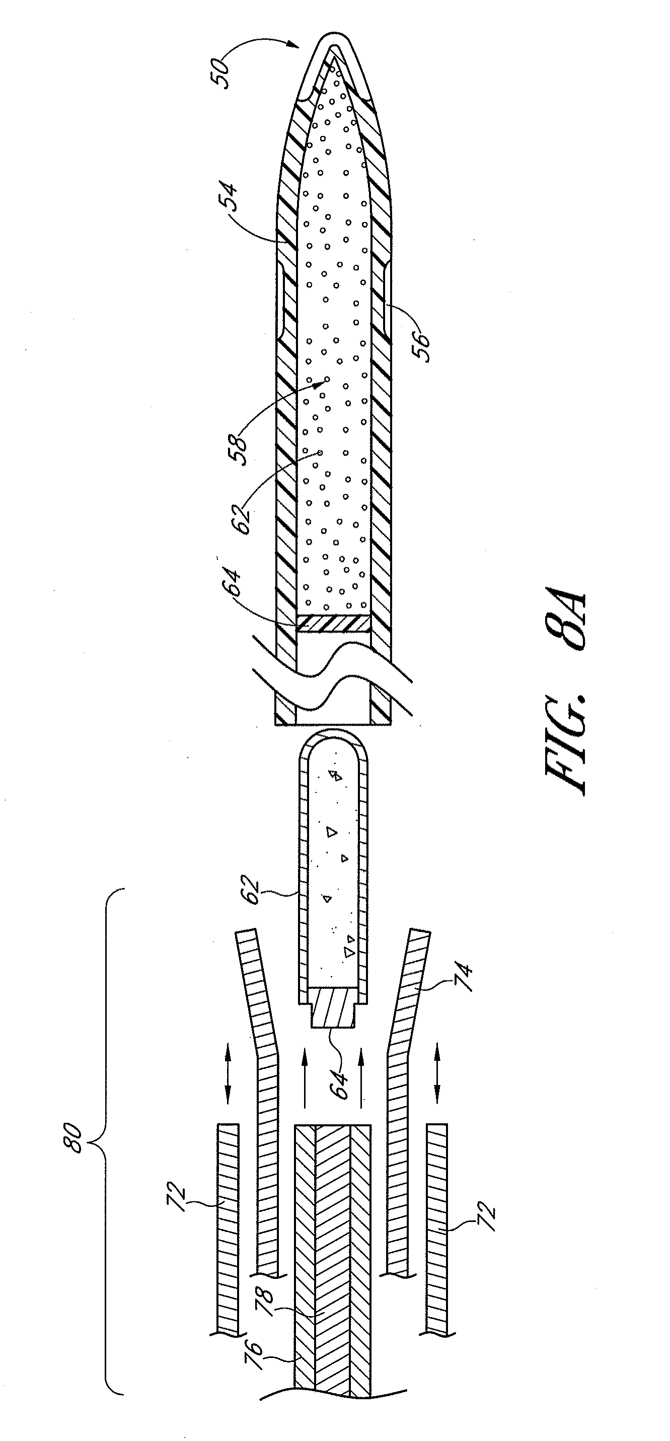
D00017

D00018

D00019
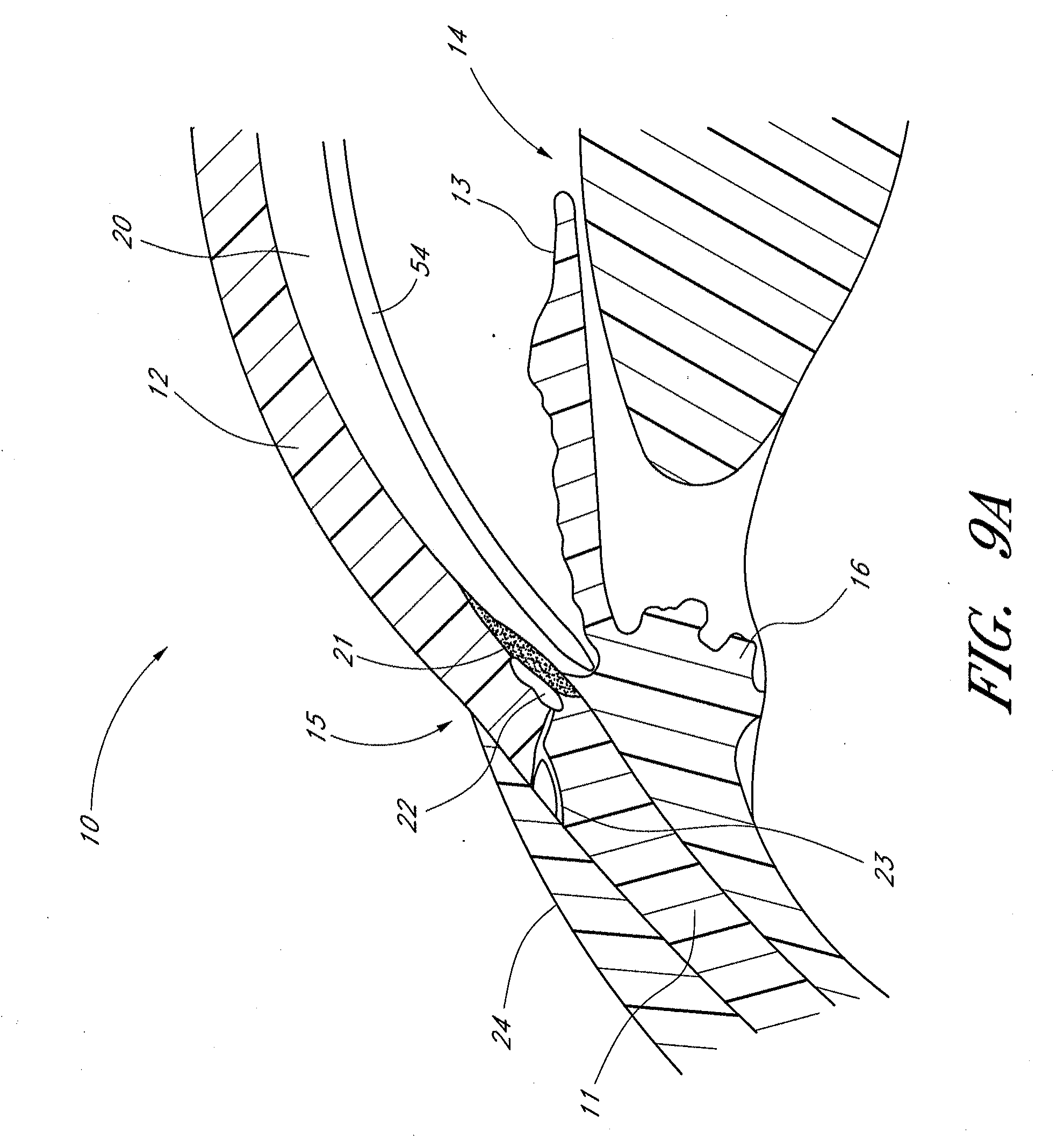
D00020

D00021

XML
uspto.report is an independent third-party trademark research tool that is not affiliated, endorsed, or sponsored by the United States Patent and Trademark Office (USPTO) or any other governmental organization. The information provided by uspto.report is based on publicly available data at the time of writing and is intended for informational purposes only.
While we strive to provide accurate and up-to-date information, we do not guarantee the accuracy, completeness, reliability, or suitability of the information displayed on this site. The use of this site is at your own risk. Any reliance you place on such information is therefore strictly at your own risk.
All official trademark data, including owner information, should be verified by visiting the official USPTO website at www.uspto.gov. This site is not intended to replace professional legal advice and should not be used as a substitute for consulting with a legal professional who is knowledgeable about trademark law.