Surgical Instrument With Lockout Mechanism
Shi; Stone ; et al.
U.S. patent application number 16/372918 was filed with the patent office on 2019-07-25 for surgical instrument with lockout mechanism. The applicant listed for this patent is Covidien LP. Invention is credited to Stone Shi, Shunhong Xu, Qianhong Yang.
| Application Number | 20190223866 16/372918 |
| Document ID | / |
| Family ID | 52103781 |
| Filed Date | 2019-07-25 |


View All Diagrams
| United States Patent Application | 20190223866 |
| Kind Code | A1 |
| Shi; Stone ; et al. | July 25, 2019 |
SURGICAL INSTRUMENT WITH LOCKOUT MECHANISM
Abstract
A surgical instrument comprising a handle assembly, an elongated portion, a head portion, an approximation mechanism, and a lockout mechanism is disclosed. The handle assembly comprises a movable handle and a stationary handle. The elongated portion extends distally from the handle assembly and defines a longitudinal axis. The head portion is disposed adjacent a distal portion of the elongated portion, and comprises a first jaw member and a second jaw member. The approximation mechanism comprises a drive member disposed in mechanical cooperation with the first jaw member and is configured to longitudinally move the first jaw member in relation to the second jaw member. The lockout mechanism is configured to selectively permit actuation of the movable handle to eject fasteners from the second jaw member. The lockout mechanism comprises a pin extending from the movable handle and is slidingly engaged with a slot in the drive member.
| Inventors: | Shi; Stone; (Jiangsu Province, CN) ; Yang; Qianhong; (Pudong Shanghai, CN) ; Xu; Shunhong; (Shanghai, CN) | ||||||||||
| Applicant: |
|
||||||||||
|---|---|---|---|---|---|---|---|---|---|---|---|
| Family ID: | 52103781 | ||||||||||
| Appl. No.: | 16/372918 | ||||||||||
| Filed: | April 2, 2019 |
Related U.S. Patent Documents
| Application Number | Filing Date | Patent Number | ||
|---|---|---|---|---|
| 14888162 | Oct 30, 2015 | 10271843 | ||
| PCT/CN2013/077331 | Jun 17, 2013 | |||
| 16372918 | ||||
| Current U.S. Class: | 1/1 |
| Current CPC Class: | A61B 17/1155 20130101; A61B 2017/00367 20130101; A61B 2017/00526 20130101; A61B 2090/0811 20160201; A61B 17/068 20130101 |
| International Class: | A61B 17/068 20060101 A61B017/068; A61B 17/115 20060101 A61B017/115 |
Claims
1. A method of adjusting a minimum gap between a cartridge assembly and an anvil assembly of a surgical instrument, the method comprising: rotating a handle assembly of the surgical instrument relative to an elongated portion of the surgical instrument such that the cartridge assembly moves along a longitudinal axis of the surgical instrument relative to the handle assembly, wherein a tissue contacting surface of the cartridge assembly and a tissue contacting surface of the anvil assembly define a tissue gap therebetween that varies in response to rotation of the handle assembly of the surgical instrument relative to the elongated portion of the instrument; and affixing the handle assembly to the elongated portion to prevent future movement therebetween.
2. The method according to claim 1, wherein rotating the handle assembly includes the elongated portion threadably engaging the handle assembly.
3. The method according to claim 1, further including rotating an approximation knob of the surgical instrument to cause longitudinal movement of a drive member of the surgical instrument and the anvil assembly relative to the cartridge assembly.
4. The method according to claim 3, further including rotating a stopper relative to the approximation knob until a blocking portion of the stopper contacts a proximal face of the drive member.
5. The method according to claim 4, further including affixing the stopper to the approximation knob to prevent future movement therebetween.
6. A method of selectively permitting actuation of a pivotable handle of a surgical instrument to eject fasteners, the method comprising: actuating an approximation mechanism of the surgical instrument to move a drive member of the surgical instrument and a first jaw member of the surgical instrument relative to a second jaw member of the surgical instrument; and moving a pin extending from the pivotable handle of the surgical instrument within a slot of the drive member from a blocking portion of the slot that fixes a position of the pivotable handle, to a firing portion of the slot that allows the pivotable handle to be actuated.
7. The method according to claim 6, wherein actuation of the approximation mechanism causes longitudinal translation of the slot relative to the pin.
8. The method according to claim 6, wherein moving the pin includes the pin disposed between the blocking portion and the firing portion of the slot when the first jaw member and the second jaw member are in an approximated position.
9. The method according to claim 8, further including actuating the pivotable handle when the pin is disposed between the blocking portion and the firing portion of the slot.
10. The method according to claim 6, further including threadably engaging a stopper with the approximation mechanism.
11. The method according to claim 11, further including rotating the stopper relative to the approximation mechanism until a blocking portion of the stopper contacts a proximal face of the drive member.
12. The method according to claim 11, further including affixing the stopper to the approximation mechanism to prevent future movement therebetween.
13. The method according to claim 6, wherein actuation of the approximation mechanism includes rotating an approximation knob of the approximation mechanism about a longitudinal axis defined by the drive member.
Description
CROSS-REFERENCE TO RELATED APPLICATIONS
[0001] This application is a divisional of U.S. patent application Ser. No. 14/888,162 filed Oct. 30, 2015, which is a National Stage Application of PCT/CN2013/077331, filed Jun. 17, 2013, under .sctn. 371 (a), the entire disclosure of which is incorporated by reference herein.
BACKGROUND
Technical Field
[0002] The present disclosure relates generally to a surgical fastening instrument for applying surgical fasteners to body tissue. More particularly, the present disclosure relates to a surgical fastening instrument that is locked out from firing fasteners until the cartridge assembly and anvil assembly are sufficiently approximated.
Background of Related Art
[0003] Anastomosis is the surgical joining of separate hollow organ sections. Typically, an anastomosis procedure follows surgery in which a diseased or defective section of hollow tissue is removed and the remaining end sections are to be joined. Depending on the desired anastomosis procedure, the end sections may be joined by either circular, end-to-end or side-to-side organ reconstruction methods.
[0004] In a circular anastomosis procedure, the two ends of the organ sections are joined by means of a stapling instrument which drives a circular array of staples or fasteners through the end section of each organ section and simultaneously cores any tissue interior of the driven circular array of staples to free the tubular passage. Examples of instruments for performing circular anastomosis of hollow organs are described for example in U.S. Pat. Nos. 7,303,106, 6,053,390, 5,588,579, 5,119,983, 5,005,749, 4,646,745, 4,576,167, and 4,473,077, each of which is incorporated herein in its entirety by reference. Typically, these instruments include an elongated shaft having a handle portion at a proximal end to actuate the instrument and a staple holding component disposed at a distal end. An anvil assembly including an anvil rod with an attached anvil head is mounted to the distal end of the instrument adjacent the staple holding component. Opposed end portions of tissue of the hollow organ(s) to be stapled are clamped between the anvil head and the staple holding component as these components are approximated. The clamped tissue is stapled by actuation of a trigger to drive one or more staples from the staple holding component so that the ends of the staples pass through the tissue and are deformed by the anvil head. An annular knife is concurrently advanced to core tissue within the hollow organ to free a tubular passage within the organ.
[0005] Besides anastomosis of hollow organs, surgical stapling instruments for performing circular anastomosis have been used to treat internal hemorrhoids in the rectum. Typically, during use of a circular stapling instrument for hemorrhoid treatment, the anvil head and the staple holding component of the surgical stapling instrument are inserted through the anus and into the rectum with the anvil head and the staple holding component in an open or unapproximated position. Thereafter, a pursestring suture is used to pull the internal hemorrhoidal tissue towards the anvil rod. Next, the anvil head and the staple holding component are approximated to clamp the hemorrhoid tissue between the anvil head and the staple holding component. The stapling instrument is fired to remove the hemorrhoidal tissue and staple the cut tissue. In stapled hemorrhoidopexy, a strip of mucosa and submucosa at the top of the hemorrhoids is removed by the stapling instrument, thereby treating the hemorrhoids by inhibiting blood flow to the tissue.
[0006] In certain situations, it is desirable to prevent premature firing of staples. Accordingly, it would be desirable for a surgical instrument to include a lockout mechanism that prevents the movable handle from being actuated until the anvil assembly and the cartridge assembly are sufficiently approximated.
SUMMARY
[0007] The present disclosure relates to a surgical instrument comprising a handle assembly, an elongated portion, a head portion, an approximation mechanism, and a lockout mechanism. The handle assembly comprises a movable handle and a stationary handle. The elongated portion extends distally from the handle assembly and defines a longitudinal axis. The head portion is disposed adjacent a distal portion of the elongated portion, and comprises a first jaw member and a second jaw member. The approximation mechanism comprises a drive member disposed in mechanical cooperation with the first jaw member and is configured to longitudinally move the first jaw member in relation to the second jaw member. The lockout mechanism is configured to selectively permit actuation of the movable handle to eject fasteners from the second jaw member. The lockout mechanism comprises a pin extending from the movable handle which is slidingly engaged with a slot in the drive member.
[0008] In disclosed embodiments, actuation of the approximation mechanism causes longitudinal translation of the slot with respect to the pin.
[0009] In disclosed embodiments, the slot in the drive member includes a blocking portion and a firing portion. When the pin is engaged with the blocking portion of the slot, the movable handle is prevented from being actuated, and when the pin is disposed between the blocking portion and the firing portion of the slot, the movable handle is able to be actuated. Here, it is disclosed that the pin is engaged between the blocking portion and the firing portion of the slot when the first jaw member and the second jaw member are in an approximated position. Here, it is disclosed that the pin is engaged with the firing portion of the slot during actuation of the movable handle. It is further disclosed that the firing portion of the slot is disposed distally adjacent the blocking portion of the slot. It is further disclosed that the blocking portion of the slot is substantially parallel to the longitudinal axis, and the firing portion of the slot is disposed at an angle with respect to the blocking portion of the slot. It is further disclosed that the firing portion of the slot is arcuate.
[0010] In disclosed embodiments, the surgical instrument further comprises an approximation knob disposed adjacent a proximal portion of the drive member, and a stopper threadably engaged with a portion of the approximation knob. A blocking portion of the stopper is configured to contact a proximal face of the drive member.
[0011] In disclosed embodiments, the handle assembly is threadably engaged with the elongated portion.
[0012] The present disclosure also relates to a method of adjusting the minimum tissue gap between a cartridge assembly and an anvil assembly of a surgical instrument. The method comprises providing a surgical instrument comprising a handle assembly, an elongated portion extending distally from the handle assembly and defining a longitudinal axis, a head portion disposed adjacent a distal portion of the elongated portion and comprising a cartridge assembly and an anvil assembly. A tissue-contacting surface of the cartridge assembly and a tissue-contacting surface of the anvil assembly define a tissue gap therebetween. The method also comprises rotating the handle assembly with respect to the elongated portion such that the cartridge assembly moves along the longitudinal axis with respect to the handle assembly, and affixing the handle assembly to the elongated portion to prevent future movement therebetween.
[0013] In disclosed embodiments, the elongated portion threadably engages the handle assembly.
[0014] In disclosed embodiments, the surgical instrument further comprises an approximation knob disposed in mechanical cooperation with the anvil assembly. Here, the method further comprises rotating the approximation knob to cause longitudinal movement of the anvil assembly with respect to the cartridge assembly. Here, it is disclosed that the surgical instrument further comprises a drive member disposed in mechanical cooperation with the approximation knob and in mechanical cooperation with the anvil assembly, such that rotation of the approximation knob causes longitudinal translation of the drive member and longitudinal translation of the anvil assembly. Here, it is disclosed that the surgical instrument further comprises a stopper threadably engaged with a portion of the approximation knob. It is further disclosed that the method comprises rotating the stopper with respect to the approximation knob until a blocking portion of the stopper contacts a proximal face of the drive member. It is further disclosed that the method comprises affixing the stopper to the approximation knob to prevent future movement therebetween.
DESCRIPTION OF THE DRAWINGS
[0015] Various embodiments of the presently disclosed surgical stapling instrument are disclosed herein with reference to the drawings, wherein:
[0016] FIGS. 1 and 2 are perspective views of the presently disclosed surgical instrument illustrated in an approximated position, in accordance with an embodiment of the present disclosure;
[0017] FIG. 3 is a side view of the surgical instrument of FIGS. 1 and 2;
[0018] FIG. 4 is a top view of the surgical instrument of FIGS. 1-3 after the surgical instrument has been fired;
[0019] FIG. 5 is an enlarged view of the area indicated in FIG. 4;
[0020] FIG. 6 is a perspective view of a distal end of the surgical instrument of the present disclosure including a shipping wedge thereon;
[0021] FIG. 7 is a perspective view of the shipping wedge of FIG. 6;
[0022] FIG. 8 is a perspective view of a portion of the surgical instrument of the present disclosure with various parts removed;
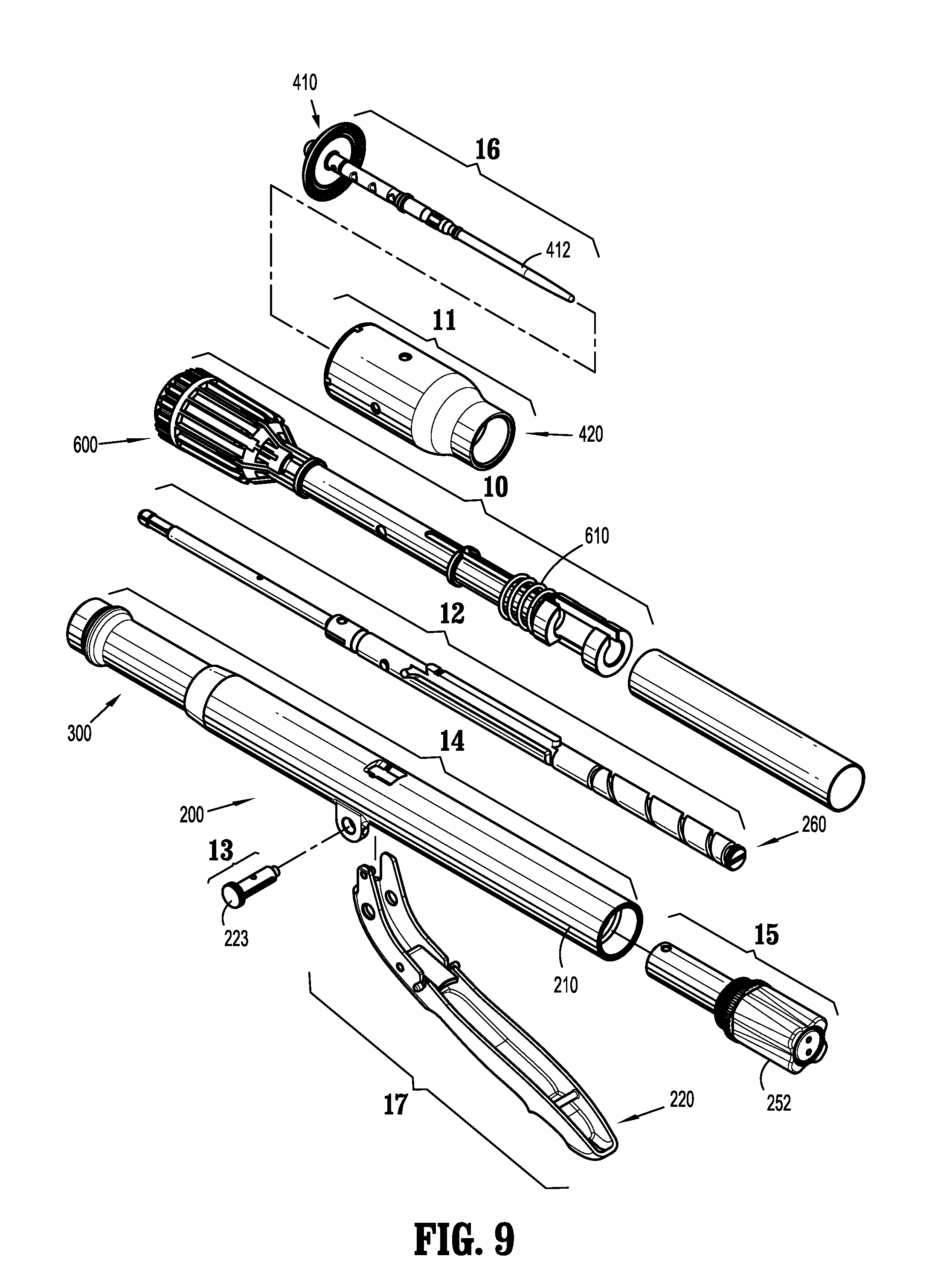
[0023] FIG. 9 is a perspective, assembly view of the surgical instrument of the present disclosure;
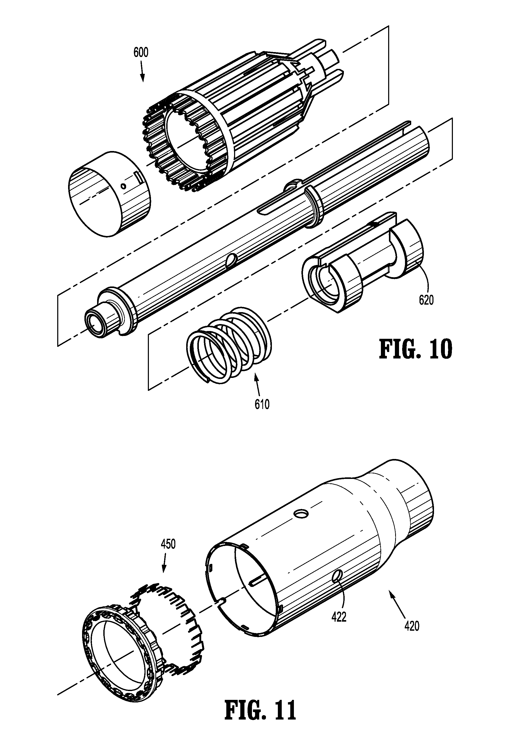
[0024] FIG. 10 is a perspective, assembly view of parts of an elongated portion of the surgical instrument of the present disclosure;
[0025] FIG. 11 is a perspective, assembly view of a shell assembly of the surgical instrument of the present disclosure;
[0026] FIG. 12 is a perspective, assembly view of a drive assembly of the surgical instrument of the present disclosure;
[0027] FIG. 13 is a perspective, assembly view of a pivot member of the surgical instrument of the present disclosure;
[0028] FIG. 14 is a perspective, assembly view of a portion of the handle assembly of the surgical instrument of the present disclosure;
[0029] FIG. 15 is a perspective, assembly view of an approximation mechanism of the surgical instrument of the present disclosure;
[0030] FIG. 16 is a perspective, assembly view of an anvil assembly of the surgical instrument of the present disclosure;
[0031] FIG. 17 is a perspective, assembly view of a movable handle of the surgical instrument of the present disclosure;
[0032] FIG. 18 is a perspective view of the surgical instrument of the present disclosure with various parts removed, and illustrating a firing assembly in a locked position;
[0033] FIG. 19 is an enlarged view of the area indicated in FIG. 18;
[0034] FIG. 20 is a cross-sectional view of the surgical instrument of the present disclosure taken along line 20-20 in FIG. 18;
[0035] FIG. 21 is an enlarged view of the area indicated in FIG. 20;
[0036] FIG. 22 is a cross-section view of the surgical instrument of the present disclosure taken along line 22-22 in FIG. 4;
[0037] FIG. 23 is a cross-section view of the surgical instrument of the present disclosure taken along line 23-23 in FIG. 22;
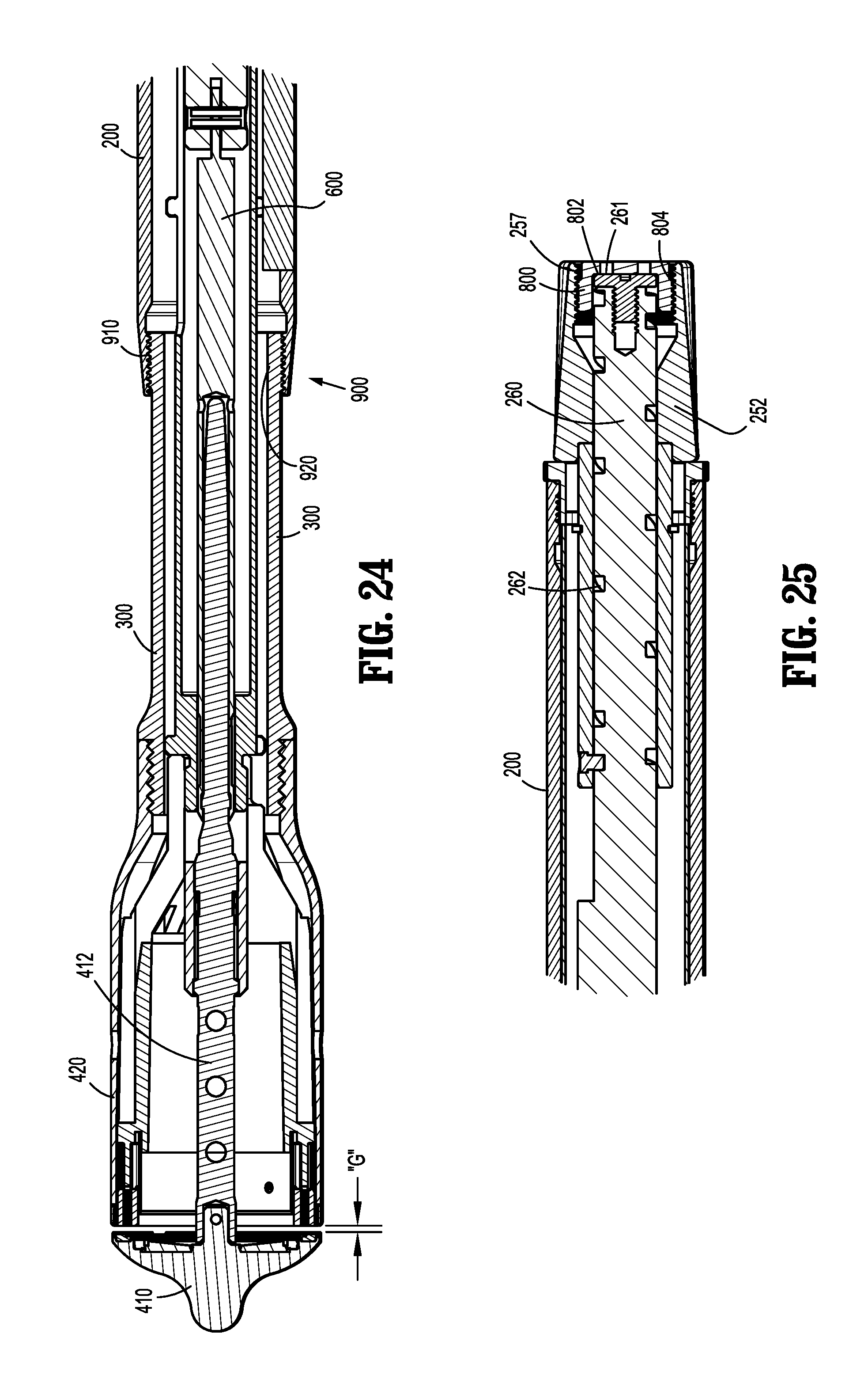
[0038] FIG. 24 is an enlarged view of the area indicated in FIG. 22;
[0039] FIG. 25 is an enlarged view of the area indicated in FIG. 22;
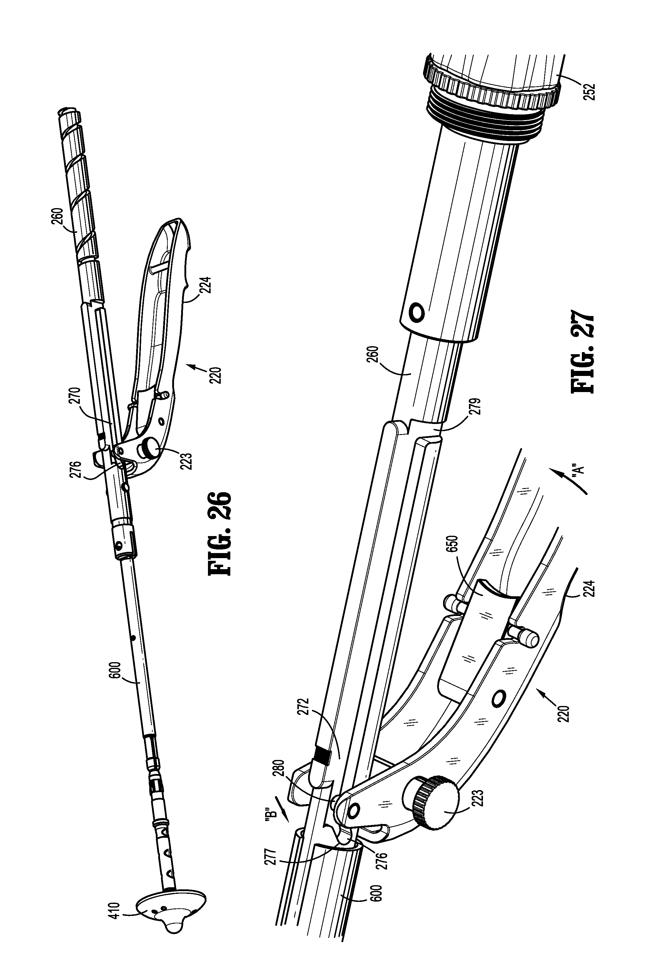
[0040] FIG. 26 is a perspective view of the surgical instrument of the present disclosure with various parts removed, and illustrating the firing assembly in a firing-enabled position;
[0041] FIG. 27 is an enlarged view of a portion of the surgical instrument illustrated in FIG. 26;
[0042] FIG. 28 is a proximal-looking transverse, cross-sectional view taken along line 28-28 in FIG. 22;
[0043] FIG. 29 is a transverse, cross-sectional view taken along line 29-29 in FIG. 22;
[0044] FIG. 30 is a proximal-looking transverse, cross-sectional view taken along line 30-30 in FIG. 22;
[0045] FIG. 31 is an enlarged view of the area indicated in FIG. 22 illustrating a safety latch in a firing-enabled position;
[0046] FIG. 32 illustrates the safety latch of FIG. 31 in a locked position;
[0047] FIG. 33 is a perspective view of the surgical instrument of the present disclosure with various parts removed, and illustrating the firing assembly in a firing-enabled position;
[0048] FIG. 34 is an enlarged view of the area indicated in FIG. 33;
[0049] FIG. 35 is a side view of portions of the surgical instrument of the present disclosure with various parts removed, and illustrating the firing assembly in a firing-enabled position; and
[0050] FIG. 36 is a side view of portions of the surgical instrument of the present disclosure with various parts removed, and illustrating the firing assembly in an actuated position.
DETAILED DESCRIPTION OF EMBODIMENTS
[0051] Embodiments of the presently disclosed surgical instrument will now be described in detail with reference to the drawings in which like reference numerals designate identical or corresponding elements in each of the several views. Throughout this description, the term "proximal" will refer to the portion of the instrument closer to the operator and the term "distal" will refer to the portion of the instrument farther from the operator.
[0052] FIGS. 1-36 illustrate an embodiment of the presently disclosed surgical instrument shown generally as 100. Briefly, surgical instrument 100 includes a handle assembly 200, an elongated body portion 300 defining a longitudinal axis X-X, a head portion 400, and a lockout mechanism 500. The length, shape, curvature and/or diameter of elongated body portion 300 and head portion 400 may be varied to suit a particular surgical procedure.
[0053] With specific reference to FIGS. 1-4, handle assembly 200 includes a stationary handle 210, a movable handle 220, and an approximation mechanism 250. Head portion 400 includes a first jaw member (i.e., an anvil assembly 410) and a second jaw member (i.e., a shell assembly 420). Anvil assembly 410 is movable in relation to shell assembly 420 between spaced (e.g., FIGS. 18 and 20) and approximated positions (e.g., FIGS. 1, 2 and 22).
[0054] With reference to FIGS. 9, 12, 15 and 18, further details of approximation mechanism 250 are disclosed. Approximation mechanism 250 includes an approximation knob 252 and a drive member or drive screw 260. Approximation knob 252 is mechanically engaged with drive screw 260, and a distal portion 262 of drive screw 260 is configured to mechanically engage an anvil retainer 412 (FIG. 16). The proximal potion of drive screw 260 includes a helical channel 262 and is slidably positioned within a central bore 253 of a rotatable sleeve 254 (FIG. 15), which extends distally from approximation knob 252. A pin 256 extends through a hole 255 in a distal portion of sleeve 254 into helical channel 264. Sleeve 254 is axially fixed with respect to stationary handle 210. Thus, rotation of approximation knob 252 causes rotation of sleeve 254, which causes pin 256 to move along channel 262 of drive screw 260 to effect axial movement of drive screw 260, and thus a corresponding axial movement of anvil retainer 412 and anvil assembly 410. That is, rotation of approximation knob 252 causes movement of anvil assembly 410 in relation to shell assembly 420 between spaced and approximated positions, More particularly, rotation of approximation knob 252 in a first direction (e.g., clockwise) retracts anvil retainer 412 to cause proximal movement of anvil assembly 410 (i.e., toward shell assembly 420). Rotation of approximation knob 252 in a second opposite direction (e.g., counter-clockwise) distally advances anvil retainer 412 to cause distal movement of anvil assembly 410 (i.e., away from shell assembly 420). Other approximation mechanisms are also contemplated. Further details of the approximation mechanism are described in U.S. Pat. No. 7,303,106, the entire contents of which are incorporated herein by reference.
[0055] Referring now to FIGS. 35 and 36, actuation of movable handle 220 (i.e., pivoting in the direction of arrow "A" in FIG. 36), from its firing enabled position (FIG. 35) to its actuated or fired position (FIG. 36), causes fasteners or staples 450 (FIG. 11) to be ejected from shell assembly 420 toward anvil assembly 410. That is, movable handle 220 is disposed in mechanical cooperation with a pusher 600, such that actuation of movable handle 220 causes distal advancement of pusher 600 into direct or indirect contact with staples 450, which causes ejection of staples 450 toward staple deforming pockets 411 (FIG. 16) of anvil assembly 410. More particularly, a biasing element 610 urges pusher 600 proximally into contact with a camming surface 222 of movable handle 220. A distal portion of biasing element 610 is in contact with a wall 202 (FIG. 22) extending radially inwardly from an inner wall 204 of handle assembly 200, thus enabling biasing element 610 to proximally bias pusher 600. When movable handle 220 is actuated, i.e. pivoted about a pivot member 223, camming surface 222 of movable handle 220 is moved distally, camming a proximal portion of pusher 600, which causes distal translation of pusher 600 and ejection of staples 450. Further details of the actuation of the movable handle to cause ejection of staples is described in U.S. Pat. No. 7,303,106, incorporated by reference herein in its entirety.
[0056] Referring now to FIGS. 12, 18, 19, 26, 27 and 33-36, lockout mechanism 500 of surgical instrument 100 is shown. Locking mechanism 500 is configured to prevent premature ejection of staples from shell assembly 420. Moreover, locking mechanism 500 prevents actuation of movable handle 220 until anvil assembly 410 has been moved into its approximated position with respect to shell assembly 420. Locking mechanism 500 includes a slot 270 in drive screw 260, and a pin 280 extending from a portion of movable handle 220 and which engages slot 270. With specific reference to FIG. 12, slot 270 includes a first, blocking portion 272, and a second, firing portion 276.
[0057] With specific reference to FIG. 19, prior to sufficient approximation of anvil assembly 410, pin 280 of movable handle is within blocking portion 272 of slot 270. In this position, a user is prevented from actuating movable handle 220 in the direction of arrow "A," because an attempt to do so would cause pin 280 to move in the direction of arrow "B" (FIG. 19). As shown, pin 280 is unable to move in the direction of arrow "B" because pin 280 would be forced against a lower wall 273 of blocking portion 272 of slot 270, thus preventing actuation of movable handle 220.
[0058] Referring now to FIG. 27, after sufficient approximation of anvil assembly 410, pin 280 of movable handle 220 is adjacent firing portion 276 of slot 270. That is, drive screw 260 has been distally advanced via rotation of approximation knob 252 such that firing portion 276 of slot 270 of drive screw 260 is adjacent pin 280 of movable handle 220. In this position, actuation of movable handle 220 by a user causes a gripping portion 224 of movable handle 220 to move in the direction of arrow "A" and causes pin 280 of movable handle 220 to move in the direction of arrow "B" into firing portion 276 of slot 270. As discussed above, when pin 280 of movable handle 220 moves into firing portion 276 of slot 270, camming surface 222 of movable handle 220 is moved distally, camming a proximal portion of pusher 600, which causes distal translation of pusher 600 and ejection of staples 450.
[0059] Additionally, when pin 280 of movable handle 220 is within firing portion 276 of slot 270, drive screw 260 is physically prevented from longitudinal movement. That is, in this position, a user will be prevented from rotating approximation knob 252, as the engagement between pin 280 and firing portion 276 of slot 270 of drive screw 260 would prevent longitudinal movement of drive screw 260. More particularly, the engagement between pin 280 and a distal wall 277 of firing portion 276 of slot 270 would prevent drive screw 260, and thus anvil assembly 410, from proximally translating (see also FIGS. 35 and 36). The engagement between pin 280 and a proximal wall 278 of firing portion 276 of slot 270 would prevent drive screw 260, and thus anvil assembly 410, from distally translating.
[0060] After movable handle 220 is actuated to effect firing and the user releases the force against movable handle 220, biasing element 610 urges pusher 600 and thus camming surface 222 of movable handle 220 proximally. Pin 280 is likewise moved proximally out of firing portion 276 of slot 270, thus enabling longitudinal translation of drive screw 260.
[0061] Additionally, slot 270 includes a transverse portion 279 disposed at the proximal-most end of slot 270 (FIG. 27). It is envisioned that transverse portion 279 of slot 270 facilitates assembly of surgical instrument 100. That is, during assembly, pin 280 of movable handle 220 is able to enter slot 270 through transverse portion 279.
[0062] In the illustrated embodiments, and with particular reference to FIGS. 31 and 32, surgical instrument includes a safety latch 650 disposed in mechanical cooperation with movable handle 220. Safety latch 650 is another feature of surgical instrument 100 that is configured to maintain movable handle 220 in an open, non-actuated position until anvil assembly 410 and shell assembly 420 have been approximated. When safety latch 650 is in the blocking position shown in FIG. 32 (wherein anvil assembly 410 and shell assembly 420 are in an unapproximated (spaced) position), movable handle 220 cannot be squeezed or actuated. When safety latch 650 is in the enabling position shown in FIG. 31 (wherein anvil assembly 410 and shell assembly 420 are in a closed position), movable handle 220 is able to be actuated. It is envisioned that safety latch 650 is biased into its blocking position (FIG. 32), and is movable by a user into its enabling position (FIG. 31). As can be appreciated, safety latch 650 is an additional feature that may be included to help prevent staples from being fired prematurely by physically blocking movement of movable handle 220.
[0063] As shown in FIGS. 8 and 10, pusher 600 includes a proximal extension 620. An outer perimeter of at least part of proximal extension 620 contacts an inner wall 204 of handle assembly 200 (see FIGS. 22 and 31). It is envisioned that proximal extension 620 of pusher 600 helps balance the forces enacted on drive screw 260 during firing of surgical instrument 100. That is, the friction between inner wall 204 of handle assembly 200 and proximal extension 620 during longitudinal translation of drive screw 260 helps prevent drive screw 260 from twisting or torquing during firing.
[0064] With particular reference to FIGS. 5 and 34, surgical instrument 100 includes an indicator 700. Indicator 700 includes a first indicia 710 disposed adjacent a distal portion of drive screw 260, a second indicia 720 disposed adjacent proximal extension 620 of pusher 600, and a window 730 on handle assembly 200. Indicator 700 is configured to enable a user determine whether staples 450 have been fired from shell assembly 420. A user knows when staples 450 have been fired, when, as viewed through window 730, first indicia 710 is longitudinally aligned with second indicia 720. In FIG. 34, where first indicia 710 and second indicia 720 are longitudinally displaced from each other, movable handle 220 has not yet been actuated and thus no staples have been fired. In FIG. 5, first indicia 710 and second indicia 720 are longitudinally aligned, and thus indicates that surgical instrument 100 has been fired.
[0065] With reference to FIGS. 21 and 25, a stopper 800 is illustrated. Stopper 800 is threadably engaged with approximation knob 252 and is configured to ensure the position of drive screw 260 with respect to pin 280 of movable handle 220. During assembly, approximation knob 252 is rotated a sufficient amount that corresponds to firing position 276 of slot 270 being adjacent pin 280. Once this position is confirmed, stopper 800 is rotated (e.g., advanced distally) until a blocking portion 802 stopper 800 makes contact with a proximal face 261 of drive screw 260 (FIG. 25). Next, during assembly, welding or a thread adhesive, for example, is used where the threads 804 of stopper 800 engage threads 257 of approximation knob 252 to prevent future longitudinal movement of stopper 800 with respect to approximation knob 252. When stopper 800 is in this position and effectively affixed to approximation knob 252, the proper positioning of drive screw 260 (e.g., firing portion 276 of slot 270 therein) with respect to pin 280 is ensured.
[0066] Referring now to FIG. 24, surgical instrument 100 includes a tissue gap adjustment mechanism 900. Tissue gap adjustment mechanism 900 enables altering the gap "G" between tissue-contacting surfaces of anvil assembly 410 and shell assembly 420 after assembly of surgical instrument 100. Due in part to the build up of manufacturing tolerances, it is often cost prohibitive to achieve an exact or precise tissue gap "G" in an assembled surgical instrument. In the present disclosure, an exact tissue gap "G" can be achieved without the use of tighter or more strict manufacturing tolerances.
[0067] Tissue gap adjustment mechanism 900 includes a first threaded portion 910 disposed adjacent a distal portion of handle assembly 200, and a second threaded portion 920 disposed adjacent a proximal portion of elongated body portion 300. First threaded portion 910 is configured to threadably engage second threaded portion 920. After at least a partial assembly of surgical instrument 100, handle assembly 200 is rotated with respect to elongated body portion 300 to increase or decrease the size of the tissue gap "G" by advancing or retracting shell assembly 420. That is, when handle assembly 200 is rotated in a first direction about the longitudinal axis X-X with respect to elongated body portion 300, shell assembly 420 moves proximally with respect to handle assembly 200 and the tissue gap "G" increases, and when handle assembly 200 is rotated in a second direction about the longitudinal axis X-X with respect to elongated body portion 300, shell assembly 420 moves distally with respect to handle assembly 200 and the tissue gap "G" decreases. Once the desired tissue gap "G" is achieved, welding or a thread adhesive, for example, is used where first threaded portion 910 and second threaded portion 920 are engaged to prevent future longitudinal movement between handle assembly 200 and elongated body portion 300. As can be appreciated, the location of tissue gap adjustment mechanism 900 (i.e., where handle assembly 200 and elongated body portion 300 meet) is not limited to the location shown in the figures, but can be disposed in any reasonable location on surgical instrument 100.
[0068] FIGS. 6 and 7 illustrate a shipping wedge 950. Shipping wedge 950 includes a first pair of tines 952 and a second pair of tines 954. Tines 952 are configured to slidingly engage apertures 414 (FIG. 16) on a distal end of anvil assembly 410. Tines 954 are radially-outwardly flexible and are configured to releasably engage openings 422 (FIG. 11) on an outer wall of shell assembly 420. It is envisioned that shipping wedge 950 maintains anvil assembly 410 in a substantially fixed longitudinal position with respect to shell assembly 420 during shipping, storage, etc. of surgical instrument 100.
[0069] The present disclosure also relates to a method of performing a surgical procedure using surgical instrument 100 described herein, a method of manufacturing surgical instrument 100 described herein, a method of assembling surgical instrument 100 described herein, and a method of adjusting tissue gap "G" as described herein.
[0070] It will be understood that various modifications may be made to the embodiments disclosed herein. Therefore, the above description should not be construed as limiting, but merely as exemplifications of disclosed embodiments. Those skilled in the art will envision other modifications within the scope and spirit of the claims appended hereto.
* * * * *
D00000
D00001
D00002
D00003
D00004
D00005
D00006
D00007
D00008
D00009
D00010
D00011
D00012

D00013
D00014
D00015

D00016

D00017

XML
uspto.report is an independent third-party trademark research tool that is not affiliated, endorsed, or sponsored by the United States Patent and Trademark Office (USPTO) or any other governmental organization. The information provided by uspto.report is based on publicly available data at the time of writing and is intended for informational purposes only.
While we strive to provide accurate and up-to-date information, we do not guarantee the accuracy, completeness, reliability, or suitability of the information displayed on this site. The use of this site is at your own risk. Any reliance you place on such information is therefore strictly at your own risk.
All official trademark data, including owner information, should be verified by visiting the official USPTO website at www.uspto.gov. This site is not intended to replace professional legal advice and should not be used as a substitute for consulting with a legal professional who is knowledgeable about trademark law.