Gripping Glove
George; Robert
U.S. patent application number 15/879349 was filed with the patent office on 2019-07-25 for gripping glove. The applicant listed for this patent is Robert George. Invention is credited to Robert George.
| Application Number | 20190223527 15/879349 |
| Document ID | / |
| Family ID | 67297997 |
| Filed Date | 2019-07-25 |


| United States Patent Application | 20190223527 |
| Kind Code | A1 |
| George; Robert | July 25, 2019 |
GRIPPING GLOVE
Abstract
The present invention relates to a gripping glove with a gripping attachment disposed on the palm of the glove. To provide flexibility and friction enhancement, the gripping attachment can be a natural or synthetic polymer having elastic properties, such as rubber. The gripping attachment is structured and arranged to wrap at least partly around an elongated object when the elongated object is grasped. The elongated object can be a piece of sports equipment, such as a golf club or a handle of a racquet or a paddle, a handle of a tool such as a hammer, a chisel, or a file, etc.
| Inventors: | George; Robert; (San Jose, CA) | ||||||||||
| Applicant: |
|
||||||||||
|---|---|---|---|---|---|---|---|---|---|---|---|
| Family ID: | 67297997 | ||||||||||
| Appl. No.: | 15/879349 | ||||||||||
| Filed: | January 24, 2018 |
| Current U.S. Class: | 1/1 |
| Current CPC Class: | A63B 71/146 20130101; A63B 71/141 20130101; A41D 19/01547 20130101; A63B 2102/02 20151001; A41D 19/01558 20130101; A63B 71/148 20130101; A63B 2209/10 20130101; A63B 69/3608 20130101; A63B 2102/32 20151001; A63B 69/38 20130101; A41D 19/0037 20130101; A63B 2102/065 20151001 |
| International Class: | A41D 19/015 20060101 A41D019/015; A63B 71/14 20060101 A63B071/14; A41D 19/00 20060101 A41D019/00 |
Claims
1. A gripping glove, comprising: a glove; and a gripping attachment disposed on the palm of the glove; wherein the gripping attachment is structured and arranged to wrap at least partly around an elongated object when the elongated object is grasped by the gripping glove.
2. The gripping glove of claim 1, wherein the gripping attachment is made of an elastomer.
3. The gripping glove of claim 1, wherein the elongated object is sports equipment.
4. The gripping glove of claim 3, wherein the sports equipment is a golf club.
5. The gripping glove of claim 3, wherein the sports equipment is a racquet or a paddle.
6. The gripping glove of claim 1, wherein the gripping attachment includes a middle area with a roughly planer surface surrounded on two opposite sides by ridges.
7. The gripping glove of claim 6, wherein the ridges include concave structures facing the middle area.
8. The gripping glove of claim 6, wherein the gripping attachment includes a plurality of extension pieces.
9. The gripping glove of claim 8, wherein the plurality of extension pieces extend to finger coverings of the glove.
10. The gripping glove of claim 9, wherein the extension pieces extend to the glove's index finger, middle finger, and ring finger coverings.
11. The gripping glove of claim 1, wherein the gripping attachment includes a middle area with a roughly planer surface surrounded on two opposite sides by a first ridge and a second ridge, respectively; wherein the first ridge is continuous, and the second ridge is discontinuous and includes extension pieces extending onto fingers of the glove.
11. The gripping glove of claim 11, wherein the extension pieces extend onto the glove's index finger, middle finger, and ring finger coverings.
12. The gripping glove of claim 1, wherein the grip attachment is sewn onto the glove.
13. The gripping glove of claim 1, wherein the grip attachment is bonded to the glove.
14. The gripping glove of claim 1, wherein the grip attachment is made integral with the glove without using an attachment mechanism.
15. The gripping glove of claim 1, wherein the gripping attachment includes concave structures that conform to the curvature of the outer surface of the elongated object.
Description
BACKGROUND OF THE INVENTION
1. Field of the Invention
[0001] The present invention relates to a glove with an attachment for ensuring a proper grip of an elongated object.
2. Description of the Related Art
[0002] In many cases, it is important to hold an elongated object such as a piece of sports equipment properly to obtain a desired effect or outcome. As an example, in golf, the golfer must carefully grasp the golf club to ensure that the club head hits the ball in such a way that the ball reaches the intended target. A common problem is that the club handle is either held too tightly or loosely, or at the wrong angle. Similarly, in other sports, such as racquetball and tennis, holding the handle of the racquet or paddle properly is critical. Additionally, there are many other endeavors where proper form is important when gripping an elongated object.
[0003] Traditionally, various types of gloves are available to be worn to address grip and comfort. In golf, for example, players sometimes wear a thin leather golf glove. Similarly, baseball and tennis players are sometimes seen wearing gloves, as are construction workers and artisans who work with various tools. Although such gloves can be better suited than one's own bare hands, they do not improve technique or form.
SUMMARY OF THE INVENTION
[0004] One aspect of the disclosure relates to a gripping glove with a gripping attachment disposed on the palm of the glove. To provide flexibility and friction enhancement, the gripping attachment can be a natural or synthetic polymer having elastic properties, such as rubber. The gripping attachment is structured and arranged to wrap at least partly around an elongated object when the elongated object is grasped. The elongated object can be a piece of sports equipment, such as a golf club or a handle of a racquet or a paddle. In other embodiments, the elongated object can be the handle of a tool such as a hammer, a chisel, or a file. In other embodiments, the elongated object can be the handle of a vehicle such as a motorcycle or bicycle. In still other embodiments, the elongated object can be another type of object other than these examples.
[0005] In an embodiment, the gripping attachment can be sewn, stapled, or bonded to the glove using an adhesive or the like. In other embodiments, the gripping attachment is removable from the glove, e.g., using a hook-and-loop fastener. It still other embodiments, the gripping attachment is integral with the glove without using an attachment mechanism. For example, the glove and the glove attachment could be molded together, or printed using a 3D printer (using the same or different materials for the component parts).
[0006] In an embodiment, the gripping attachment includes a roughly flat middle area surrounded on two opposite sides by elevated structures (ridges). In an embodiment, the ridges curve upwardly on sides facing the middle area forming concave structures on those sides. Additionally, the gripping attachment can include a plurality of extension pieces that extend onto portions of a plurality of respective finger coverings of the glove. In an embodiment, the gripping attachment includes a first ridge and a second ridge, wherein the first ridge is continuous, and the second ridge is discontinuous and includes extension piece extending onto several of the glove's finger coverings.
BRIEF DESCRIPTION OF THE DRAWINGS
[0007] FIG. 1 is a perspective view of an exemplary glove with a gripping attachment, according to an embodiment.
[0008] FIG. 2 illustrates the gripping attachment itself, according to an embodiment.
[0009] FIG. 3 illustrates a fitting of the exemplary glove with gripping attachment, according to an embodiment.
[0010] FIG. 4 illustrates usage of the exemplary glove with gripping attachment, according to an embodiment.
[0011] FIG. 5 is a top view of the gripping attachment, according to an embodiment.
[0012] FIG. 6 is a bottom view of a portion of the gripping attachment, according to an embodiment.
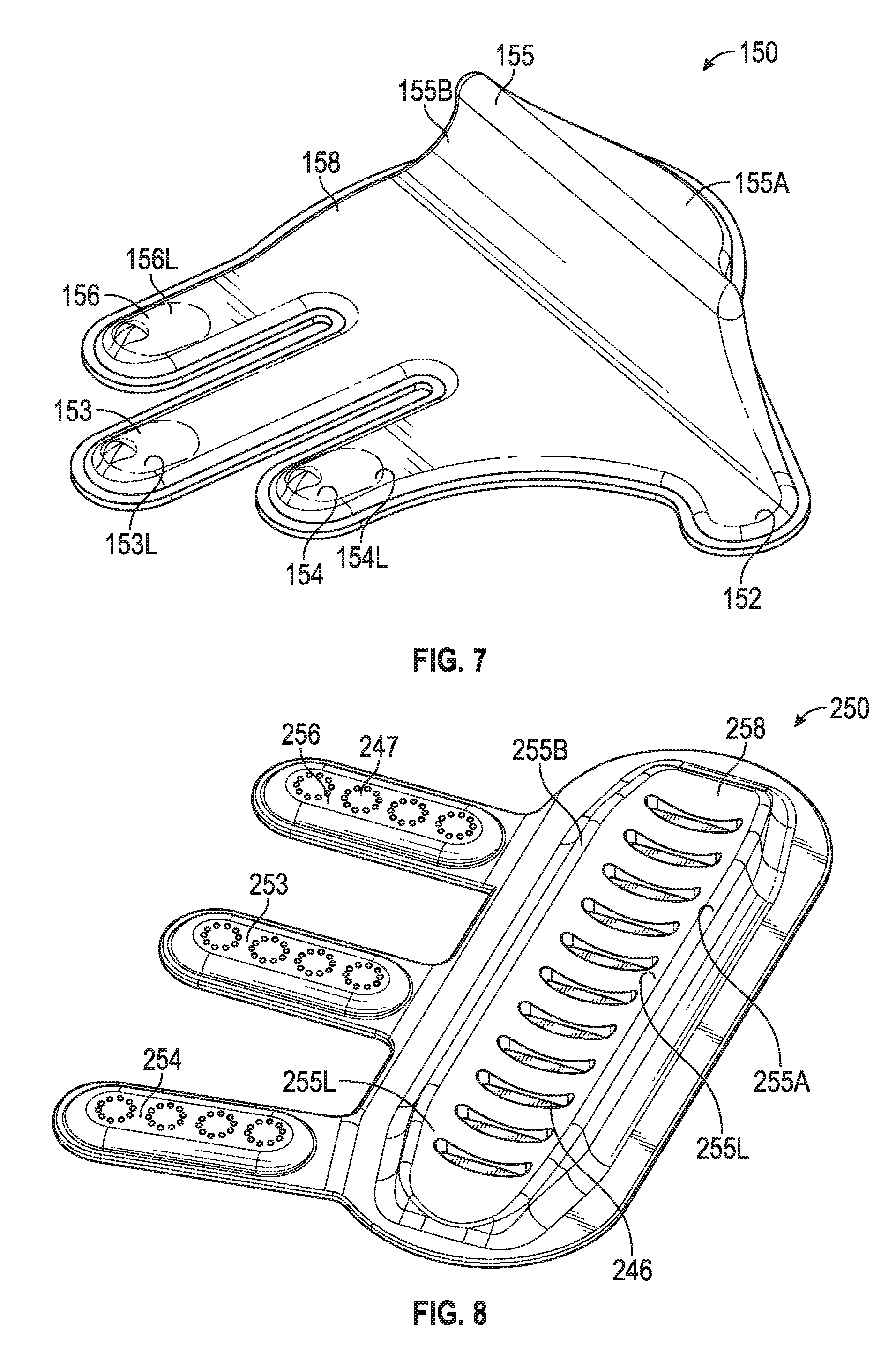
[0013] FIG. 7 illustrates a gripping attachment, according to another embodiment.
[0014] FIG. 8 illustrates a gripping attachment, according to yet another embodiment.
[0015] FIG. 9 illustrates an exemplary glove with the gripping attachment of FIG. 8 attached thereto.
DETAILED DESCRIPTION OF THE INVENTION
[0016] Referring to FIG. 1, an exemplary gripping glove 100, according to an embodiment, is illustrated. As shown, the gripping glove 100 includes a gripping attachment 50 that is attached to the palm of a glove 80 using stitching 51. To provide flexibility and friction enhancement, the gripping attachment 50 can be an elastomer such as a natural or synthetic polymer having elastic properties, such as rubber. In an embodiment, the gripping attachment 50 can be sewn (such as is illustrated), stapled, bonded, or otherwise permanently fastened to the glove 80. In other embodiments, the gripping attachment 50 is removably attached to the glove 80, e.g., using a hook-and-loop fastener. It still other embodiments, the gripping attachment 50 is integral with the glove 80 without an attachment mechanism. For example, the glove 80 and the gripping attachment 50 could be formed in the same mold or printed together using a 3D printer.
[0017] Referring to FIG. 2, the exemplary gripping attachment 50 is illustrated. The gripping attachment 50 includes a roughly flat middle area 58 (valley) surrounded on opposite sides by two elevated structures (ridges), i.e., ridge 55 on one side and ridges 53 and 54 on the other side. In the illustrated embodiment, the first ridge 55 is continuous and the second ridge (comprising the ridges 53 and 54) is discontinuous. In the illustrated embodiment, the glove 80 is a 5-finger glove that covers the entire hand and individually the fingers (including index finger 112, middle finger 113, ring finger 114, pinkie 115, and thumb 116). However, in other embodiments, the glove 80 does not entirely cover each of the fingers 112-116 individually. In the shown embodiment, the ridges 53-54 and 55 curve upwardly on sides facing the middle area 58 forming concave structures 53L, 54L, and 55B, respectively. At the top of ridges 53 and 54 are substantially flat portions 53M and 54M, respectively. At the back end of ridge 55 is a downwardly sloping portion 55A. Notably, the gripping attachment 50 includes a plurality of extension pieces (see FIG. 1) that extend onto portions of a plurality of respective finger coverings of the glove. In an embodiment, the extension pieces extend to part of the glove's index finger 112, middle finger 113, and ring finger 114 coverings. In the shown embodiment, the extension pieces are the ridges 53 and 54, and an extension piece 52 which is part of the middle area 58.
[0018] Referring to FIG. 3, a fitting of the exemplary glove with gripping attachment 100, according to an embodiment, is illustrated. Advantageously, the gripping attachment 50 is structured and arranged to wrap at least partly around an elongated object when the elongated object is grasped. As shown, the glove 80 is a golf glove and the elongated object 90 being fitted into the gripping attachment 50 is a golf club. As shown, the elongated object 90 (golf club) is placed into the middle area 58.
[0019] FIG. 4 illustrates usage of the exemplary glove with gripping attachment 100. As the user closes his or her hand, the gripping attachment 50 closes at least partly around the elongated object 90 (golf club). More particularly, the concave structures 53L, 54L, and 55B conform to the curvature of the outer surface of the elongated object (golf club 90), causing a tight grip. Notably, because the gripping attachment 50 will preferably be aligned at an angle suitable for a golf hand posture, the result will be an improved grip. Moreover, as the golfer repeatedly uses the device 100, the proper golf club grip should be imprinted into the golfer's long-term memory ("muscle memory").
[0020] FIG. 5 is a top view of the gripping attachment 50, according to an embodiment.
[0021] FIG. 6 is a bottom view of a portion of the gripping attachment 50, according to an embodiment. As shown, the bottom portion 55L of the ridge 55 includes a plurality of supports 56 that provide structural integrity to the ridge 55 to ensure that this section of the gripping attachment 50 is sturdy. These supports can be formed in a suitable mold used during the fabrication process.
[0022] In accordance with various embodiments of the present invention, the elongated object held by the gripping glove can be a piece of sports equipment, such as a golf club (as illustrated above) or a handle of a racquet or a paddle. In other embodiments, the elongated object can be the handle of a tool such as a hammer, a chisel, or a file. In still other embodiments, the elongated object can be the handle of a motorcycle or bicycle. In still other embodiments, the elongated object can be some other object. Notably, the structure of the gripping attachment and its orientation on the glove can vary depending on the object and usage of the gripping device.
[0023] FIG. 7 illustrates a gripping attachment 150, according to another embodiment. The gripping attachment 150 can be attached to a suitable glove (not shown) and used for gripping the handlebars of a motorcycle or the like. The gripping attachment 150 is similar to the gripping attachment 50 discussed above except most notably the gripping attachment 150 includes an extra extension piece and the gripping attachment 150 would be arranged on a glove differently such that the gripping attachment 150 conforms to the handlebar when the driver grasps the handlebar during operation of the vehicle. As shown, the gripping attachment 150 includes a roughly fiat middle area 158 (valley) surrounded on opposite sides by two elevated structures (ridges), i.e., ridge 155 on one side and ridges 153, 154 and 156 on the other side. In the illustrated embodiment, the first ridge 155 is continuous and the second ridge (comprising ridges 153, 154 and 156) is discontinuous. In the shown embodiment, the ridges curve upwardly on sides facing the middle area 158 forming concave structures 153L, 154L, 156L and 155B, respectively. At the back end of ridge 155 is a downwardly sloping portion 155A. Notably, the gripping attachment 150 includes a plurality of extension pieces that extend onto portions of a plurality of respective finger coverings of a glove (not shown). The extension pieces are the ridges 154, 153 and 156 and an extension piece 52 (which is part of the middle area 158), extending to glove finger coverings for the index finger, middle finger, pinkie, and thumb, respectively.
[0024] FIG. 8 illustrates a gripping attachment 250, according to yet another embodiment. FIG. 9 illustrates a glove 280 with the gripping attachment 250 attached thereto. The gripping attachment 250 can be used for gripping the handle 290 of a hammer 295 or the like. As shown, the gripping attachment 250 includes a roughly flat middle area 258 (valley) surrounded on opposite sides by two elevated structures (ridges), i.e., ridge 255A on one side and ridge 25513 on the other side. In the illustrated embodiment, the ridges 255A and 255B are continuous. In the shown embodiment, the ridges curve upwardly on sides facing the middle area 258 forming concave structures 255L. Notably, the gripping attachment 150 includes a plurality of extension pieces 254, 253, and 256 that extend onto portions of a plurality of respective finger coverings of the glove 280. The extension pieces 254, 253, and 256 can include extension piece friction enhancers 247, which can include raised bumps or the like to increase friction with the handle 290. Additionally, friction enhancers 246 can be included in the middle area 258 or elsewhere. Such friction enhancers 246 can include indentations (as shown) or raised bumps, etc.
[0025] While this invention has been described in conjunction with the various exemplary embodiments outlined above, it is evident that many alternatives, modifications and variations will be apparent to those skilled in the art. Accordingly, the exemplary embodiments of the invention, as set forth above, are intended to be illustrative, not limiting. Various changes may be made without departing from the spirit and scope of the invention.
* * * * *
D00000
D00001
D00002
D00003
D00004
D00005
D00006
XML
uspto.report is an independent third-party trademark research tool that is not affiliated, endorsed, or sponsored by the United States Patent and Trademark Office (USPTO) or any other governmental organization. The information provided by uspto.report is based on publicly available data at the time of writing and is intended for informational purposes only.
While we strive to provide accurate and up-to-date information, we do not guarantee the accuracy, completeness, reliability, or suitability of the information displayed on this site. The use of this site is at your own risk. Any reliance you place on such information is therefore strictly at your own risk.
All official trademark data, including owner information, should be verified by visiting the official USPTO website at www.uspto.gov. This site is not intended to replace professional legal advice and should not be used as a substitute for consulting with a legal professional who is knowledgeable about trademark law.