Mobile Device Tethering For Remote Parking Assist
Lavoie; Erick Michael ; et al.
U.S. patent application number 15/870096 was filed with the patent office on 2019-07-18 for mobile device tethering for remote parking assist. The applicant listed for this patent is Ford Global Technologies, LLC. Invention is credited to Alyssa Chatten, Hamid M. Golgiri, Erick Michael Lavoie, John Robert Van Wiemeersch.
| Application Number | 20190220001 15/870096 |
| Document ID | / |
| Family ID | 67068422 |
| Filed Date | 2019-07-18 |


| United States Patent Application | 20190220001 |
| Kind Code | A1 |
| Lavoie; Erick Michael ; et al. | July 18, 2019 |
MOBILE DEVICE TETHERING FOR REMOTE PARKING ASSIST
Abstract
Method and apparatus are disclosed for mobile device tethering for remote parking assist. An example vehicle includes ultra-wide angle cameras and a processor coupled to memory. The processor generates an interface based on a location of the mobile device including an overhead representation of the vehicle generated using images from the cameras and representations of a position of a mobile device and a boundary around the vehicle. The processor also sends the interface to the mobile device, and when the mobile device is not within the boundary, prevents autonomous parking of the vehicle.
| Inventors: | Lavoie; Erick Michael; (Dearborn, MI) ; Chatten; Alyssa; (Royal Oak, MI) ; Van Wiemeersch; John Robert; (Novi, MI) ; Golgiri; Hamid M.; (Dearborn, MI) | ||||||||||
| Applicant: |
|
||||||||||
|---|---|---|---|---|---|---|---|---|---|---|---|
| Family ID: | 67068422 | ||||||||||
| Appl. No.: | 15/870096 | ||||||||||
| Filed: | January 12, 2018 |
| Current U.S. Class: | 1/1 |
| Current CPC Class: | B62D 15/0285 20130101; G05D 1/0038 20130101; G08G 1/168 20130101; H04N 5/247 20130101; B60W 30/06 20130101; G05D 2201/0213 20130101; H04N 5/23238 20130101; B62D 1/00 20130101; G05D 1/005 20130101 |
| International Class: | G05D 1/00 20060101 G05D001/00; B60W 30/06 20060101 B60W030/06; G08G 1/16 20060101 G08G001/16 |
Claims
1. A vehicle comprising: ultra-wide angle cameras; and a processor coupled to memory to: generate an interface based on a location of a mobile device including an overhead representation of the vehicle generated using images from the cameras and representations of a position of the mobile device and a boundary around the vehicle; send the interface to the mobile device; and when the mobile device is not within the boundary, prevent autonomous parking of the vehicle.
2. The vehicle of claim 1, wherein the interface includes a border indicator that is displayed around a perimeter of a display of the mobile device.
3. The vehicle of claim 2, wherein the processor is to change characteristics of the border indicator based on the location of the mobile device compared to the location of the boundary.
4. The vehicle of claim 2, wherein the processor is to animate the border indicator based on a direction of travel of the vehicle.
5. The vehicle of claim 1, wherein the interface includes a representation of the vehicle, a planned path of the vehicle, and a representation of angles of tires of the vehicle.
6. The vehicle of claim 1, wherein the interface includes a motion track.
7. The vehicle of claim 6, wherein the processor is to change characteristics of the motion track based on the location of the mobile device compared to the location of the boundary.
8. The vehicle of claim 7, wherein the characteristics include at least one of a color or a blinking pattern.
9. The vehicle of claim 1, wherein the processor is to send instructions to the mobile device to cause the mobile device to vibrate.
10. The vehicle of claim 9, wherein the instructions cause the mobile device to vibrate at an interval based on a distance of the mobile device from the vehicle.
11. A method comprising: generating, with a processor, an interface based on a location of a mobile device including an overhead representation of a vehicle generated using images from ultra-wide angle cameras positions on the vehicle and representations of a position of the mobile device and a boundary around the vehicle; sending, via a wireless module, the interface to the mobile device; and when the mobile device is not within the boundary, preventing autonomous parking of the vehicle.
12. The method of claim 11, wherein the interface includes a border indicator that is displayed around a perimeter of a display of the mobile device.
13. The method of claim 12, including changing characteristics of the border indicator based on the location of the mobile device compared to the location of the boundary.
14. The method of claim 12, including animating the border indicator based on a direction of travel of the vehicle.
15. The method of claim 11, wherein the interface includes a representation of the vehicle, a planned path of the vehicle, and a representation of angles of tires of the vehicle.
16. The method of claim 11, wherein the interface includes a motion track.
17. The method of claim 16, including changing characteristics of the motion track based on the location of the mobile device compared to the location of the boundary.
18. The method of claim 17, wherein the characteristics include at least one of a color or a blinking pattern.
19. The method of claim 11, including sending instructions to the mobile device to cause the mobile device to vibrate.
20. The method of claim 19, wherein the instructions cause the mobile device to vibrate at an interval based on a distance of the mobile device from the vehicle.
Description
TECHNICAL FIELD
[0001] The present disclosure generally relates to a remote assist park system in a vehicle and, more specifically, mobile device tethering for remote parking assist.
BACKGROUND
[0002] A remote parking assist (RePA) system is designed to autonomously park a vehicle provided that the user's remote device is within a specified distance of the vehicle. The RePA system is intended to used when the operator is outside the vehicle. The operator triggers the RePA system to park or un-park a vehicle into or out of a parking space using a remote device wirelessly communicating with the vehicle. Governments are developing regulations to require that control of RePA with the remote device shall only be allowed when the remote device is within a certain distance of the vehicle. For example, the proposed European regulation requires the remote device to be within 6 meters of the nearest point of the motor vehicle (see Economic Commission for Europe, Regulation No. 79) in order for the vehicle to autonomously park. As a result of these regulations, the operator may need to move as the vehicle moves when the path the vehicle is using to park moves the vehicle away from the operator. However, it can be difficult for the operator to judge the distance from the vehicle to know when their remote device is close enough to the vehicle.
SUMMARY
[0003] The appended claims define this application. The present disclosure summarizes aspects of the embodiments and should not be used to limit the claims. Other implementations are contemplated in accordance with the techniques described herein, as will be apparent to one having ordinary skill in the art upon examination of the following drawings and detailed description, and these implementations are intended to be within the scope of this application.
[0004] Example embodiments are disclosed for mobile device tethering for remote parking assist. An example vehicle includes ultra-wide angle cameras and a processor coupled to memory. The processor generates an interface based on a location of the mobile device including an overhead representation of the vehicle generated using images from the cameras and representations of a position of a mobile device and a boundary around the vehicle. The processor also sends the interface to the mobile device, and when the mobile device is not within the boundary, prevents autonomous parking of the vehicle.
[0005] An example method includes generating an interface based on a location of the mobile device including an overhead representation of the vehicle generated using images from ultra-wide angle cameras positions on the vehicle and representations of a position of a mobile device and a boundary around the vehicle. The example method also includes sending, via a wireless module, the interface to the mobile device. Additionally, the method includes, when the mobile device is not within the boundary, preventing autonomous parking of the vehicle.
BRIEF DESCRIPTION OF THE DRAWINGS
[0006] For a better understanding of the invention, reference may be made to embodiments shown in the following drawings. The components in the drawings are not necessarily to scale and related elements may be omitted, or in some instances proportions may have been exaggerated, so as to emphasize and clearly illustrate the novel features described herein. In addition, system components can be variously arranged, as known in the art. Further, in the drawings, like reference numerals designate corresponding parts throughout the several views.
[0007] FIG. 1 illustrates a vehicle and a mobile device operating in accordance with this disclosure.
[0008] FIG. 2 illustrates an interface on the mobile device.
[0009] FIGS. 3A, 3B, and 3C illustrate another interface on the mobile device of FIG. 1.
[0010] FIG. 4 illustrates another interface on the mobile device of FIG. 1.
[0011] FIG. 5 is a block diagram of electronic components of the vehicle of FIG. 1.
[0012] FIG. 6 is a flowchart of a method to assist an operator operating the remote park assist system of the vehicle of FIG. 1, which may be implemented by the electronic components of FIG. 5.
DETAILED DESCRIPTION OF EXAMPLE EMBODIMENTS
[0013] While the invention may be embodied in various forms, there are shown in the drawings, and will hereinafter be described, some exemplary and non-limiting embodiments, with the understanding that the present disclosure is to be considered an exemplification of the invention and is not intended to limit the invention to the specific embodiments illustrated.
[0014] Remote park assist (RePA) systems are designed to autonomously park and un-park vehicles when the operator is outside the vehicle. For example, RePA systems may be used when a parking spot is too narrow for the operator to open the door, or passengers to open their doors, when the vehicle is parked. RePA systems use range detection sensors (e.g., ultrasonic sensors, radar, LiDAR, cameras, etc.) to sense the environment around the parking spot and plan and execute a path into and out of the parking spot. In some examples, the RePA system is activated by the operator and scans for an available parking space. When a parking space is detected, the RePA system signals, via an interface (e.g., a center console display, etc.) for the operator to stop the vehicle near the detected parking spot. The operator then exits the vehicle. RePA systems are further activated via mobile devices (e.g., smartphone, smart watch, key fob, etc.) to complete the autonomous parking. In jurisdictions that require the mobile device to stay within a threshold distance of a vehicle, the RePA system tracks the location of the mobile device in relation to the location of the vehicle and determines whether the mobile device is within the threshold distance. When the mobile device is outside the threshold distance from the vehicle, the RePA system will not autonomously move the vehicle.
[0015] The RePA system of the vehicle tracks the location of a mobile device (e.g., a smart phone, a smart watch, a key fob, etc.) associated with the operator relative to the location of the vehicle. The RePA system may use various techniques to determine the location of the mobile device relative to the location of the vehicle, such as dead reckoning and signal triangulation. Mobile device dead reckoning uses the inertial sensors (e.g., accelerometers, gyroscopes, etc.) in the mobile device to determine the current location of the mobile device based on a previous location (sometimes referred to as a "fix"). As the mobile device moves, the RePA system tracks the movement by tracking the distance and direction the mobile device has traveled relative to the initial location. To perform mobile device dead reckoning, the RePA system determines the initial location by establishing the location of the mobile device in relation to the location of the vehicle. However, establishing that relationship can be difficult. Additionally, dead reckoning is subject to cumulative error. Over time and distance, the error becomes large enough causing the location calculations to not be accurate enough for the RePA system. As a result, from time-to-time (e.g., after a threshold time, after a threshold distance, etc.), the RePA system reestablishes an initial location of the mobile device. For example, when an operator leaves the vehicle and goes shopping, to perform mobile device dead reckoning, the RePA system needs to reestablish the location of the mobile device relative to the location of the vehicle because of the cumulative error. One localization technique is to use the signal strength(s) of signals between the antenna of the mobile device and antenna(s) of the vehicle. By using a measurement of the strength of the signals (e.g., a received signal strength indicator (RSSI), a transmission strength (RX) a received channel power indicator (RCPI), etc.), the RePA system can estimate a location of the mobile device. The accuracy of the estimation depends on several factors, such as how many signal strength measurements from different vehicle antennas are being used, the frequency of the signal, the distance between the antenna of the mobile device and the antenna(s) of the vehicle, and interference of the environment around the vehicle, etc. In addition to mobile device dead reckoning, the RePA system performs vehicular dead reckoning. Since the vehicle moves during a RePA event, the system must estimate the real-time location of the vehicle to properly compare it with the estimated location of the mobile device. For example, even if the mobile device is stationary during the RePA event, the distance between the mobile device and vehicle will change as a result of the movement of the vehicle. Vehicular dead reckoning can be performed using the transducers already resident to typical vehicles, such as the steering wheel angle sensor and rotary encoders that are used for odometry. The vehicle can also perform dead reckoning using similar methods to mobile device dead reckoning (e.g. accelerometers, gyroscopes, etc.), but the vehicle-specific hardware is likely to produce more accurate results. As discussed below, the RePA system of the present disclosure uses dead reckoning and localization, singly and in combination, with various techniques to overcome the errors in the location determination methods and determine whether the mobile device is within a threshold distance of the vehicle.
[0016] As discussed below, the RePA system of the vehicle communicatively couples to the mobile device and provides interface elements to an application executing on the mobile device. These interface elements facilitate informing the operator of the state of the RePA system, such as (a) a location of a virtual boundary that defines the maximum distance at which the RePA system may be operated, (b) the location of the mobile device relative to the vehicle and/or the virtual boundary, and/or (c) the planned travel path of the vehicle, etc. Additionally, the vehicle provides warnings and/or status indicators to facilitate informing the operator of whether the operator should change position relative to the vehicle so that the RePA system can still autonomously operate the vehicle. In some examples, the warnings and/or status indicators are text, visual (e.g., color changes, operative interface changes, etc.), audible, and/or haptic. For example, interface elements may be augmented to be green, yellow, or red depending on the relationship between the location of the mobile device and the virtual boundary. The mobile device displays the interface elements. In some examples, the RePA system also sends images from a 360 degree camera system to be displayed on the mobile device.
[0017] FIG. 1 illustrates a vehicle 100 and a mobile device 102 operating in accordance with this disclosure. The vehicle 100 may be a standard gasoline powered vehicle, a hybrid vehicle, an electric vehicle, a fuel cell vehicle, and/or any other mobility implement type of vehicle. The vehicle 100 includes parts related to mobility, such as a powertrain with an engine, a transmission, a suspension, a driveshaft, and/or wheels, etc. The vehicle 100 is a semi-autonomous vehicle (e.g., some routine motive functions, such as parking, are controlled by the vehicle 100), or an autonomous vehicle (e.g., motive functions are controlled by the vehicle 100 without direct driver input). In the illustrated example the vehicle 100 includes a camera module (CM) 104, a wireless module (WM) 106, and an autonomy unit 108.
[0018] The camera module 104 receives images from cameras 110a-110d to generate a 360 degree camera video image. The cameras 110a-110d are ultra-wide fish-eye cameras that capture images of the area around the vehicle 100. The cameras 110a-110d are located on each side of the vehicle 100. In the illustrated example, the cameras 110a-110d are located on the front of the vehicle 100 (e.g., near a badge of the vehicle 100), the rear of the vehicle 100, and on the side-view mirrors 112 of the vehicle 100. The camera module 104 receives images from the cameras 110a-110d and merges the images together with a representation of the vehicle 100 to form the video image to provide a simulated top-down view of the area adjacent to the vehicle 100.
[0019] The wireless module 106 is communicatively coupled (e.g., wired or wirelessly) to wireless nodes 114a-114h located at various locations of the vehicle 100. The wireless module 106 performs localization techniques (e.g., triangulation/trilateration, and/or dead reckoning, etc.) based on signal strength values (e.g., a received signal strength indicator (RSSI), a transmission strength (RX), a received channel power indicator (RCPI), etc.) received from the wireless nodes 114a-114h to determine the location of the mobile device 102 relative to the location of the vehicle 100. The wireless module 106 provides this localization data to other electronic control modules in the vehicle 100, such as the autonomy unit 108.
[0020] In the illustrated example, each of the wireless nodes 114a-114h is configured to communicatively couple to the mobile device 102 of the operator. Each of the wireless nodes 114a-114h includes hardware and firmware to establish a wireless connection with a key fob and/or a mobile device (e.g., the mobile device 102). For example, the wireless nodes 114a-114h are wireless personal area network (WPAN) modules that wirelessly communicate with key fob(s) and/or mobile device(s) (e.g., the mobile device 102) via short-range wireless communication protocol(s). In some examples, the wireless nodes 114a-114h implement the Bluetooth.RTM. and/or Bluetooth.RTM. Low Energy (BLE.RTM.) protocols. The Bluetooth.RTM. and BLE.RTM. protocols are set forth in Volume 6 of the Bluetooth.RTM. Specification 4.0 (and subsequent revisions) maintained by the Bluetooth.RTM. Special Interest Group. Additionally or alternatively, the wireless nodes 114a-114h are configured to wirelessly communicate via Wi-Fi.RTM., Near Field Communication (NFC), UWB (Ultra-Wide Band), and/or any other short-range and/or local wireless communication protocol (e.g., IEEE 802.11 a/b/g/n/ac/p) that enables each of the wireless nodes 114a-114h to communicatively couple to the mobile device 102.
[0021] Some of the wireless nodes 114a-114f are exterior nodes. The exterior nodes are positioned and oriented to communicatively couple to and/or monitor communication of the mobile device 102 and/or a key fob when the mobile device 102 and/or the key fob is located outside of and/or within the cabin of the vehicle 100. For example, each of the wireless nodes 114a-114f is located near an exterior of the vehicle 100 and oriented in a direction away from the cabin to communicatively couple to the mobile device 102 when the mobile device 102 is outside of the cabin of the vehicle 100. Some of the wireless nodes 114g and 114h are interior nodes. The interior nodes are positioned and oriented to communicatively couple to and/or monitor communication of the mobile device 102 and/or a key fob when the mobile device 102 and/or the key fob is located within and/or outside of the cabin of the vehicle 100. For example, the one of the wireless nodes 114g may be located near and oriented toward a front portion of the cabin to communicatively couple to and/or monitor communication of the mobile device 102 and/or a key fob when the mobile device 102 and/or the key fob is located within the front portion of the cabin. Further, the wireless nodes 114h may be located near and oriented toward a rear portion of the cabin to communicatively couple to and/or monitor communication of the mobile device 102 and/or a key fob when the mobile device 102 and/or the key fob is located within the rear portion of the cabin.
[0022] The autonomy unit 108 communicates with various electronic control units (ECUs) (e.g., a powertrain control unit, a body control unit, a brake control unit, etc.) and/or various sensors (e.g., ultrasonic sensors, radar, LiDAR, cameras, etc.) to autonomously control motive functions of the vehicle 100. The autonomy unit 108 includes a RePA system that, when engaged, autonomously parks the vehicle 100 as long as the conditions are met for operation. One condition is that the mobile device 102 is to be within a virtual boundary 116 defined by a threshold distance from the surface of the vehicle 100. Another condition is that the autonomy unit 108 receives, via the wireless module 106, a continuous input signal from the mobile device 102 that is generated while the operator is providing an input into the mobile device 102. Examples of methods of monitoring continuous input from the mobile device 102 are described in U.S. patent application Ser. No. 15/711,741, entitled "Mobile Device Initiation of Vehicle Remote-Parking," filed Sep. 21, 2017, and U.S. patent application Ser. No. 15/861,348, entitled "Mobile Device Interface for Trailer Backup-Assist," filed Jan. 3, 2018, which are herein incorporated by reference in their entirety.
[0023] The autonomy unit 108 determines whether the mobile device 102 is within the virtual boundary 116 based on the localization data provided by the wireless module 106. In some examples, the autonomy unit 108 provides, via the body control module, visual indicators to inform the operator of the relationship between the location of the mobile device 102 and the location of the virtual boundary 116. For example, the autonomy unit may change the color, illumination pattern, and/or the brightness of lights of the vehicle 100. Examples of providing a visual indicator on the vehicle are described in U.S. patent application Ser. No. 15/860,242, entitled "Mobile Device Tethering for a Remote Parking Assist System of a Vehicle," filed Jan. 2, 2018, which is herein incorporated by reference in its entirety
[0024] In the illustrated example, the autonomy unit 108 includes an interface controller 118. The interface controller 118 controls which interface elements are displayed on the mobile device 102, the characteristics of the interface elements, and sends instructions to the mobile device 102 that causes the selected interface elements to appear on a display of the mobile device 102. The interface controller 118 receives the localization data via the wireless module 106, determines the relationship between the location of the mobile device 102 and the location of the virtual boundary 116, generates interface elements, and sends the interface elements to the mobile device 102 via the wireless module 106. The interface controller 118 determines the mobile device 102 is either (a) within the virtual boundary 116, (b) outside of the virtual boundary 116, or (c) within, but near, the virtual boundary 116. In some examples, the interface controller 118 also sends the 360 degree camera video image generated by the camera module 104. As used herein, near the virtual boundary 116 refers to a specific distance set by the interface controller 118 from an edge of the virtual boundary 116. For example, "being near the virtual boundary 116" may be 0.5 meters from the edge of the virtual boundary 116. As another example, "being near the virtual boundary 116" may be defined as being 90% of the threshold distance that establishes the virtual boundary 116 from the vehicle 100. In such an example, if the virtual boundary 116 is defined at 6 meters from the vehicle 100, being near the virtual boundary 116 may be when the mobile device 102 is between 5.4 meters to 6 meters from the vehicle 100. Example interface elements are described in connection with FIGS. 2, 3A, 3B, 3C, and 4 below. Additionally, in some examples, the interface controller 118 sends commands to the mobile device 102 to cause audible and/or haptic alerts to be presented the operator.
[0025] In some examples, the interface controller 118 sends instructions to the mobile device 102 to produce a haptic alert to the operator. The interface controller 118 provides a vibration pattern with a configurable pulse interval when (a) the operator is holding the mobile device, (b) the mobile device is within a threshold distance of the vehicle (e.g., 1.5 times the distance that defines the virtual boundary 116), (c) the operator is providing continuous input (e.g., the continuous input signal is being received from the mobile device 102), and/or the vehicle 100 is below a speed threshold (e.g., 3.2 kilometers per hour, etc.). In some examples, the pulse interval is a function of the distance of the mobile device 102 from the vehicle 100. For example, the interface controller 118 may cause the pulses to become more frequent as the mobile device 102 approaches the virtual boundary 116. In some examples, in response to the mobile device 102 transitioning to being outside the virtual boundary 116, the instructions from the interface controller 118 cause mobile device 102 to continuously vibrate. Alternatively, in some examples, the interface controller 118 sends the state of the vehicle 100 (e.g., speed, direction of travel, etc.) to the mobile device 102. In such examples, the mobile device 102 uses the state of the vehicle 100 to determine the audible, visual and/or haptic alerts and the intervals associated with the haptic alerts.
[0026] In some examples, the interface controller 118 sends instructions to the mobile device 102 to produce an audible alert to the operator. The interface controller 118 provides an audio signal with a configurable pitch and/or tone when (a) the operator is holding the mobile device, (b) the mobile device is within a threshold distance of the vehicle (e.g., 1.5 times the distance that defines the virtual boundary 116), (c) the operator is providing continuous input (e.g., the continuous input signal is being received from the mobile device 102), and/or the vehicle 100 is below a speed threshold (e.g., 3.2 kilometers per hour, etc.). In some examples, the pitch and/or tone is a function of the distance of the mobile device 102 from the vehicle 100. For example, the interface controller 118 may cause the pitch and/or tone to increase as the mobile device 102 approaches the virtual boundary 116. In some examples, in response to the mobile device 102 transitioning to being outside the virtual boundary 116, the instructions from the interface controller 118 cause mobile device 102 to provide the pitch and/or tone act a predefine interval.
[0027] The mobile device 102 includes hardware and software to communicatively couple to the wireless nodes 114a-114h of the vehicle 100, execute applications, and display an interface to the operator. The mobile device 102 provides input device(s) (e.g., a physical button, a virtual button via a touch screen, a motion track on the touch screen, etc.). Additionally, the mobile device 102 includes (i) inertial sensors to provide movement information of the mobile device 102, (ii) a speaker, headphone jack, and/or personal area network module coupleable to wireless headphones, and (iii) a vibration motor to provide haptic feedback to the operator.
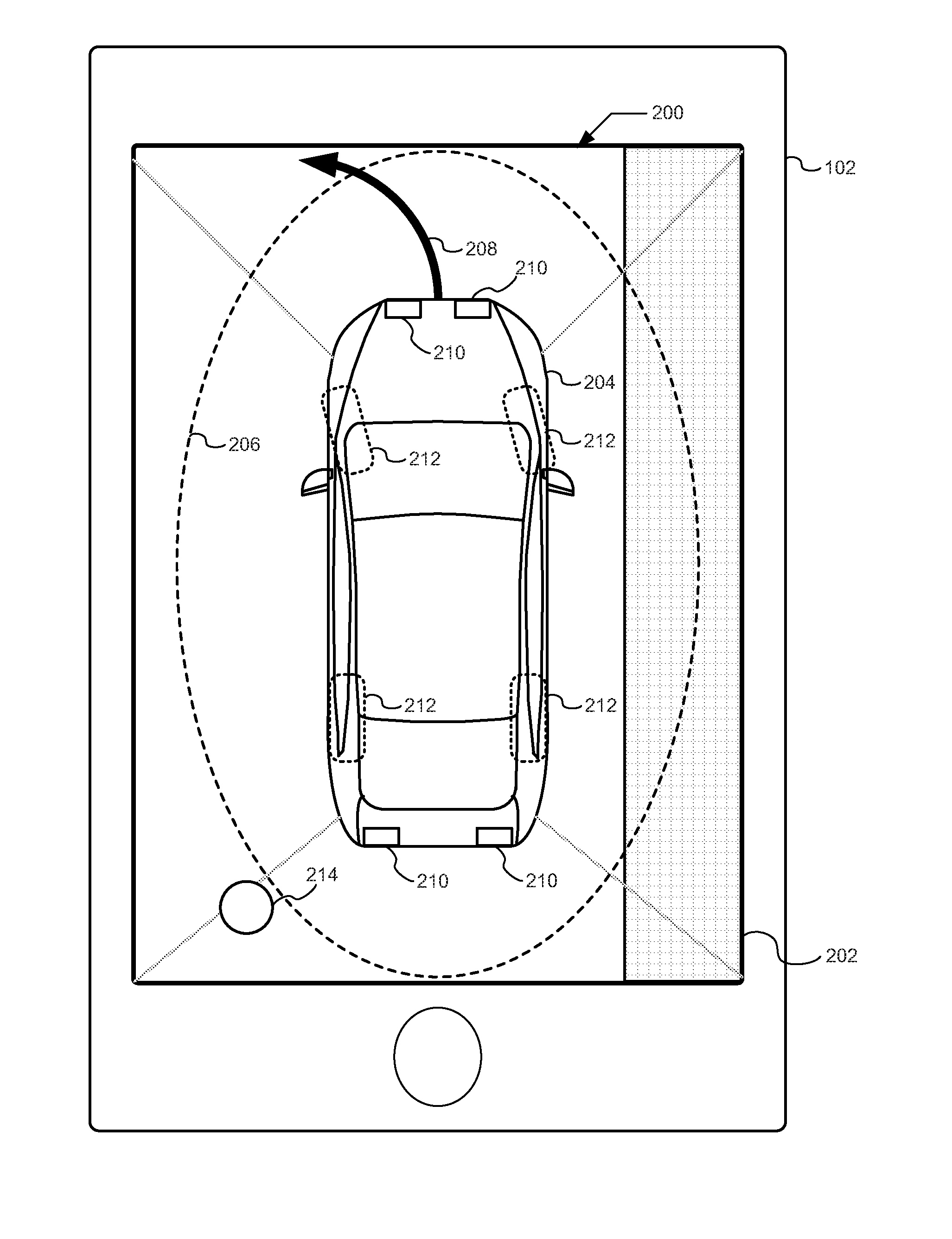
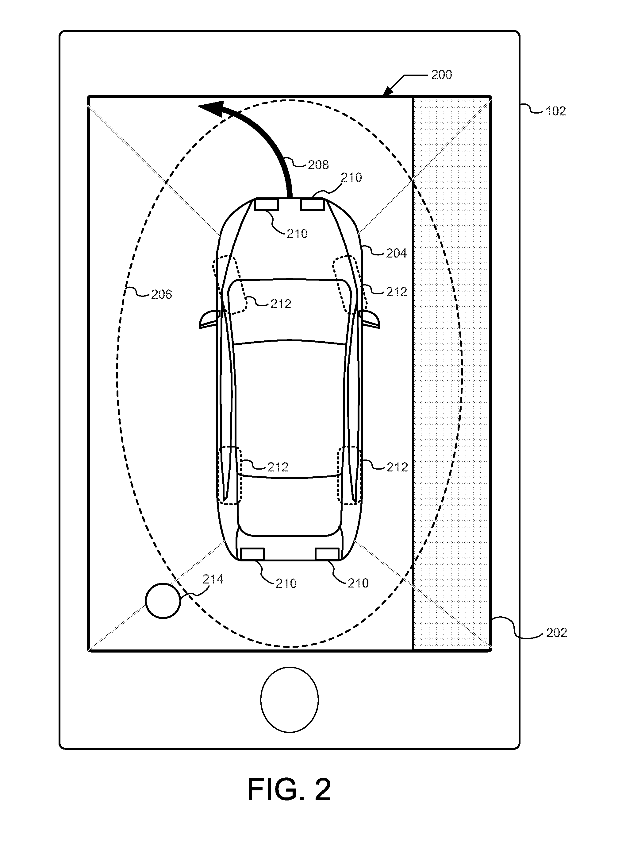
[0028] FIG. 2 illustrates an example interface 200 on the mobile device 102. Based on the localization data provided by the wireless module 106, the interface controller 118 generates the interface 200 and sends the interface 200 to the mobile device 102. The interface controller 118 periodically generates (e.g., every 500 milliseconds, every second, etc.) the interface 200 and sends the updated interface 200 to the mobile device 102. In some examples, the interface controller 118 sends the interface 200 to be displayed on the mobile device 102 when (a) the mobile device 102 is a threshold distance from the vehicle 100 (e.g., halfway between the vehicle 100 and the virtual boundary 116, etc.), (b) the vehicle 100 is autonomously moving below a speed threshold, (c) the continuous input signal is not received from the mobile device 102, (d) when the vehicle 100 detects objects (e.g., via radar, LiDAR, ultra-sonic sensors, etc.) around the vehicle 100 that are within a threshold distance from the vehicle 100, (e) the interface controller 118 determines that the available display region of the mobile device 102 is large enough to accommodate the interface 200, and/or (f) the RePA system in engaged.
[0029] In the illustrated example, the interface 200 includes (a) a 360 degree image 202 generated by the camera module 104 with a representation 204 of the vehicle 100, (b) a representation 206 of the virtual boundary 116, (c) a representation 208 of the planned path that the vehicle will execute to autonomously park, (d) a representation 210 of a state of the lights of the vehicle 100, and (e) a representation 212 of the positions of the wheels of the vehicle 100. Additionally, in some examples, the interface 200 includes a representation 214 of the location of the mobile device 102 and/or a zone of probability (e.g., an area that represents probable locations of the mobile device 102 accounting for localization errors) as determined by the wireless module 106. In some examples, the interface 200 includes indications of the direction of travel of the vehicle 100, the angle of the road, and/or other elements to assist the operator interpret the orientation of the vehicle 100. In some examples, the representation 206 of the virtual boundary 116 is color coded to indicate whether the mobile device 102 (a) is outside the virtual boundary 116 (e.g. color coded red), (b) is inside the virtual boundary 116 but near (e.g., within 0.5 meters, etc.) the edge of the virtual boundary 116 (e.g., color coded yellow), or (c) is inside the virtual boundary 116 (e.g., color coded green). Alternatively or additionally, in some examples, the representation 206 of the virtual boundary 116 may be animated to indicate the relationship of the location of the mobile device 102 to the location of the vehicle 100.
[0030] FIGS. 3A, 3B, and 3C illustrate another interface 300 on the mobile device 192 of FIG. 1. In some examples, the interface controller 118 generates the interface 300, when, for example, the available display region of the mobile device 102 is not large enough to accommodate the interface 200 of FIG. 2. In the illustrated examples, the interface 300 includes (a) an motion track 302, (b) the representation 204 of the vehicle 100, (c) the representation 206 of the virtual boundary 116, (d) the representation 214 of the estimated location of the mobile device 102, and (e) a border indicator 304. The motion track 302 provides an input for the operator to trace with his or her finger via a touch screen of the mobile device 102 to initiate and terminate remote parking of a vehicle 100 and/or provide a continuous input signal. For example, the mobile device 102 sends the continuous input signal to the vehicle 100 as long as the operator is continually tracing a path defined by the motion track 302. In such a manner, the autonomy unit 108 causes the vehicle 100 to move during remote parking only when the user is moving his or her finger (e.g., thumb), conductive stylus, and/or prosthetic digit along the motion track 302. The motion track 302 may be any continuous shape (e.g., non-circular, non-elliptical, wavy, obtuse, etc.) that reflects a natural motion or hand-movement of the user to facilitate the user in easily tracing the motion track 302 that initiates remote parking of the vehicle 100. The border indicator 304 is a region following an edge 306 of the screen of the mobile device 102 that is a number of pixels (e.g., 10 pixels, 20 pixel) wide.
[0031] In the illustrated examples, the motion track 302, the border indicator 304, and/or an interior portion 308 defined by the representation 206 of the virtual boundary 116 are color coded to indicate the relationship of the location of the mobile device 102 to the location of the vehicle 100. The color coding facilitates the operator understanding whether the mobile device 102 is within the virtual boundary 116 with a glance of the screen. Alternatively or additionally, in some examples, the interface controller 118 causes the interface 300 to have other visual indicators, such as blinking or animation, to communicate the status to the RePA system. For example, when the vehicle 100 is in motion, the border indicator 304 may be animated to rotate in a direction indicative of the direction of travel (e.g., forward or reverse) of the vehicle 100. In FIG. 3A, the interface 300 depicts the representation 214 of the mobile device 102 within the representation 206 of the virtual boundary 116. In such an example, the motion track 302, the border indicator 304, and/or the interior portion 308 defined by the representation 206 of the virtual boundary 116 may be color coded green. In FIG. 3B, the interface 300 depicts the representation 214 of the mobile device 102 within the representation 206 of the virtual boundary 116 and near the edge of the virtual boundary 116. In such an example, the motion track 302, the border indicator 304, and/or the interior portion 308 defined by the representation 206 of the virtual boundary 116 may be color coded yellow. In FIG. 3C, the interface 300 depicts the representation 214 of the mobile device 102 outside the representation 206 of the virtual boundary 116. In such an example, the motion track 302, the border indicator 304, and/or the interior portion 308 defined by the representation 206 of the virtual boundary 116 may be color coded red.
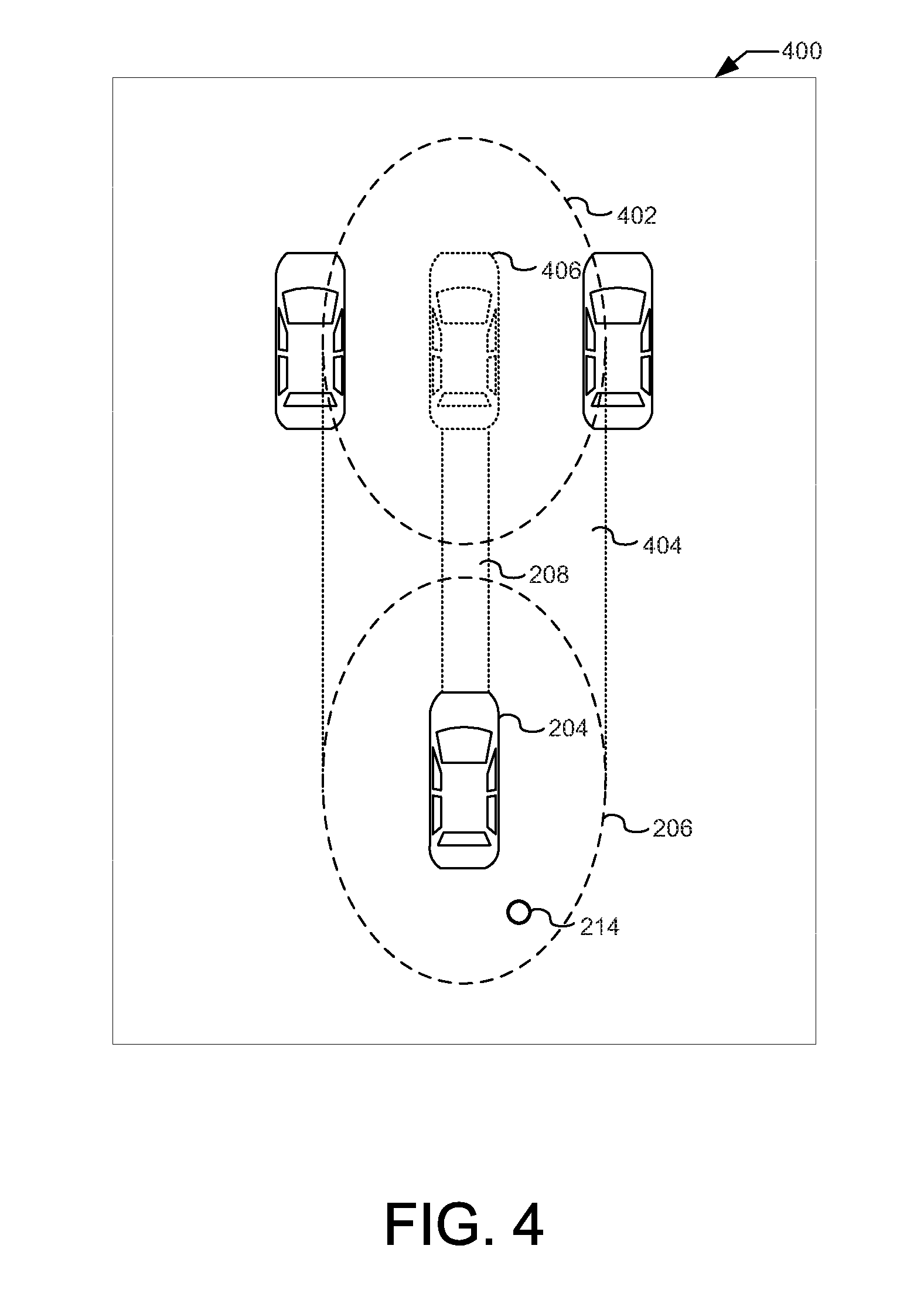
[0032] FIG. 4 illustrates another interface 400 that the interface controller 118 may cause to be displayed on the mobile device 102 of FIG. 1. In the illustrated example, the interface 400 includes (a) the representation 204 of the vehicle 100, (b) the representation 206 of the virtual boundary 116, (c) the representation 214 of the estimated location of the mobile device 102, (d) the representation 208 of the planned path that the vehicle will execute to autonomously park, (e) a representation 402 of an estimated final location of the virtual boundary 116, (f) a representation 404 of an area in which the virtual boundary 116 will exist during the virtual parking maneuver, (g) representation(s) of objects near the path of the vehicle 100, and/or (h) a representation 406 of an estimated final location of the vehicle 100. In some examples, the interface 400 animates the representation 204 of the vehicle 100 to show movement along the path to the final location of the vehicle 100. Additionally, in some examples, the interface 400 includes the video images from the 360 degree camera system to show the area around the vehicle 100. In such examples, as the vehicle 100 moves, the video images from the 360 degree camera system shift on the interface 400 to provide a current view of the area around the vehicle 100 as the vehicle 100 moves.
[0033] FIG. 5 is a block diagram of electronic components 500 of the vehicle 100 of FIG. 1. In the illustrate example, the electronic components 500 include the camera module 104, the wireless module 106, the autonomy unit 108, the cameras 110a-110d, the wireless nodes 114a-114h, and a vehicle data bus 502.
[0034] In the illustrated example, the autonomy unit 108 includes a processor or controller 504 and memory 506. In the illustrated example, the autonomy unit 108 is structured to include interface controller 118. Alternatively, in some examples, the interface controller 118 is incorporated into another electronic control unit (ECU) with its own processor and memory. The processor or controller 504 may be any suitable processing device or set of processing devices such as, but not limited to: a microprocessor, a microcontroller-based platform, a suitable integrated circuit, one or more field programmable gate arrays (FPGAs), and/or one or more application-specific integrated circuits (ASICs). The memory 506 may be volatile memory (e.g., RAM, which can include non-volatile RAM, magnetic RAM, ferroelectric RAM, and any other suitable forms); non-volatile memory (e.g., disk memory, FLASH memory, EPROMs, EEPROMs, non-volatile solid-state memory, etc.), unalterable memory (e.g., EPROMs), read-only memory, and/or high-capacity storage devices (e.g., hard drives, solid state drives, etc). In some examples, the memory 506 includes multiple kinds of memory, particularly volatile memory and non-volatile memory.
[0035] The memory 506 is computer readable media on which one or more sets of instructions, such as the software for operating the methods of the present disclosure can be embedded. The instructions may embody one or more of the methods or logic as described herein. In a particular embodiment, the instructions may reside completely, or at least partially, within any one or more of the memory 506, the computer readable medium, and/or within the processor 504 during execution of the instructions.
[0036] The terms "non-transitory computer-readable medium" and "tangible computer-readable medium" should be understood to include a single medium or multiple media, such as a centralized or distributed database, and/or associated caches and servers that store one or more sets of instructions. The terms "non-transitory computer-readable medium" and "tangible computer-readable medium" also include any tangible medium that is capable of storing, encoding or carrying a set of instructions for execution by a processor or that cause a system to perform any one or more of the methods or operations disclosed herein. As used herein, the term "tangible computer readable medium" is expressly defined to include any type of computer readable storage device and/or storage disk and to exclude propagating signals.
[0037] The vehicle data bus 502 communicatively couples the camera module 104, the wireless module 106, and the autonomy unit 108. In some examples, the vehicle data bus 502 includes one or more data buses. The vehicle data bus 502 may be implemented in accordance with a controller area network (CAN) bus protocol as defined by International Standards Organization (ISO) 11898-1, a Media Oriented Systems Transport (MOST) bus protocol, a CAN flexible data (CAN-FD) bus protocol (ISO 11898-7) and/a K-line bus protocol (ISO 9141 and ISO 14230-1), and/or an Ethernet.TM. bus protocol IEEE 802.3 (2002 onwards), etc.
[0038] FIG. 6 is a flowchart of a method to assist an operator operating the remote park assist system of the vehicle 100 of FIG. 1, which may be implemented by the electronic components 500 of FIG. 5. Initially, at block 602, the interface controller 118 waits until the remote parking system is enabled. In some examples, the operator enables the remote parking system through an infotainment system (e.g., Sync.RTM. by Ford, etc.) on a center console display. For example, after stopping the vehicle 100 and before exiting the cabin of the vehicle 100, the operator may enable the remote parking assist system. Enabling the remote parking system causes the autonomy unit 108 to, for example, identify a potential parking spot and plan a path into the parking spot. At block 604, after the remote parking assist system has been enabled, the interface controller 118 tracks the location of the mobile device 102 using the localization data from the wireless module 106. At block 606, the camera module 104 generates the 360 degree composite image from the images received from the cameras 110a-110d. At block 608, the interface controller 118 generates an interface (e.g., the interface 200, 300, 400 of FIGS. 2, 3A, 3B, 3C, and 4 above, etc.) based on the location of mobile device 102 relative to the location of the vehicle 100. At block 610, the interface controller 118 sends instructions to the mobile device 102 that cause the mobile device 102 to display the interface generated at block 606.
[0039] At block 612, the interface controller 118 determines whether the mobile device 102 is within the virtual boundary 116 based on the localization data received at block 604. When the mobile device 102 is not within the virtual boundary 116, the method continues at block 614. Otherwise, when the mobile device 102 is with the virtual boundary 116, the method continues at block 618. At block 614, the interface controller 118 adjusts the interface for the mobile device 102 to indicate the state of the remote parking system. For example, the interface controller 118 may cause the border indicator 304 on the interface 300 to flash red. At block 616, the autonomy unit 108 prevents autonomous movement of the vehicle 100.
[0040] At block 618, the interface controller 118 determines whether the mobile device 102 is near (e.g., within 0.5 meters) the virtual boundary 116. When the mobile device 102 is near the virtual boundary 116, the method continues to block 620. Otherwise, when the mobile device 102 is not near the virtual boundary 116, the method continues to block 624. At block 620, the interface controller 118 adjusts the interface for the mobile device 102 to indicate the state of the remote parking system. For example, the interface controller 118 may cause the border indicator 304 on the interface 300 to turn yellow and generate a text-based warning. At block 622, the autonomy unit 108 allows autonomous movement of the vehicle 100.
[0041] At block 624, the interface controller 118 adjusts the interface for the mobile device 102 to indicate the state of the remote parking system. For example, the interface controller 118 may cause the border indicator 304 on the interface 300 to turn green. At block 626, the autonomy unit 108 allows autonomous movement of the vehicle 100.
[0042] The flowchart of FIG. 6 is representative of machine readable instructions stored in memory (such as the memory 506 of FIG. 5) that comprise one or more programs that, when executed by a processor (such as the processor 504 of FIG. 5), cause the vehicle 100 to implement the example interface controller 118 and/or, more generally, the example autonomy unit 108 of FIGS. 1 and 5. Further, although the example program(s) is/are described with reference to the flowchart illustrated in FIG. 6, many other methods of implementing the example interface controller 118 and/or, more generally, the example autonomy unit 108 may alternatively be used. For example, the order of execution of the blocks may be changed, and/or some of the blocks described may be changed, eliminated, or combined.
[0043] In this application, the use of the disjunctive is intended to include the conjunctive. The use of definite or indefinite articles is not intended to indicate cardinality. In particular, a reference to "the" object or "a" and "an" object is intended to denote also one of a possible plurality of such objects. Further, the conjunction "or" may be used to convey features that are simultaneously present instead of mutually exclusive alternatives. In other words, the conjunction "or" should be understood to include "and/or". As used here, the terms "module" and "unit" refer to hardware with circuitry to provide communication, control and/or monitoring capabilities, often in conjunction with sensors. "Modules" and "units" may also include firmware that executes on the circuitry. The terms "includes," "including," and "include" are inclusive and have the same scope as "comprises," "comprising," and "comprise" respectively.
[0044] The above-described embodiments, and particularly any "preferred" embodiments, are possible examples of implementations and merely set forth for a clear understanding of the principles of the invention. Many variations and modifications may be made to the above-described embodiment(s) without substantially departing from the spirit and principles of the techniques described herein. All modifications are intended to be included herein within the scope of this disclosure and protected by the following claims.
* * * * *
D00000
D00001
D00002
D00003
D00004
D00005
D00006
XML
uspto.report is an independent third-party trademark research tool that is not affiliated, endorsed, or sponsored by the United States Patent and Trademark Office (USPTO) or any other governmental organization. The information provided by uspto.report is based on publicly available data at the time of writing and is intended for informational purposes only.
While we strive to provide accurate and up-to-date information, we do not guarantee the accuracy, completeness, reliability, or suitability of the information displayed on this site. The use of this site is at your own risk. Any reliance you place on such information is therefore strictly at your own risk.
All official trademark data, including owner information, should be verified by visiting the official USPTO website at www.uspto.gov. This site is not intended to replace professional legal advice and should not be used as a substitute for consulting with a legal professional who is knowledgeable about trademark law.