Monitoring Sensor For Metered Amounts Of Powder
Mueller; Daniel ; et al.
U.S. patent application number 16/248380 was filed with the patent office on 2019-07-18 for monitoring sensor for metered amounts of powder. The applicant listed for this patent is Harro Hoefliger Verpackungsmaschinen GmbH. Invention is credited to Daniel Mueller, Thomas Puppich.
| Application Number | 20190219533 16/248380 |
| Document ID | / |
| Family ID | 61017798 |
| Filed Date | 2019-07-18 |

| United States Patent Application | 20190219533 |
| Kind Code | A1 |
| Mueller; Daniel ; et al. | July 18, 2019 |
MONITORING SENSOR FOR METERED AMOUNTS OF POWDER
Abstract
A monitoring sensor for metered amounts of powder includes a sensor socket to channel the metered amount of powder through it and a sensor base body, in which the sensor socket is held interchangeably. A holding plate is attached to the interchangeable sensor socket. The sensor base body has a contact surface for the holding plate. The monitoring sensor includes a holding magnet for pressing the holding plate against the contact surface.
| Inventors: | Mueller; Daniel; (Allmersbach im Tal, DE) ; Puppich; Thomas; (Allmersbach im Tal, DE) | ||||||||||
| Applicant: |
|
||||||||||
|---|---|---|---|---|---|---|---|---|---|---|---|
| Family ID: | 61017798 | ||||||||||
| Appl. No.: | 16/248380 | ||||||||||
| Filed: | January 15, 2019 |
| Current U.S. Class: | 1/1 |
| Current CPC Class: | F16B 2001/0035 20130101; G01F 25/0092 20130101; G01N 27/226 20130101; G01F 25/0084 20130101 |
| International Class: | G01N 27/22 20060101 G01N027/22 |
Foreign Application Data
| Date | Code | Application Number |
|---|---|---|
| Jan 18, 2018 | EP | 18152376.2 |
Claims
1. A monitoring sensor for metered amounts of powder, the monitoring sensor comprising: a sensor socket configured to channel the metered amount of powder therethrough; a sensor base body; said sensor socket being held interchangeably in said sensor base body; a holding plate attached to said sensor socket; said sensor base body having a contact surface for said holding plate; and, said monitoring sensor including a holding magnet configured to press said holding plate against said contact surface.
2. The monitoring sensor of claim 1, wherein: said holding plate is made of a magnetically attractable material; and, said holding magnet is positioned in said sensor base body.
3. The monitoring sensor of claim 1, wherein: said sensor base body has a through opening formed therein; and, said sensor socket, in a mounted state, is held free of play in said through opening.
4. The monitoring sensor of claim 1, wherein, in a mounted state, an electrically conducting connection exists between said holding plate and said sensor base body.
5. The monitoring sensor of claim 1 further comprising a blast nozzle for said sensor socket.
6. The monitoring sensor of claim 5, wherein: said sensor socket defines a longitudinal axis; and, said blast nozzle, when viewed in a cross section of said sensor socket, is oriented tangentially to said longitudinal axis of said sensor socket.
Description
CROSS REFERENCE TO RELATED APPLICATION
[0001] This application claims priority of European patent application no. 18152376.2, filed Jan. 18, 2018, the entire content of which is incorporated herein by reference.
BACKGROUND OF THE INVENTION
[0002] Especially in the pharmaceutical industry, powder-like formulations are employed, wherein suitable partial amounts from a powder stockpile need to be precisely measured or metered for the respective application. This occurs, for example, by means of roller or disk dispensers, which have metering bores with a calibrated volume. These metering bores are filled with the powder, so that partial amounts are produced with the volume of the respective metering bore. Such partial amounts can then be blown out and sent on to further processing, especially for filling in a target container.
[0003] With increasing demands on process safety, especially as regards the target amounts obtained, there is a need to check the measured amounts of powder for compliance with certain amount tolerances. For this, monitoring sensors are used, including in one known configuration a sensor base body and a sensor socket for channeling the metered amount of powder through it. The metered amount of powder is channeled through the sensor socket and herein subjected to a capacitive mass determination. For a precise and reproducible measurement result, a geometrical adaptation of the sensor socket to the format of the amount of powder to be tested is required. But since powders in different batches with different formats are processed on the same dosing device, the need for the geometrical adaptation also leads to different sensor sockets having to be used.
[0004] So as not to need to keep on hand many different monitoring sensors, configurations are used in which the sensor sockets are held interchangeably in the sensor base body. The user need herein only keep on hand a selection of format-dependent adapted sensor sockets, while the sensor base body including its measuring and control electronics can be kept the same. During every format change, the adapting work on the monitoring sensor is limited to removing the existing sensor socket and replacing it with a sensor socket adapted to the format which is going to be processed.
[0005] Herein various difficulties occur in practice. Thus far, the sensor sockets have been inserted into the sensor base body without locking. Due to vibrations or other actions of force, however, an axial shifting of the sensor sockets cannot be ruled out. Furthermore, a rotational movement of the sensor sockets was also possible. The mentioned unwanted relative movements may have a negative impact on the quality of the measurement signal and in the extreme case may even result in damage to the sensor. Attempts to attach them with O-rings have resulted in a tendency to damage when the sockets are changed. On the whole, the pulling out and the installing of the sensor sockets requires effort, which makes it difficult to retrofit the monitoring sensors installed in the machine, given the correspondingly cramped space conditions.
SUMMARY OF THE INVENTION
[0006] It is an object of the invention to further develop a monitoring sensor such that the interchangeability of the sensor socket is improved.
[0007] This object can, for example, be achieved via a monitoring sensor for metered amounts of powder. The monitoring sensor includes: a sensor socket configured to channel the metered amount of powder therethrough; a sensor base body; the sensor socket being held interchangeably in the sensor base body; a holding plate attached to the sensor socket; the sensor base body having a contact surface for the holding plate; and, the monitoring sensor including a holding magnet configured to press the holding plate against the contact surface.
[0008] According to an aspect of the invention, it is provided that on the interchangeable sensor socket there is attached a holding plate, by which the sensor socket and the holding plate form a jointly interchangeable unit. Furthermore, the sensor base body has a bearing face or contact surface for the holding plate, while the monitoring sensor includes a holding magnet for pressing the holding plate against the contact surface. It may be herein expedient that the holding magnet is attached to the holding plate, while the sensor base body has appropriately magnetically attractable properties. Preferably, however, the holding plate is made of a magnetically attractable material, while the holding magnet is positioned in the sensor base body. In any case, the invention accomplishes the fact that the sensor socket is positionally exactly fixed in the sensor base body. The magnetic pressing force reliably prevents shifting and rotational movements of the sensor socket relative to the sensor base body. Even so, when pulling out the socket the magnetic force can be manually overcome without major effort. The respective sensor socket can be easily removed or inserted without the presence of clamps or the like. The magnetic force which acts only in the immediate vicinity of the installation position does not interfere with this, yet at the same time it ensures a precise positioning in the operating position. A format change can be carried out without any problems, due to the significantly easier changeover of the sensor sockets. The danger of damaging the sensor during the format change is significantly reduced. Thanks to the precise positional fixing, the reliability of the measurement is increased, while at the same time further costs due to the errors and problems known in the prior art are decreased.
[0009] In a further embodiment, a through opening is formed in the sensor base body, wherein the sensor socket in the mounted condition is held free of play in the through opening. In this way, it is achieved that the sensor socket is positioned and centered exactly in the plane of the contact surface and furthermore cannot perform any tilting movements, either. The holding plate pressed against the contact surface ensures a fixation in the axial direction, while the holding magnet positioned eccentrically to the longitudinal axis prevents a rotational movement of the structural unit from the sensor socket and the holding plate about the longitudinal axis. All of this results in a positioning and fixation in all lateral and rotational degrees of freedom, wherein this positioning adopted once is reliably maintained during the operation. This contributes to the consistency and precision of the measurement results.
[0010] Advantageously, in the mounted condition an electrically conducting connection exists between the holding plate and the sensor base body, accordingly an electrical grounding of the holding plate with respect to the sensor base body is produced. In this way, on the one hand, the measurement field inside the sensor socket is electrically shielded against external interfering influences, while on the other hand a scattering of the field lines of the measurement field to the outside from the measurement section is reduced. Thanks to the effective separation achieved between the measuring section and the surroundings, the reproducibility of the measurement result is further improved.
[0011] The monitoring sensor can have a blast nozzle for the sensor socket. The blast nozzle when viewed in the cross section of the sensor socket is advisedly oriented tangentially to a longitudinal axis of the sensor socket. It has to be indeed observed that powder residues can become deposited in the sensor socket, wherein the measurement value of the sensor changes on account of a change in the dielectric caused by the powder deposit. The blast nozzle now allows a blowing out and thus a cleaning of the interior of the sensor socket when needed or in fixedly predetermined cycles. The removal of possibly clinging powder residues that is accomplished in this way ensures constancy of the dielectric parameters, so that corresponding measurement errors are avoided. The eccentric, tangential orientation of the blast nozzle results in a helical swirling inside the sensor socket, which improves the cleaning action.
BRIEF DESCRIPTION OF THE DRAWINGS
[0012] The invention will now be described with reference to the drawings wherein:
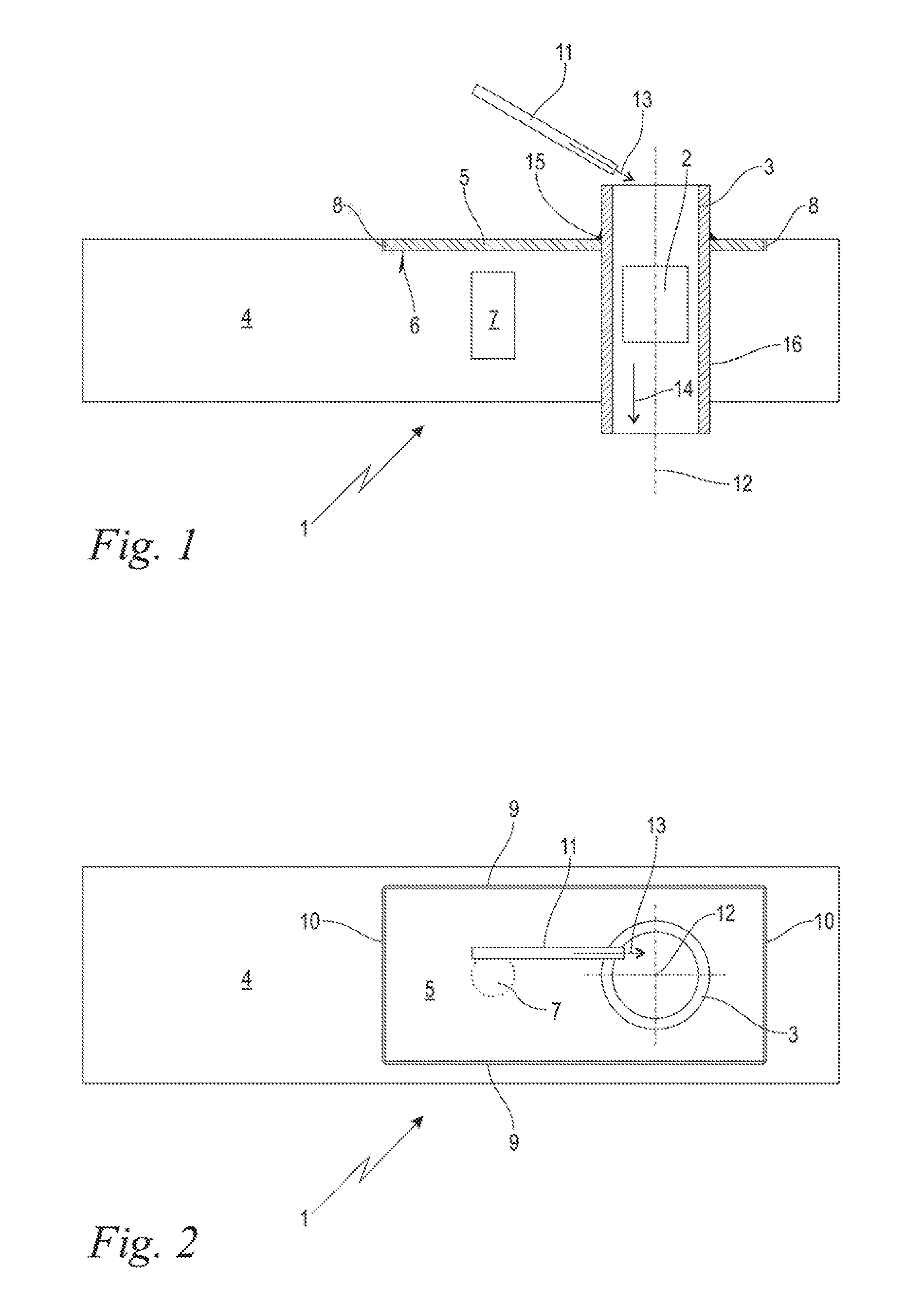
[0013] FIG. 1 shows in a schematic longitudinal section representation a monitoring sensor with sensor socket, holding plate, holding magnet and blast nozzle; and,
[0014] FIG. 2 shows in a schematic top view the monitoring sensor of FIG. 1 with details on the positioning of the holding plate and on the tangential orientation of the blast nozzle.
DESCRIPTION OF THE PREFERRED EMBODIMENTS OF THE INVENTION
[0015] FIG. 1 shows in a schematic longitudinal section representation a monitoring sensor 1 configured according to an embodiment of the invention for the mass determination of metered amounts of powder 2 only indicated schematically here. The metered amounts of powder 2 shown here are pharmaceutical powder plugs compacted into so-called pellets, which plugs have been previously metered and measured in a sliding dispenser in a previously known manner, and therefore not described here. The term amounts of powder 2 chosen here, however, includes in the scope of the disclosure loose, amorphous amounts of powder and also amounts of powder compressed into quasi-solids, such as pellets, tablets, or the like, especially from the pharmaceutical industry, but also from other industries such as for example from the food supplement industry. The metering may also occur in a roller dispenser, in a disk dispenser, via a pipette or the like, in a previously known manner. The monitoring sensor 1 is a sensor for capacitive mass determination of the amount of powder 2 and includes for this purpose a sensor socket 3 as well as a sensor base body 4. The sensor socket 3 extends along a longitudinal axis 12, running vertically here as an example, and serves to channel the metered amount of powder 2 through it from top to bottom corresponding to an arrow 14. The sensor base body 4 contains a capacitive measurement electronics, not shown. An electrical capacitance is formed, whose electric field reaches through the interior of the sensor socket 3. The amount of powder 2 passing through results in a dielectric change in the capacitance, which can be detected by the monitoring sensor 1 and converted into a measurement signal for the mass determination of the amount of powder 2.
[0016] For an exact and reproducible measurement, the internal cross section of the sensor socket 3 should be adapted to the format of the amount of powder 2 to be measured. The sensor socket 3 is therefore held interchangeably on the sensor base body 4. For measurements of amounts of powder 2 with differing format, differing sensor sockets 3 adapted to the format are inserted into the sensor base body 4 shown here, after the sensor socket 3 shown here has been removed.
[0017] In order to achieve the mentioned interchangeability, a holding plate 5 is attached to the sensor socket 3 and forms an interchangeable unit together with the sensor socket 3. The mechanical connection between the holding plate 5 and the sensor socket 3 is formed here by an encircling adhesive joint is, indicated schematically. But a screwed or clamped connection of the like may also be expedient. Corresponding to the structural unit from sensor socket 3 and holding plate 5, the sensor base body 4 has a through opening 16 for the sensor socket 3 and also a bearing face or contact surface 6 for the holding plate 5. In the embodiment shown, the contact surface 6 is formed by a bottom of a receiving pocket 8, in which the holding plate 5 comes to rest.
[0018] In the sensor base body 4 there is arranged a holding magnet 7 and is positioned close to the contact surface 6 such that, in the operating position shown, the holding plate 5 including a magnetically attractable material is pressed against the contact surface 6. It may be herein expedient that the corresponding end face of the holding magnet 7 forms a portion of the contact surface 6 and consequently comes directly into contact with the holding plate 5. In the embodiment shown, however, the holding magnet 7 is positioned at a certain spacing from the contact surface 6, wherein the contact surface 6 covers the holding magnet 7 free of interruptions. By suitable dimensioning of the mentioned spacing, an adaptation of the active holding force can be produced, while the closed surface of the contact surface 6 contributes to the mechanical robustness and to easy cleanability. Alternatively to the arrangement shown, it may also be expedient to attach the holding magnet 7 on the holding plate 5, while the sensor base body 4 is formed at least in sections by a magnetically attractable material in the region of the contact surface 6. In any case, an axial pressing force is created, which ensures a permanent fixation of the sensor socket 3 relative to the sensor base body 4 during the operation, while at the same time an easy interchangeability is produced.
[0019] The sensor socket 3 includes an electromagnetically permeable, nonconductive material, namely, from a nonconductive plastic, for which in an embodiment PEEK (polyether ether ketone) is chosen. In this way, an electromagnetic, here capacitive, measurement field can be established in the interior of the sensor socket. The holding plate 5, on the other hand, is of an electrically conductive material, and the contact between the holding plate 5 and the contact surface 6 is also electrically conductive. The result therefrom is an electrical grounding of the holding plate 5 with respect to the sensor base body 4, as a consequence of which the measurement section situated in the interior of the sensor socket 3 for the mass determination of the amount of powder 2 is electrically shielded against external interfering influences.
[0020] It may further be seen in FIG. 1 that the monitoring sensor 1 has a schematically indicated blast nozzle 11 for the sensor socket 3. When needed, or at regular intervals, pressurized air or another suitable gas can be blown into the interior of the sensor socket 3 according to an arrow 13, in order to blow out powder residues possibly clinging there. For this, the blast nozzle 11 is inclined at an acute angle to the longitudinal axis 12 in the longitudinal section of the sensor socket 3, so that the blowing direction according to the arrow 13 lies neither parallel nor perpendicular to the longitudinal axis 12.
[0021] FIG. 2 shows in a schematic top view the monitoring sensor 1 of FIG. 1. It can be noticed here, first of all, that the blast nozzle 11 when viewed in the cross section of the sensor socket 3 is oriented excentrically, that is, tangentially to the longitudinal axis 12 of the sensor socket. It is seen from this, and considered together with FIG. 1, that a helical flow path is adjusted during the blowing out in the interior of the sensor socket 3, which is circular in the cross section.
[0022] Furthermore, it emerges from the consideration with FIGS. 1 and 2 that the receiving pocket 8 (FIG. 1) in the top view of FIG. 2 is bounded by two parallel opposite peripheral walls 9 as well as by two however likewise parallel opposite peripheral walls 10 running at right angles to the former walls. The holding plate 5, when viewed in the plane of the contact surface 6, is somewhat smaller in dimension than the receiving pocket 8, therefore, that is, a gap remains each time between the edges of the holding plate 5 and the peripheral walls 9, 10 of the receiving pocket 8. The mounted sensor socket 3, on the other hand, sits free of play in the through opening 16 of the sensor base body 4. This seating free of play holds and centers the structural unit from sensor socket 3 and holding plate 5 in spatial directions perpendicular to the longitudinal axis 12, that is, in the plane of the contact surface 6, and furthermore prevents tilting movements about axes situated in the plane of the contact surface 6. Perpendicular to this, that is, in the direction of the longitudinal axis 12, the relative positioning is produced by supporting the holding plate 5 on the contact surface 6. The magnetic pressing force of the holding plate 5, extending perpendicular to the longitudinal axis 12, against the contact surface 6 furthermore brings about a positioning and securing of the structural unit from sensor socket 3 and holding plate 5 with regard to rotational movements about the longitudinal axis 12. Starting from this defined operating position, which is thus dictated and adopted, lateral shifting movements in all three spatial directions and also rotational and tilting movements about all three spatial axes are reliably prevented.
[0023] Upon a format change in the amounts of powder 2 to be measured, the structural unit from sensor socket 3 and holding plate 5 may now be pulled out from the sensor base body 4 coaxially to the longitudinal axis 12, overcoming the magnetic holding force. Conversely, a different structural unit of this kind with cross section of the sensor socket 3 adapted to the new format of the amount of powder 2, yet with the same geometrical configuration of the holding plate 5, may now be used. The acting magnetic force results in a fixation and quasi-locking of the used sensor socket 3 in a relative position to the sensor base body 4 which is exactly oriented and also no longer changeable during the operation.
[0024] It is understood that the foregoing description is that of the preferred embodiments of the invention and that various changes and modifications may be made thereto without departing from the spirit and scope of the invention as defined in the appended claims.
* * * * *
D00000
D00001
XML
uspto.report is an independent third-party trademark research tool that is not affiliated, endorsed, or sponsored by the United States Patent and Trademark Office (USPTO) or any other governmental organization. The information provided by uspto.report is based on publicly available data at the time of writing and is intended for informational purposes only.
While we strive to provide accurate and up-to-date information, we do not guarantee the accuracy, completeness, reliability, or suitability of the information displayed on this site. The use of this site is at your own risk. Any reliance you place on such information is therefore strictly at your own risk.
All official trademark data, including owner information, should be verified by visiting the official USPTO website at www.uspto.gov. This site is not intended to replace professional legal advice and should not be used as a substitute for consulting with a legal professional who is knowledgeable about trademark law.