Tank For Heat Exchanger And Method For Manufacturing The Tank
WILSON; Nicholas ; et al.
U.S. patent application number 15/874047 was filed with the patent office on 2019-07-18 for tank for heat exchanger and method for manufacturing the tank. The applicant listed for this patent is DENSO International America, Inc.. Invention is credited to Justin HARRIS, Nicholas WILSON.
| Application Number | 20190219345 15/874047 |
| Document ID | / |
| Family ID | 67213717 |
| Filed Date | 2019-07-18 |


View All Diagrams
| United States Patent Application | 20190219345 |
| Kind Code | A1 |
| WILSON; Nicholas ; et al. | July 18, 2019 |
TANK FOR HEAT EXCHANGER AND METHOD FOR MANUFACTURING THE TANK
Abstract
A tank portion defines a space therein and has an opening on one side. A foot portion is in a plate shape extending radially outward from a bottom end of the tank portion on the one side. A core plate covers the opening and has a base portion and a holder portion. The base portion is in an elongated rectangular plate shape having first and second long lateral sides and a short lateral side. The holder portion includes a first holder at the first long lateral side, a second holder at the second long lateral side, and a third holder at the short lateral side, each gripping the foot portion. All the first holder, the third holder, and the second holder are one piece continuously extending along the first long lateral side, the short lateral side, and the second long lateral side.
| Inventors: | WILSON; Nicholas; (Grosse Pointe Park, MI) ; HARRIS; Justin; (Southfield, MI) | ||||||||||
| Applicant: |
|
||||||||||
|---|---|---|---|---|---|---|---|---|---|---|---|
| Family ID: | 67213717 | ||||||||||
| Appl. No.: | 15/874047 | ||||||||||
| Filed: | January 18, 2018 |
| Current U.S. Class: | 1/1 |
| Current CPC Class: | F28F 2255/143 20130101; B21D 22/21 20130101; F28F 2230/00 20130101; F28F 9/001 20130101; F28F 2275/122 20130101; F28F 9/0226 20130101; F28F 1/126 20130101; B21D 53/02 20130101; F28F 9/0221 20130101; F28F 21/084 20130101; F28D 1/05366 20130101; F28F 2255/00 20130101 |
| International Class: | F28F 9/02 20060101 F28F009/02; F28F 9/00 20060101 F28F009/00; F28F 21/08 20060101 F28F021/08; F28D 1/053 20060101 F28D001/053 |
Claims
1. A tank for a heat exchanger, the tank comprising: a tank part including a tank portion and a foot portion, the tank portion defining a space therein and having an opening on one side, the foot portion being in a plate shape extending radially outward from a bottom end of the tank portion on the one side; and a core plate covering the opening, the core plate including a base portion and a holder portion, wherein the base portion is in an elongated rectangular plate shape having a first long lateral side, a second long lateral side, and a short lateral side, the holder portion includes a first holder at the first long lateral side, a second holder at the second long lateral side, and a third holder at the short lateral side, each gripping the foot portion, and all the first holder, the third holder, and the second holder are one piece continuously extending along the first long lateral side, the short lateral side, and the second long lateral side.
2. The tank according to claim 1, wherein the third holder is seamless with the first holder and the second holder at two corners of the holder portion.
3. The tank according to claim 2, wherein the first holder, the third holder, and the second holder have a U-shaped cross section forming a first linear channel, a third linear channel, and a second linear channel, respectively, and the foot portion is partially accommodated in the first linear channel, the third linear channel, and the second linear channel.
4. The tank according to claim 3, wherein the foot portion is partially covered with the third holder at one end, and the foot portion is exposed at an other end.
5. The tank according to claim 4, wherein the foot portion is covered with the first holder, the third holder, and the second holder at the two corners of the holder portion, and the foot portion is exposed at remaining two corners of the holder portion.
6. The tank according to claim 3, wherein the foot portion is partially covered with the third holder at one end, the tank further comprising: a cap to cover an other end of the foot portion.
7. The tank according to claim 5, wherein the core plate further has a tab integrally formed with the base portion and extending radially outward from an other short lateral side of the base portion, and the tab is crimped on the foot portion at the other end.
8. The tank according to claim 1, further comprising: a seal member interposed between the foot portion and the base portion.
9. The tank according to claim 8, wherein the seal member is insert-molded with the foot portion.
10. The tank according to claim 1, wherein the first long lateral side has only the first holder as a component for gripping the foot portion, and the second long lateral side has only the second holder as a component for gripping the foot portion.
11. The tank according to claim 1, wherein the first holder extends continuously throughout the first long lateral side, the second holder extends continuously throughout the second long lateral side, and the third holder extends continuously throughout the short lateral side.
12. A method for manufacturing a tank for a heat exchanger, the method comprising: forming a core plate, the forming includes: setting a blank between a die and a punch and positioning a base portion, which is located at a center of the blank, relative to the punch; moving the punch into a die cavity of the die to deep draw the blank and to partially draw margins, which are located around a periphery of the base portion, while tilting the margins along a die surface defining the die cavity; and bending the margins, as tilted, toward the punch to form a first holder, a second holder, and a third holder to be one piece continuously extending along the periphery of the base portion and to have a U-shaped cross section, such that the first holder, the second holder, the third holder, and the base portion define a slot, which is in a planar shape, thereamong; and mounting a tank part, which includes a foot portion in a plate shape, to the core plate by inserting the foot portion through the slot linearly along the first holder and the second holder.
13. The method according to claim 12, further comprising: abutting, subsequent to the mounting, the foot portion to the third holder to position the foot portion relative to the core plate in a longitudinal direction.
14. The method according to claim 13, further comprising: pressing, subsequent to the abutting, the first holder, the second holder, and the third holder onto the foot portion.
15. The method according to claim 14, further comprising: forming a tab on one lateral side of the base portion to extend radially outward from the one lateral side; and crimping, subsequent to the abutting, the tab onto the foot portion.
16. The method according to claim 12, the bending further includes: fusing the first holder with the third holder at a corner therebetween; and fusing the second holder with the third holder at a corner therebetween.
Description
TECHNICAL FIELD
[0001] The present disclosure relates to a tank for a heat exchanger. The present disclosure further relates a method for manufacturing the tank.
BACKGROUND
[0002] A vehicle is generally equipped with a heat exchanger for a thermal system. A heat exchanger generally includes a tank for receiving thermal medium.
SUMMARY
[0003] According to an aspect of the disclosure, a tank for a heat exchanger includes a tank part and a core plate. The tank part is affixed to the core plate.
BRIEF DESCRIPTION OF THE DRAWINGS
[0004] The above and other objects, features and advantages of the present invention will become more apparent from the following detailed description made with reference to the accompanying drawings. In the drawings:
[0005] FIG. 1 is a perspective view showing a thermal system including a heat exchanger;
[0006] FIG. 2 is a perspective view showing a tank for the heat exchanger;
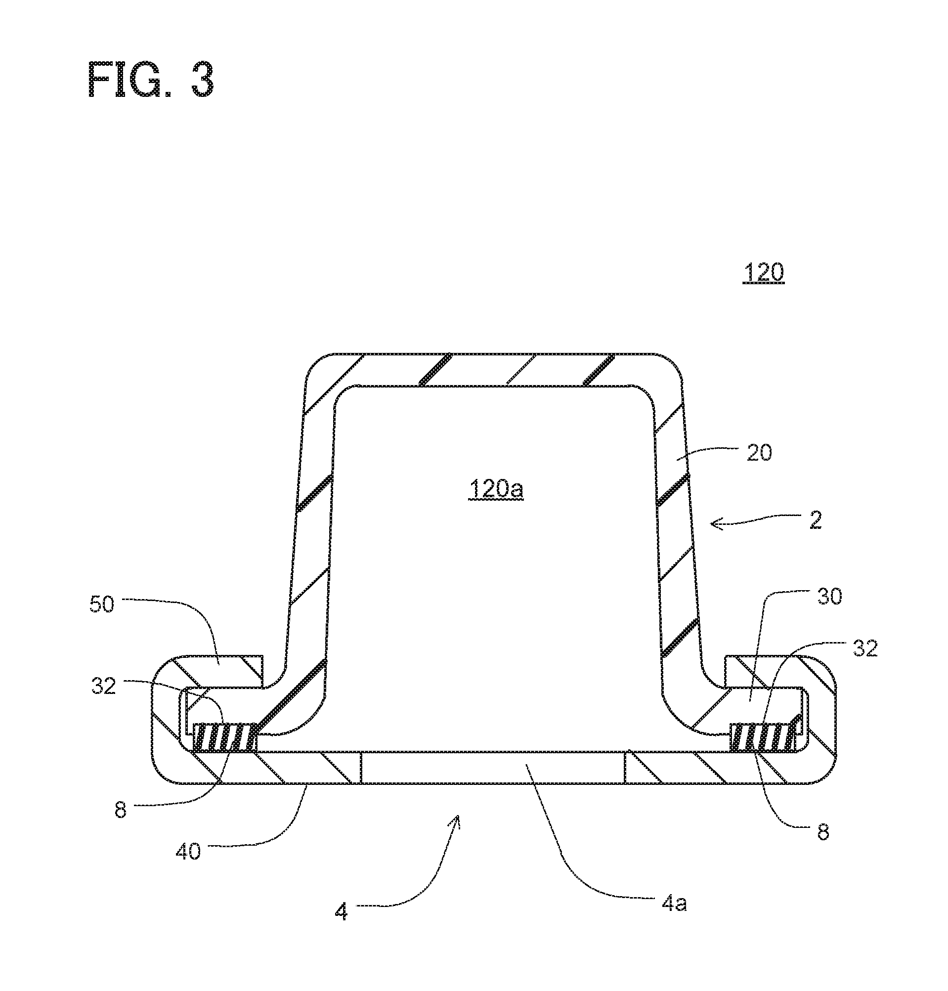
[0007] FIG. 3 is a cross sectional view taken along a line III-III in FIG. 2;
[0008] FIG. 4A is a perspective view showing a tank part, FIG. 4B is a perspective view showing a sealing member, and FIG. 4C is a perspective view showing a core plate,
[0009] FIGS. 5 to 8 are perspective views showing a manufacturing process for the tank;
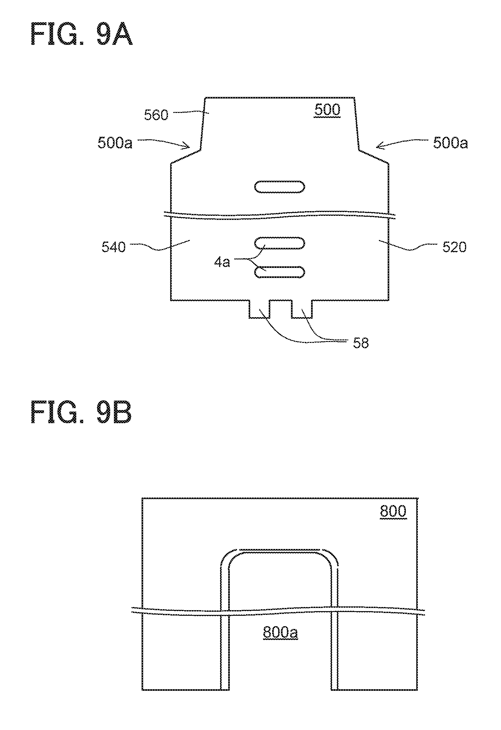
[0010] FIG. 9A is a plan view showing a blank, and FIG. 9B is a plan view showing a die;
[0011] FIGS. 10 to 14 are perspective views showing a manufacturing process for the core plate;
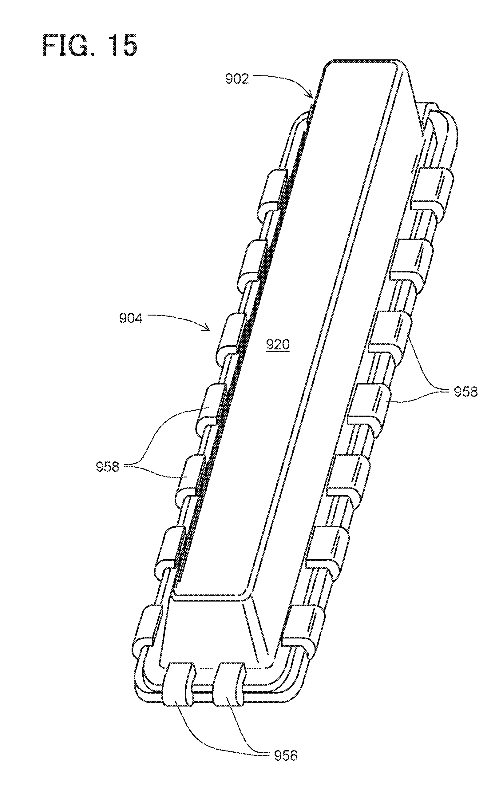
[0012] FIG. 15 is a perspective view showing an example of a tank;
[0013] FIG. 16 is a perspective view showing a cap according to a second embodiment; and
[0014] FIG. 17 is a cross sectional view showing a tank according to a third embodiment.
DETAILED DESCRIPTION
Example
[0015] FIG. 15 shows an example of a tank 920 for a heat exchanger. The tank 920 includes a tank part 902 and a core plate 904. The core plate 904 has multiple tabs 958 arranged along its periphery. The tabs 958 are crimped onto the tank part 902 thereby to affix the tank part 902 to the core plate 904. The tank part 902 and the core plate 904 interpose a seal member (not shown) therebetween. In this example, the tabs 958 are segmented into a large number of pieces. This example therefore may result in inconsistent seal between the tank part 902 and the core plate 904. In addition, the segmented tabs 958 may need enhanced rigidity to securely grip the tank part 902 and the seal member to prevent leakage of internal liquid. The segmented tabs 958 may require a large number of manufacturing processes to crimp the tabs 958.
[0016] According to one aspect of the disclosure, a tank has a slide-in configuration where a tank part is inserted along holders of a core plate. The holders are continuous along long lateral sides of the core plate, respectively. This configuration may enable consistent sealing and may require less manufacturing process.
First Embodiment
[0017] As follows, a first embodiment of the present disclosure will be described with reference to drawings.
[0018] (Coolant System)
[0019] FIG. 1 shows a coolant system including a radiator 100. The radiator 100 is an example of a heat exchanger for a vehicle. The radiator 100 is a part of a coolant system for cooling an internal combustion engine 110. The coolant system includes the radiator 100, the engine 180, and a pump 190, which are connected with each other via conduits. The pump 190 pumps coolant into the engine 180 and circulates the coolant through the radiator 100. The radiator 100 conducts heat exchange between the coolant flowing through the radiator 100 and air passing through the radiator 100.
[0020] (Radiator)
[0021] The radiator 100 includes a core 110, an inlet tank 120, and an outlet tank 130. The core 110 is interposed between the inlet tank 120 and the outlet tank 130. The core 110 includes tubes 114 and fins 116. The tubes 114 and fins 116 are stacked one another and brazed together. The tubes 114 are connected with the inlet tank 120 and the outlet tank 130. Each of the tubes 114 is in a planar shape and defines a coolant passage to conduct coolant therethrough. Each of the fins 116 is in a wave shape. The fins 116 and the tubes 114 form airflow passages. The airflow passages are directed toward a front grill of the vehicle. As the vehicle travels, ram air flows through the airflow passages. In addition, a fun device (not shown) is installed to the radiator 100 to generate airflow through the radiator 100. The fins 116 and tubes 114 conduct heat exchange between the air passing through the airflow passages and coolant flowing through the tubes 114.
[0022] The inlet tank 120 has an inlet port 122 connected with a coolant outlet port of the engine 180 through the conduit. The outlet tank 130 has an outlet port 132 connected with a coolant inlet port of the engine 180 through the conduit. In the present example, the radiator 100 has a single pass structure to conduct coolant from the inlet tank 120 through the core 110 to the outlet tank 130.
[0023] While the coolant passes through the core 110, the coolant and the ram air conduct heat exchange therebetween to cool the coolant. In this way, the coolant system is configured to cool the engine 180 by using circulating coolant.
[0024] The radiator 100 may be used in a low-temperature radiator system (LTR system) for cooling a battery and/or a power electronics device.
[0025] (Construction of Tank)
[0026] As follows, a construction of the tank will be described in detail. In the following description, the inlet tank 120 will be described as an example. In the following description and related drawings, the inlet port 122 is omitted.
[0027] As shown in FIG. 2, the tank 120 is a container elongated along a longitudinal direction. The tank 120 includes a tank part 2 and a core plate 4. The tank part 2 is affixed to the core plate 4 to form a hollow cavity. In the present example, the tank part 2 is formed of a resin material, such as glass-filled nylon by injection molding. The core plate 4 is formed of a ductile metallic material such as an aluminum alloy.
[0028] FIG. 3 is a cross sectional view taken along the line III-Ill in FIG. 2. In FIG. 3, the tank part 2 has a trapezoidal cross section. The trapezoidal cross section of the tank part 2 is one example. The cross section of the tank part 2 may be in a hemi circular shape. The core plate 4 entirely has a C-shaped cross section. The core plate 4 has a center portion defining openings 4a. The openings 4a are to be inserted with the tubes 114 (FIG. 1), respectively.
[0029] A seal member 8 is interposed between the tank part 2 and the core plate 4. The seal member 8 is formed of an elastomer such as EPDM rubber.
[0030] The tank part 2 and the core plate 4 form a tank cavity 120a. The seal member 8 liquid-tightly seals the interface between the tank part 2 and the core plate 4. The tank cavity 120a communicates with an exterior of the tank 120 through the openings 4a.
[0031] The tank part 2 has a tank portion 20 and a foot portion 30. The foot portion 30 extends radially outward from a bottom end of the tank portion 20. In the present example, the foot portion 30 has a recess 32 at its underneath. The recess 32 accommodates an upper portion of the seal member 8.
[0032] The core plate 4 has a base portion 40 and a holder portion 50 which are integrally formed as one piece. The base portion 40 is in a plate shape having a flat bottom surface. The holder portion 50 has a U-shaped cross section on each side. The holder portion 50 grips the foot portion 30 and the seal member 8.
[0033] The tank cavity 120a is configured to receive pressurized coolant and is exerted with internal pressure. In the present configuration, the holder portion 50 of the core plate 4 rigidly holds the foot portion 30. In addition, the seal member 8 restricts leakage of the coolant from the tank cavity 120a to the outside of the tank 120.
[0034] (Components of Tank)
[0035] FIGS. 4A to 4C are perspective views showing the tank part 2, the seal member 8, and the core plate 4. The components as illustrated are reduced in size with respect to the longitudinal direction.
[0036] (Tank Part)
[0037] In FIG. 4A, the foot portion 30 extends radially from the entire periphery of the bottom end of the tank portion 20 and entirely surrounds the periphery of the bottom end. The foot portion 30 forms an annular-shaped flange of the tank part 2.
[0038] (Seal Member)
[0039] The seal member 8 is in an annular shape. The seal member 8 has an outer periphery slightly smaller than an outer periphery of the foot portion 30 of the tank part 2. The seal member 8 has an inner periphery slightly larger than an inner periphery of the foot portion 30.
[0040] (Core Plate)
[0041] In FIG. 4C, the base portion 40 is in an elongated rectangular plate shape having two long lateral sides and two short lateral sides. The holder portion 50 surrounds the two long lateral sides and one short lateral side of the base portion 40. The holder portion 50 is in a C-shape when viewed from the top in the drawing. The holder portion 50 opens on the upper side and further opens at one short lateral side.
[0042] The holder portion 50 includes a first holder 52, a second holder 54, and a third holder 56. The first holder 52 and the second holder 54 are located at the two long lateral sides, respectively. Each of The first holder 52 and the second holder 54 is one piece continuously extending linearly along corresponding one of the long lateral sides. The third holder 56 is located at the one short lateral side. The third holder 56 is one piece continuously extending linearly along the other short lateral side.
[0043] The first holder 52 and the second holder 54 have a U-shaped cross section forming a first linear channel 52a and a second linear channel 54a, respectively. The first linear channel 52a and second linear channel 54a continuously extend linearly along the long lateral sides of the base portion 40. The third holder 56 has a U-shaped cross section forming a third linear channel 56a. The third linear channel 56a continuously extends linearly along the other short lateral side.
[0044] The holder portion 50 and the base portion 40 form a slot 50a at the one short lateral side. The slot 50a linearly extends along the bottom surface of the base portion 40. The slot 50a serves as an insertion opening for the tank part 2.
[0045] The core plate 4 further has tabs 58 integrally formed with the base portion 40. The tabs 58 extend radially outward from the one short lateral end of the base portion 40. Each of the tabs 58 is in a rectangular shape. In the present example, the core plate 4 has two tabs 58.
[0046] (Assemble Process)
[0047] As follows, an assembling process of the tank 120 will be described with reference to FIGS. 5 to 8.
[0048] In FIG. 5, the seal member 8 is first mounted to the underneath of the foot portion 30 of the tank part 2. Specifically, in the present example, the seal member 8 is adhered with glue onto the lower surface of the recess 32 of the foot portion 30. Alternatively, the seal member 8 may be heated and baked onto the lower surface of the recess 32. The seal member 8 is placed within the outer periphery of the foot portion 30 to surround an outer periphery of a bottom end of the tank cavity 120a.
[0049] Subsequently, in FIG. 6, the tank part 2 is assembled to the core plate 4. Specifically, a short lateral side of the foot portion 30 of the tank part 2 is first aligned with the slot 50a of the core plate 4. Subsequently, the foot portion 30 is inserted through the slot 50a and is further moved into the slot 50a along the bottom surface of the base portion 40, the first linear channel 52a, and the second linear channel 54a. The first holder 52 and the second holder 54 at opposed two long lateral sides may serve as guiderails to guide the foot portion 30. In this way, the holder portion 50 may facilitate insertion of the tank part 2 linearly relative to the base portion 40.
[0050] The foot portion 30 is further inserted until the foot portion 30 abuts against the inner periphery of third holder potion 56. Thus, the tank part 2 is assembled to the core plate 4.
[0051] Before inserting the tank part 2 into the slot 50a, the lower surface of the seal member 8 may be applied with lubricant such as grease. The lubricant may mitigate friction between the seal member 8 and the core plate 4 to enable smooth insertion of the tank part 2 through the slot 50a.
[0052] In FIG. 7, as shown by the arrows, the tabs 58 are bent onto the foot portion 30. Specifically, the core plate 4 is held by a jig, and tip ends of the tabs 58 are applied with force from the lower side. The tabs 58 are bent about its root until the tip ends abut onto the foot portion 30. Thus, the tabs 58 are bent to have a U-shaped cross section (refer to FIG. 2). In this way, the tabs 58 are crimped onto the upper surface of the foot portion 30.
[0053] In FIG. 8, as shown by the arrows, compression force is further applied downward onto the holder portion 50 and the tabs 58 by using a compression die. In this way, the holder portion 50 and the tabs 58 compress the seal member 8 via the foot portion 30 onto the base portion 40 by for example, 30% in height. This process may generate residual stress in the holder portion 50 and the tabs 58 to securely grip the foot portion 30 and the seal member 8 with the base portion 40.
[0054] (Forming Process of Core Plate)
[0055] As follows, a forming process of the core plate 4 will be described with reference to FIGS. 9A to 14.
[0056] FIGS. 9A and 9B are top views showing a blank 500 and a die 800. The die 800 is for drawing the blank 500. In FIG. 9A, the blank 500 is formed by punching a metallic sheet. The blank 500 has the openings 4a and the tabs 58. The blank 500 further has a first margin 520, a second margin 540, and a third margin 560 formed at three lateral sides. Adjacent two margins define a notch 500a therebetween. In FIG. 9B, the die 800 has a hollow space as a die cavity 800a. The die cavity 800a is in a shape corresponding to the outline of the holder portion 50 of the core plate 4.
[0057] FIGS. 10 to 14 are perspective views showing a manufacturing process of the core plate 4. In FIG. 10, the blank 500 is first set on the die 800 at a predetermined position relative to the die cavity 800a. A retainer 810 is moved upward through the die cavity 800a to retain the blank 500 from the lower side. A punch 820 is moved downward onto the upper surface of the blank 500.
[0058] In FIG. 11, the blank 500 set on the die 800 is clamped between the retainer 810 and the punch 820. Subsequently, as shown by the arrows, the punch 820 and the retainer 810 are moved downward together to draw a center portion of the blank 500 into the die cavity 800a. As the center portion of the blank 500 is drawn into the die cavity 800a, the first margin 520, the second margin 540, and the third margin 560 are also drawn into the die cavity 800a.
[0059] In FIG. 12, the punch 820 and the retainer 810 are stopped after being moved downward by a predetermined depth. The first margin 520, the second margin 540, and the third margin 560 are partially drawn into the die cavity 800a and are tilted upward along a die surface defining the die cavity 800a. During the present drawing process, as the first margin 520, the second margin 540, and the third margin 560 of the blank 500 are drawn into the die cavity 800a, a boundary between adjacent two margins is circumferentially shrunk and drawn into the die cavity 800a. The adjacent two margins are, at the boundary, deformed and fused together, and the notches 500a are reduced in size.
[0060] Subsequently, as shown by the arrows, three cores 830, 840, and 850 are moved horizontally toward the tilted first margin 520, the tilted second margin 540, and the tilted third margin 560, respectively. Each of the cores 830, 840, and 850 bends the corresponding margin along the surface of the punch 820 while being moved toward the center of the punch 820. During the present process, as the first margin 520, the second margin 540, and the third margin 560 are bent, the adjacent two margins are, at the boundary, further deformed and fused together, and the notches 500a are further reduced in size.
[0061] In FIG. 13, the holder portion 50 is formed to be in the C-shape at each long lateral side along the surfaces of the punch 820, die 800, and the cores 830, 840, and 850. Subsequently, as shown by the arrows, the cores 830, 840, and 850 are first moved horizontally away from the punch 820. Thereafter, as shown by the arrows, the punch 820 is moved upward to release the processed blank as the core plate 50 from the die cavity 800a.
[0062] In FIG. 14, the core plate 50 is removed as a manufactured product from the punch 820. Specifically, in FIG. 13, ejector pins (not shown) are used to push the core plate 50 horizontally off the punch, while the punch remains stationary.
[0063] Through the deep drawing process of the blank 500 and the bending process of the first margin 520, the second margin 540, and the third margin 560 in FIGS. 11 to 13, the notches 500a are reduced in size. Consequently, in FIG. 14, the notches 500a are converged toward the inner periphery of the corners of the holder portion 50. The notches 500a are deformed into thin V-shapes. Thus, the core plate 4 as manufactured is seamless and rigid at the corners.
[0064] (Effect)
[0065] According to the present embodiment, each of the first holder 52 and the second holder 54 is one piece continuously extending linearly along the corresponding long lateral side. Therefore, the first holder 52 and the second holder 54 may enable consistent seal between the tank part 2 and the core plate 4.
[0066] The first holder 52 and the second holder 54 have the U-shaped cross section forming the first linear channel 52a and second linear channel 54a, respectively. The first linear channel 52a and second linear channel 54a continuously extend linearly along the long lateral sides, respectively. The holder portion 50 and the base portion 40 enable insertion of the tank part 2 therethrough. The first linear channel 52a and second linear channel 54a, which are opposed across the base portion 40, may serve as the guiderails to guide insertion of the foot portion 30 of the tank part 2.
[0067] The third holder 56 has the U-shaped cross section forming the third linear channel 56a. The third linear channel 56a continuously extends linearly along the short lateral side. The third holder 56 serves as a stopper defining an end position of the insertion.
[0068] In the present example, the first holder 52 and the second holder 54 extend continuously throughout the lateral sides of the core plate 4 in the longitudinal length. One of the long lateral sides has only the first holder 52 for gripping the foot portion 30. The other of the long lateral sides has only the second holder 54 for gripping the foot portion 30. The present configuration does not require a manufacturing process to crimp a large number of tabs. The continuously formed holder portion 50 may have extensive rigidity to securely grip the foot portion 30 of the tank part 2 and the seal member 8.
[0069] In addition, in the present example, the holder portion 50 is seamless at the corners. Therefore, the holder portion 50 may enable to seal extensively between the tank part 2 and the core plate 4.
Second Embodiment
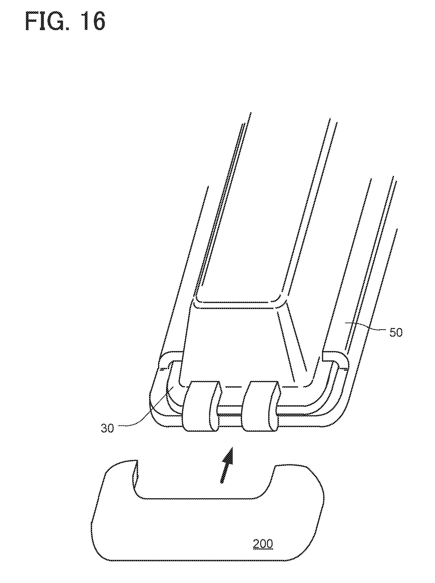
[0070] As shown in FIG. 16, a cap 200 may be equipped to an end of the tank 120, at which the foot portion 30 is partially exposed from the holder portion 50. In this way, the cap 200 entirely surrounds the end of the tank 120. The cap 200 is a bottomed hollow member integrally formed by deep drawing a metallic material. After being mounted to the end of the tank 120, the cap 200 may be compressed downward onto the end of the tank 120. In the present configuration, the end of the tank 120 may be continuously covered by the cap 200 similarly to the other end. In the second embodiment, the tabs 58 may be omitted.
Third Embodiment
[0071] As shown in FIG. 17, a tank part 302 may be inserted-molded with a seal member 308. In this case, a foot portion 330 may have a recess 332 having the cross section in an inverse tapered shape. In the present example, the cross section of the recess 332 is in a ducktail shape. The present configuration may integrate the seal member 308 securely to the foot portion 330.
[0072] During insertion of the foot portion 330 through the slot 50a of the core plate 4, friction may occur between the seal member 308 and the core plate 4. The seal member 308 would potentially deform due to the friction during the insertion. The present configuration may fortify the interface between the seal member 308 and the foot portion 330 and may avoid deformation of the seal member 308 caused by the friction.
Other Embodiment
[0073] The tabs 58 are optional. Provided that the holder portion 50 grips the foot portion 30 and the seal member 8 with sufficient rigidity, the tabs 58 may be omitted.
[0074] The cap 200 may be provided to an end of the tank 120 instead of or in addition to the third holder 56.
[0075] The tank part 2 may be formed of a metallic material such as an aluminum alloy by die-casting or press working.
[0076] The tank may be used for a heat exchanger for various thermal system such as a thermal recovery cycle for a power source and/or a refrigerant cycle.
[0077] While the present disclosure has been described with reference to preferred embodiments thereof, it is to be understood that the disclosure is not limited to the preferred embodiments and constructions. The present disclosure is intended to cover various modification and equivalent arrangements. In addition, while the various combinations and configurations, which are preferred, other combinations and configurations, including more, less or only a single element, are also within the spirit and scope of the present disclosure.
* * * * *
D00000
D00001
D00002
D00003
D00004
D00005
D00006
D00007
D00008
D00009
D00010
D00011
D00012
D00013
D00014

XML
uspto.report is an independent third-party trademark research tool that is not affiliated, endorsed, or sponsored by the United States Patent and Trademark Office (USPTO) or any other governmental organization. The information provided by uspto.report is based on publicly available data at the time of writing and is intended for informational purposes only.
While we strive to provide accurate and up-to-date information, we do not guarantee the accuracy, completeness, reliability, or suitability of the information displayed on this site. The use of this site is at your own risk. Any reliance you place on such information is therefore strictly at your own risk.
All official trademark data, including owner information, should be verified by visiting the official USPTO website at www.uspto.gov. This site is not intended to replace professional legal advice and should not be used as a substitute for consulting with a legal professional who is knowledgeable about trademark law.