System For Containment And Organization Of Medical Wire
Mohika; Brian O. ; et al.
U.S. patent application number 16/365901 was filed with the patent office on 2019-07-18 for system for containment and organization of medical wire. This patent application is currently assigned to Cook Medical Technologies LLC. The applicant listed for this patent is Cook Medical Technologies LLC. Invention is credited to John A. Brumleve, Brian O. Mohika.
| Application Number | 20190219079 16/365901 |
| Document ID | / |
| Family ID | 53835928 |
| Filed Date | 2019-07-18 |


| United States Patent Application | 20190219079 |
| Kind Code | A1 |
| Mohika; Brian O. ; et al. | July 18, 2019 |
SYSTEM FOR CONTAINMENT AND ORGANIZATION OF MEDICAL WIRE
Abstract
A system for containment and organization of a medical wire features a clamp. A first ridged and grooved clamping block is located on a clamp first side posterior end and a second ridged and grooved clamping block is located on a clamp second side posterior end. A first side compression member is located on an inside surface of a clamp first side and a second side compression member is located on an inside surface of the clamp second side. An adjustable ratcheting lock attaches the clamp first side and the clamp second side. A first finger grip is located on an outside surface of the clamp first side and a second finger grip is located on an outside surface of the clamp second side. A Medical wire is placed between the first side compression member and the second side compression member then the clamp is compressed against the medical wire.
| Inventors: | Mohika; Brian O.; (Lawrence, MA) ; Brumleve; John A.; (Bloomington, IN) | ||||||||||
| Applicant: |
|
||||||||||
|---|---|---|---|---|---|---|---|---|---|---|---|
| Assignee: | Cook Medical Technologies
LLC Bloomington IN |
||||||||||
| Family ID: | 53835928 | ||||||||||
| Appl. No.: | 16/365901 | ||||||||||
| Filed: | March 27, 2019 |
Related U.S. Patent Documents
| Application Number | Filing Date | Patent Number | ||
|---|---|---|---|---|
| 15581901 | Apr 28, 2017 | 10280955 | ||
| 16365901 | ||||
| 14808659 | Jul 24, 2015 | 9664213 | ||
| 15581901 | ||||
| 14512939 | Oct 13, 2014 | 9499318 | ||
| 14808659 | ||||
| 62040305 | Aug 21, 2014 | |||
| Current U.S. Class: | 1/1 |
| Current CPC Class: | B65D 67/02 20130101; Y10T 24/44556 20150115; A61B 90/90 20160201; Y10T 24/44564 20150115; Y10T 24/44444 20150115; A61B 50/20 20160201; A61B 17/0487 20130101; A61B 17/122 20130101; A61B 2017/2825 20130101; A61B 2017/00858 20130101; F16B 2/10 20130101; A61M 25/02 20130101; A61M 2025/024 20130101; A61B 2017/00407 20130101; A61B 90/92 20160201; F16B 2/22 20130101; F16B 2/005 20130101 |
| International Class: | F16B 2/10 20060101 F16B002/10; A61M 25/02 20060101 A61M025/02; A61B 17/122 20060101 A61B017/122; A61B 90/90 20060101 A61B090/90; A61B 50/20 20060101 A61B050/20; A61B 90/92 20060101 A61B090/92; A61B 17/04 20060101 A61B017/04; F16B 2/00 20060101 F16B002/00; B65D 67/02 20060101 B65D067/02; F16B 2/22 20060101 F16B002/22 |
Claims
1. A system for containment and organization of medical wire, wherein the system comprises: a clamp having a first side, a second side, an anterior portion, a posterior end, wherein the first side is coupled to the second side, and wherein the clamp is movable between an open configuration and a closed configuration; a first compression member disposed on an inside surface of the first side, wherein the first compression member is elastomeric and comprises a first surface; and a second compression member disposed on an inside surface of the second side, wherein the second compression member is elastomeric and comprises a second surface, wherein the clamp is configured to receive medical wire between the first compression member and the second compression member such that, when the clamp is moved to the closed configuration, the first compression member and the second compression member are compressed against the medical wire to secure a position of the medical wire within the clamp, and the first surface comprising a surface treatment configured to restrict movement of the medical wire while the clamp is in the closed configuration.
2. The system of claim 1, wherein the first compression member is an open cell foam.
3. The system of claim 2, wherein the surface treatment is a closed cell surface.
4. The system of claim 3, wherein the second surface is a closed cell surface.
5. The system of claim 1, wherein the surface treatment is a plurality of alternating ridges and grooves.
6. The system of claim 5, wherein the second surface comprises a plurality of ridges and grooves configured to interlock with the plurality of ridges and grooves of the first surface when the clamp is in the closed configuration.
7. The system of claim 1, wherein the claim is arranged such that as the claim is moved toward the closed configuration, the first surface of the first compression member and the second surface of the second compression member make substantially planar contact with each other.
8. The system of claim 1, wherein the first compression member and the second compression member each have a rhombic profile.
9. A clamp for containment and organization of medical wire, comprising: a body having a first side, a second side, an anterior end, a posterior end, wherein the first side is coupled to the second side, and wherein the body is movable between an open configuration and a closed configuration; a first compression member disposed on an inside surface of the first side, wherein the first compression member is elastomeric and comprises a first surface; a second compression member disposed on an inside surface of the second side, wherein the second compression member is elastomeric and comprises a second surface, wherein the clamp is configured to receive medical wire between the first compression member and the second compression member such that, when the body is moved to the closed configuration, the first compression member and the second compression member are compressed against the medical wire to secure a position of the medical wire within the clamp; a first finger grip positioned on an outside surface of the first side of the body; and a second finger grip positioned on an outside surface of the second side of the body, wherein the first finger grip and the second finger grip are positioned between the anterior end and the first compression member.
10. The clamp of claim 9, wherein the first compression member has a width which is greater than a width of the first finger grip.
11. The clamp of claim 10, wherein the width of the first finger grip is greater than a width of the body.
12. The clamp of claim 9, wherein the body is biased toward one of the open configuration or the closed configuration.
13. The clamp of claim 9, wherein the first compression member has a thickness which varies from the posterior end extending toward the anterior end.
14. The clamp of claim 13, wherein a compressibility of the first compression member varies from the posterior end extending toward the anterior end according to the thickness of the first compression member.
15. A clamp for containment and organization of medical wire, comprising: a body having a first side, a second side, an anterior end, a posterior end, wherein the first side is coupled to the second side, and wherein the body is movable between an open configuration and a closed configuration; a first compression member disposed on an inside surface of the first side, wherein the first compression member is elastomeric and comprises a first surface; a second compression member disposed on an inside surface of the second side, wherein the second compression member is elastomeric and comprises a second surface, wherein the clamp is configured to receive medical wire between the first compression member and the second compression member such that, when the body is moved to the closed configuration, the first compression member and the second compression member are compressed against the medical wire to secure a position of the medical wire within the clamp, wherein the first compression member and the second compression member are responsive to deform when a force between about 0.25 pounds and 5.0 pounds is applied. compression when closing by force
16. The clamp of claim 15, wherein the body is biased toward the open configuration.
17. The clamp of claim 16, wherein when the body is in the open configuration, a gap is formed between the first compression member and the second compression member at the posterior end, the gap being no wider than 1.7 cm.
18. The clamp of claim 15, wherein the first compression member comprises a width which expands as the compression member extends inwardly from the first side.
19. The clamp of claim 15, further comprising a locking mechanism extending between the first side and the second side of the body, wherein the locking mechanism is configured to maintain the body in the closed configuration.
20. The clamp of claim 19, wherein the locking mechanism is positioned between the anterior end and the first compression member.
Description
CROSS REFERENCE
[0001] This application is a continuation of U.S. patent application Ser. No. 15/581,901 filed Apr. 28, 2017, which is a continuation of U.S. patent application Ser. No. 14/808,659 filed Jul. 24, 2015, now U.S. Pat. No. 9,664,213, which is a continuation-in-part of U.S. patent application Ser. No. 14/512,939 filed Oct. 13, 2014, now U.S. Pat. No. 9,499,318, which claims the benefit of U.S. Provisional Patent Application No. 62/040,305 filed Aug. 21, 2014, the specifications of which are incorporated herein in their entirety by reference.
FIELD
[0002] The present disclosure relates to medical devices, systems, and methods, and more specifically, medical wire devices, medical wire systems, and methods of containing and organizing medical wire.
BACKGROUND
[0003] Wire used for medical purposes is carefully manufactured, sterilized, and sealed in a sterilized package in preparation for use. Once removed from the package, this wire can be difficult to handle and keep separate from other medical wires of a different size, especially in a pressure-filled environment. It can even be slippery at times. The present disclosure features a system and method for containment and organization of medical wire.
[0004] Any feature or combination of features described herein are included within the scope of the present disclosure provided that the features included in any such combination are not mutually inconsistent as will be apparent from the context, this specification, and the knowledge of one of ordinary skill in the art. Additional advantages and aspects are apparent in the following detailed description and claims.
SUMMARY
[0005] The present disclosure features a system for containment and organization of medical wire. In some embodiments, the system comprises a clamp. In some embodiments, the clamp comprises a shape of a "U". In some embodiments, a first ridged and grooved clamping block is angularly located on a clamp first side posterior end and a second ridged and grooved clamping block is angularly located on a clamp second side posterior end. In some embodiments, the first ridged and grooved clamping block interfaces with the second ridged and grooved clamping block upon closure of the clamp.
[0006] In some embodiments, the system comprises a first side compression member. In some embodiments, the first side compression member is located on an inside surface of a clamp first side next to the first ridged and groove clamping block and projects out and away from the clamp first side toward a clamp second side. In some embodiments, the first side compression member comprises a shape of a rectangular prism. In some embodiments, the first side compression member is elastomeric.
[0007] In some embodiments, the system comprises a second side compression member. In some embodiments, the second side compression member is located on an inside surface of the clamp second side next to the second ridged and groove clamping block and projects out and away from the clamp second side toward the clamp first side. In some embodiments, the second side compression member comprises a shape of a rectangular prism. In some embodiments, the second side compression member is elastomeric.
[0008] In some embodiments, the system comprises an adjustable ratcheting lock located between and attaching the clamp first side and the clamp second side. In some embodiments, a ratcheting lock first end is located on the inside surface of the clamp first side between the clamp first side posterior end and a clamp anterior end and a ratcheting lock second end is located on the inside surface of the clamp second side between the clamp second side posterior end and the clamp anterior end.
[0009] In some embodiments, the system comprises a first finger grip located on an outside surface of the clamp first side opposed to the ratcheting lock first end and a second finger grip located on an outside surface of the clamp second side opposed to the ratcheting lock second end.
[0010] In some embodiments, medical wire is placed in an open clamp between the first side compression member and the second side compression member. In some embodiments, the clamp is closed having the first ridged and grooved clamping block interlocked against the second ridged and grooved clamping block. In some embodiments, the adjustable ratcheting lock is tightened via manually pinching the clamp via the first finger grip and the second finger grip to compress the first side compression member and the second side compression member against the medical wire for securely holding into position.
BRIEF DESCRIPTION OF THE DRAWINGS
[0011] FIG. 1 shows a front view of one embodiment of the present invention, in the open position.
[0012] FIG. 2 shows a front view of the embodiment, in the closed position.
[0013] FIG. 3 shows a front view of the embodiment, in the open position, with a medical wire.
[0014] FIG. 4 shows a side view of the embodiment, in the closed position, with a medical wire.
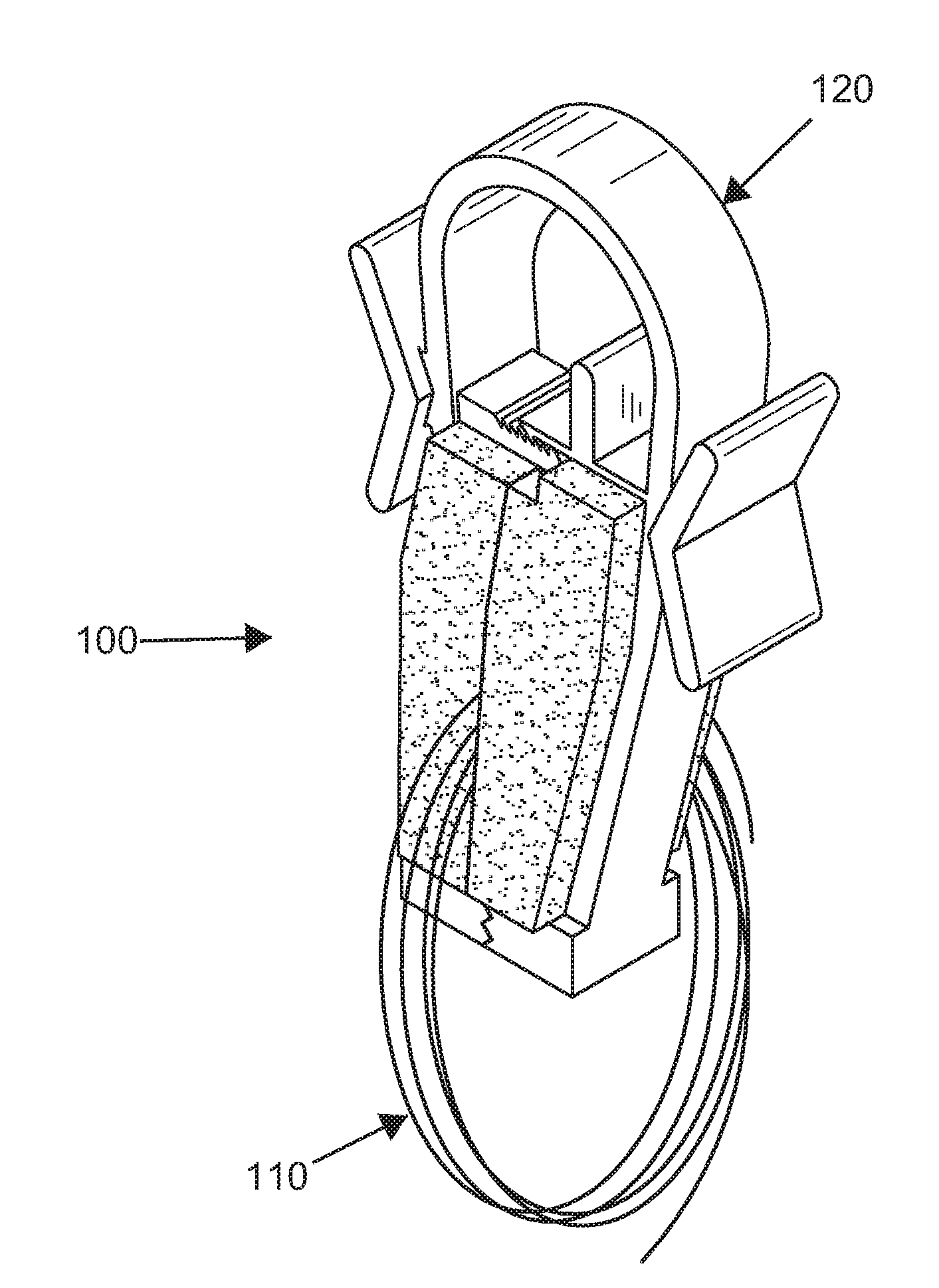
[0015] FIG. 5 shows a perspective view of the embodiment, in the open position.
[0016] FIG. 6 shows a perspective view of the embodiment, in the closed position, with a medical wire.
[0017] FIG. 7 shows a perspective view of another embodiment of a compression member.
[0018] FIG. 8 shows a perspective view of another embodiment of a compression member.
DESCRIPTION OF PREFERRED EMBODIMENTS
[0019] A list of possible elements shown in the drawings and corresponding to elements described below are included herein:
[0020] 100 Medical wire containment and organization system
[0021] 110 Medical wire
[0022] 115 Body
[0023] 120 Clamp
[0024] 121 Clamp first side
[0025] 122 Clamp second side
[0026] 123 Clamp first side posterior end
[0027] 124 Clamp second side posterior end
[0028] 125 Clamp anterior end
[0029] 126 Clamp posterior end
[0030] 131 First ridged and grooved clamping block
[0031] 132 Second ridged and grooved clamping block
[0032] 141 First side compression member
[0033] 142 Second side compression member
[0034] 150 Ratcheting lock
[0035] 151 Ratcheting lock first end
[0036] 152 Ratcheting lock second end
[0037] 161 First finger grip
[0038] 162 Second finger grip
[0039] 170 Gap
[0040] 172 First surface
[0041] 174 Second surface
[0042] 182 Groove
[0043] 184 Ridge
[0044] 190 First material
[0045] 192 Second material
[0046] 194 Minimum width for wedge-shaped compression member
[0047] 196 Maximum width for wedge-shaped compression member
[0048] Referring now to FIG. 1-6, one embodiment of the present invention features a system (100) for containment and organization of medical wire. In some embodiments, the system (100) comprises a clamp (120) having a clamp first side (121), a clamp second side (122), a clamp anterior end (125), and a clamp posterior end (126). In some embodiments, the clamp (120) may comprise a shape of a "U". In some embodiments, the clamp (120) may comprise a terminating clamp first side posterior end (123) located on the clamp first side (121) at the clamp posterior end (126), a terminating clamp second side posterior end (124) located on the clamp second side (122) at the clamp posterior end (126), with the arcuate clamp anterior end (125) joining the clamp first side (121) to the clamp second side (122). In some embodiments, a first ridged and grooved clamping block (131) may be angularly located on the clamp first side posterior end (123) and a second ridged and grooved clamping block (132) may be angularly located on the clamp second side posterior end (124). In some embodiments, the first ridged and grooved clamping block (131) may mate and/or interface with the second ridged and grooved clamping block (132) upon closure of the clamp (120). In some embodiments, the first ridged and grooved clamping block (131) and the second ridged and grooved clamping block (132) may be positioned at a 90 degree angle with respect to the clamp first side (121) and the clamp second side (122), respectively. In some embodiments, the first ridged and grooved clamping block (131) and the second ridged and grooved clamping block (132) may be positioned at a 75 degree angle with respect to the clamp first side (121) and the clamp second side (122), respectively. In some embodiments, the first ridged and grooved clamping block (131) and the second ridged and grooved clamping block (132) may be positioned at a 60 degree angle with respect to the clamp first side (121) and the clamp second side (122), respectively. In some embodiments, the first ridged and grooved clamping block (131) and the second ridged and grooved clamping block (132) may be positioned at a 45 degree angle with respect to the clamp first side (121) and the clamp second side (122), respectively. In some embodiments, the first ridged and grooved clamping block (131) and the second ridged and grooved clamping block (132) may be positioned at a 105 degree angle with respect to the clamp first side (121) and the clamp second side (122), respectively. In some embodiments, the first ridged and grooved clamping block (131) and the second ridged and grooved clamping block (132) may be positioned at a 120 degree angle with respect to the clamp first side (121) and the clamp second side (122), respectively. In some embodiments, the first ridged and grooved clamping block (131) and the second ridged and grooved clamping block (132) may be positioned at a 135 degree angle with respect to the clamp first side (121) and the clamp second side (122), respectively.
[0049] In some embodiments, the system (100) may comprise a first side compression member (141). In some embodiments, the first side compression member (141) may be located on an inside surface of the clamp first side (121) next to the first ridged and grooved clamping block (131) and project out and away from the clamp first side (121) toward the clamp second side (122). In some embodiments, the first side compression member (141) may comprise a shape of a rectangular prism. In some embodiments, the first side compression member (141) may be elastomeric.
[0050] In some embodiments the first side compression member (141) may be constructed of foam. In some embodiments the first side compression member (141) may be constructed of rubber. In some embodiments the first side compression member (141) may be constructed of latex. In some embodiments the first side compression member (141) may comprise a planar interfacing surface.
[0051] In some embodiments, the system (100) may comprise a second side compression member (142). In some embodiments, the second side compression member (142) may be located on an inside surface of the clamp second side (122) next to the second ridged and grooved clamping block (132) and project out and away from the clamp second side (122) toward the clamp first side (121). In some embodiments, the second side compression member (142) may comprise a shape of a rectangular prism. In some embodiments, the second side compression member (142) may be elastomeric.
[0052] In some embodiments the second side compression member (142) may be constructed of foam. In some embodiments the second side compression member (142) may be constructed of rubber. In some embodiments the second side compression member (142) may be constructed of latex. In some embodiments the second side compression member (142) may comprise a planar interfacing surface.
[0053] In some embodiments, the system (100) may comprise an adjustable ratcheting lock (150) located between and attaching the clamp first side (121) and the clamp second side (122) in a releasable manner. In some embodiments, a ratcheting lock first end (151) may be located on the inside surface of the clamp first side (121) between the clamp first side posterior end (123) and the clamp anterior end (125) and a ratcheting lock second end (152) may be located on the inside surface of the clamp second side (122) between the clamp second side posterior end (124) and the clamp anterior end (125). In some embodiments, the adjustable ratcheting lock (150) may comprise a plurality of settings corresponding to a level of compression between the first side compression member (141) and the second side compression member (142).
[0054] In some embodiments, the system (100) may comprise a first finger grip (161) located on an outside surface of the clamp first side (121) opposed to the ratcheting lock first end (151) and a second finger grip (162) located on an outside surface of the clamp second side (122) opposed to the ratcheting lock second end (152).
[0055] In some embodiments, medical wire (110) may be placed in an open clamp (120) between the first side compression member (141) and the second side compression member (142). In some embodiments, the clamp (120) may be closed having the first ridged and grooved clamping block (131) interfacing and interlocked against the second ridged and grooved clamping block (132). In some embodiments, the adjustable ratcheting lock (150) may be tightened via manually pinching the clamp (120) via the first finger grip (161) and the second finger grip (162) to compress the first side compression member (141) and the second side compression member (142) against the medical wire (110) for securely holding the medical wire (110) in position.
[0056] In some embodiments, the first side compression member (141) may be located on the inside surface of the clamp first side (121) and the second side compression member (142) may be located on the inside surface of the clamp second side (122). The compression members (141, 142) may be secured to the first and second sides (121, 122) by an adhesive such as a water resistant adhesive, or a saline compatible adhesive.
[0057] In some embodiments, the first side compression member (141) may be located on the inside surface of the clamp first side (121) and the second side compression member (142) may be located on the inside surface of the clamp second side (122), wherein the compression members (141, 142) are secured to the first and second sides (121, 122) via a mechanical fastening, such as a bolt, staple, or fingers extending from the first and second sides (121, 122).
[0058] In some embodiments, the system (100) may further comprise a medical wire (110).
[0059] In some embodiments, the medical wire (110) may be an interventional procedure wire.
[0060] In some embodiments, the medical wire (110) may be a cardiac catheterizing wire.
[0061] In some embodiments, the medical wire (110) may be a hydrophilic wire.
[0062] In some embodiments, the medical wire (110) may be a micro wire.
[0063] In some embodiments, the medical wire (110) may be a guide wire.
[0064] In some embodiments, the medical wire (110) may be a catheter.
[0065] In some embodiments, the system (100) may further comprise a catheter and guide wire bowl. In some embodiments, the system (100) may further comprise a bowl.
[0066] In some embodiments, the system (100) may further comprise a plurality of clamps (120). In some embodiments, the system (100) may further comprise a plurality of color coded clamps (120). In some embodiments, the system (100) may further comprise a plurality of labeled clamps (120).
[0067] In some embodiments, the system (100) may further comprise an indicator located on each clamp (120) for indicating wire type or size.
[0068] In some embodiments, the indicator may be a unique color.
[0069] A method of containment and organization of a medical wire may comprise obtaining a system (100) for containment and organization of a medical wire comprising a clamp (120) having a clamp first side (121), a clamp second side (122), a clamp anterior end (125), and a clamp posterior end (126). In some embodiments, the clamp (120) may comprise a shape of a "U". In some embodiments, the clamp (120) may comprise a terminating clamp first side posterior end (123) located on the clamp first side (121) at the clamp posterior end (126), a terminating clamp second side posterior end (124) located on the clamp second side (122) at the clamp posterior end (126), with the arcuate clamp anterior end (125) joining the clamp first side (121) to the clamp second side (122). In some embodiments, a first ridged and grooved clamping block (131) may be angularly located on the clamp first side posterior end (123) and a second ridged and grooved clamping block (132) may be angularly located on the clamp second side posterior end (124). In some embodiments, the first ridged and grooved clamping block (131) may mate with and/or interface with the second ridged and grooved clamping block (132) upon closure of the clamp (120). In some embodiments, the system (100) may comprise a first side compression member (141). In some embodiments, the first side compression member (141) may be located on an inside surface of the clamp first side (121) next to the first ridged and grooved clamping block (131) and projects out and away from the clamp first side (121) toward the clamp second side (122). In some embodiments, the first side compression member (141) may comprise a shape of a rectangular prism. In some embodiments, the first side compression member (141) may be elastomeric. In some embodiments, the system (100) may comprise a second side compression member (142). In some embodiments, the second side compression member (142) may be located on an inside surface of the clamp second side (122) next to the second ridged and grooved clamping block (132) and projects out and away from the clamp second side (122) toward the clamp first side (121). In some embodiments, the second side compression member (142) may comprise a shape of a rectangular prism. In some embodiments, the second side compression member (142) may be elastomeric. In some embodiments, the system (100) may comprise an adjustable ratcheting lock (150) located between and releasably attaching the clamp first side (121) and the clamp second side (122). In some embodiments, a ratcheting lock first end (151) may be located on the inside surface of the clamp first side (121) between the clamp first side posterior end (123) and the clamp anterior end (125) and a ratcheting lock second end (152) is located on the inside surface of the clamp second side (122) between the clamp second side posterior end (124) and the clamp anterior end (125). In some embodiments, the system (100) may comprise a first finger grip (161) located on an outside surface of the clamp first side (121) opposed to the ratcheting lock first end (151) and a second finger grip (162) located on an outside surface of the clamp second side (122) opposed to the ratcheting lock second end (152). In some embodiments, the system (100) may comprise a medical wire (110). In some embodiments, the system (100) may comprise a catheter and guide wire bowl.
[0070] In some embodiments, the method may comprise removing the medical wire (110) from its sterile packaging.
[0071] In some embodiments, the method may comprise placing the medical wire (110) in an open clamp (120) between the first side compression member (141) and the second side compression member (142) in either a straight or a looped position having at least one strand of the medical wire (110) in contact with the first side compression member (141) and the second side compression member (142).
[0072] In some embodiments, the method may comprise closing the clamp (120) with the first ridged and grooved clamping block (131) interfacingly interlocked against the second ridged and grooved clamping block (132).
[0073] In some embodiments, the method may comprise tightening the clamp (120) with the adjustable ratcheting lock (150) via manually pinching the clamp (120) via the first finger grip (161) and the second finger grip (162) to compress the first side compression member (141) and the second side compression member (142) against the medical wire (110) for securely holding into position.
[0074] In some embodiments, the method may comprise placing the clamp (120) with the medical wire (110) into the catheter and guide wire bowl in preparation for use.
[0075] In some embodiments, the method may comprise discarding the clamp (120) after a single use.
[0076] In some embodiments, the method may comprise a plurality of clamps (120) used with a plurality of medical wires (110). In some embodiments, the plurality of clamps (120) may comprise a unique indicator located on each clamp (120) for indicating wire type or size. These unique indicators may assist in identifying the each clamp (120) and the associated medical wire (110) restrained by the clamp (120).
[0077] In another embodiment, the clamp (120) may comprise a body (115) having the first side element (121) and the second side element (122). The first side element (121) and the second side element (122) may be connected by an anterior end (125). The body (115) of the clamp (120) may be movable from an open position to a closed position. When the body (115) is in the open position, as shown in FIG. 1, the first side element (121) and the second side element (122) are separated by a gap (170). When the body (115) is in the closed position, as shown in FIG. 2, the first side element (121) and the second side element (122) may be closer together, and may have even closed the gap (170).
[0078] The first compression member (141) may be coupled to the inner surface of the first side element (121), and the second compression member (142) may be coupled to the inner surface of the second side element (122). The first and second compression members (141, 142) may project inwardly from the respective first and second side elements (121, 122), and may comprise a respective first surface (172) and a second surface (174) arranged such that when a medical wire is positioned in the gap (170) between the first surface and the second surface, the body (115) may be moved to the closed position. When or before the body (115) reaches the closed position, at least one of the first and second compression members (141, 142) may deform to accommodate the medical wire (110). This deformation may occur due to compression of one or both of the compression members (141, 142). While the body (115) remains in the closed position, the movement of the medical wire (110) in or out of the clamp (120) may be restricted between the first and second compression members (141, 142). The internal resistance of the first and second compression members (141, 142) to compression or deformation may apply a force to the medical wire (110) to restrict its movement and hold it in place.
[0079] The first and second compression members (141, 142) may be made of a material such that the first and second compression members (141, 142) are responsive to deform when a force between 0.25 pounds and 5.0 pounds is applied.
[0080] The first and second compression members (141, 142) may comprise a foam material, such as a sponge, a rubber material, or some other deformable material. To prevent fragments of the first and second compression members (141, 142) from breaking off and attaching to the medical wire (110), it may be advantageous that the first and second compression members (141, 142) comprise closed cell foam, wherein the empty cells within the foam's interior are not exposed on the first or second surfaces (172, 174). Alternatively, open cell foam may be advantageous where greater deformation of the first and second compression members (141, 142) is needed with less force being applied. In some embodiments, it may be advantageous that the first and second compression members (141, 142) are each made from different materials (190, 192) having different compressive abilities, as shown in FIG. 7. Such an embodiment may be useful where, for example, it is desirable that the medical wire (110) should be forced closer to the first side element (121) or second side element (122) when the body (115) is placed in the closed position.
[0081] The first and second compression members (141, 142) may be arranged on the inner surface of the respective first and second side elements (121, 122) projecting inwardly to a maximum thickness. This thickness may be between about 0.3 cm and 1.5 cm. Compression members (141, 142) having greater thickness may be advantageous to allow for greater deformation or compression when receiving the medical wire (110) and therefore, maintain a better grip on the medical wire (110) contained between the compression members (141, 142). The thickness of the compression members (141, 142) may be limited so that they do not completely occlude the gap (170) when the body (115) is in the open position, so that the medical wire (110) may still be easily moved between the first and second compression members (141, 142) while the body (115) is in the open position.
[0082] The first and second compression members (141, 142) may also have a width between about 0.3 cm and 1.4 cm. Compression members (141, 142) having greater width may be able to better secure the medical wire (110). Therefore, it may be advantageous that the compression members (141, 142) have a width which exceeds the width of the first and second side elements (121, 122). Alternatively, it may be desirable that the compression members (141, 142) have a "wedge-shape", wherein the width expands as the compression member (141, 142) extends inwardly, as shown in FIG. 8. In such an embodiment, the width of the first and second surfaces (172, 174) may define the maximum width (196) of the compression members (141, 142).
[0083] The thickness of the first and second compression members (141, 142) may vary from the posterior end to the anterior end of the compression members (141, 142). Such variation may be advantageous to allow the surfaces (172, 174) of the compression members (141, 142) to be substantially coplanar when the body (115) is placed in the closed position. Accordingly, the gap (170) between the compression members (141, 142) while the body (115) is in the open position may also vary. For embodiments similar to FIG. 1, the gap (170) is likely to be larger on the posterior side of the compression members (141, 142), and smaller on the anterior side of the compression members (141, 142). The size of the gap may vary between about 0.1 cm and 1.7 cm. Similarly, the thickness of the compression members (141, 142) may vary from the posterior end to the anterior of the compression members (141, 142). As shown in FIG. 1, the anterior end of the compression members (141, 142) may have the maximum thickness and the posterior end of the compression members (141, 142) may have the minimum thickness. The compressibility of the compression members (141, 142) may vary according to the thickness of the compression members (141, 142).
[0084] Additionally, it may be desirable that the first and second compression members (141, 142) have different widths, so that when the first and second compression members (141, 142) contact one another, the wider of the first and second surfaces (172, 174) covers the entire width of the narrower of the first and second surfaces (172, 174). The wider of the first and second surfaces may also extend beyond the width of the narrower surface (172, 174). Therefore, when body (115) is moved to the closed position so that when the medical wire (110) is restrained between the compression members (141, 142), a first restricting force is directed on the medical wire (110) directed on the portion of the medical wire (110) which overlaps both compression members (141, 142). Additionally, a second force may also be directed to where the medical wire (110) overlaps the portion of the wider surface (172, 174) but not overlapping the narrower surface (172, 174).
[0085] In some embodiments, it may be desirable that at least one of the first and second compression members (141, 142) comprise a plurality of materials (190, 192) stacked inwardly upon each other, where each of the plurality of materials (190, 192) has a different compressibility. For example, an embodiment could comprise one or both compression members (141, 142) having a contacting material (190) which is stacked inward from a base material (192). Depending on the function of the compression members (141, 142) and the characteristics of the medical wire (110) the compression members (141, 142) are configured to receive, one of the materials (190, 192) may have a greater compressibility than the other material (190, 192). In an embodiment where the contacting material (190) has greater compressibility, the compression members (141, 142) may easily conform to the shape of the medical wire (110) when the body (115) is placed in the closed position and resist the movement of the medical wire (110) in the vertical direction as well as the length-wise direction. Alternatively, an embodiment where the base material (192) has greater compressibility may be desirable. Such an arrangement may reduce the amount by which the compression members (141, 142) would conform to the shape of the medical wire (110), however, it may also allow for substantial compression while applying the force of compression more evenly across the first and second surfaces (172, 174) of the compression members (141, 142). This may be desirable where the first and second surfaces (172, 174) are arranged to capture the medical wire (110) in a groove (182) or receiving element. In some embodiments, similar effects as those described above may be accomplished by compression members (141, 142) having more than two materials (190, 192), or by compression members (141, 142) having a compressibility gradient which varies with the thickness of the compression member (141, 142).
[0086] The first and second surfaces (172, 174) may comprise a surface treatment to better capture and restrain the medical wire (110) while the body (115) is in the closed position. The surface treatment may be a coating with a material having a high coefficient of friction, a collection of surface irregularities , such as pits and projections, arranged on the first and second surfaces (172, 174), or a series of grooves (184) and ridges (182) arranged along a portion of the first and second surfaces (172, 174).
[0087] One of the first or second surfaces (172, 174) may comprise a series of grooves (184) and ridges (182). The other of the first and second surfaces (172, 174) may be flat, or may comprise another series of grooves (184) and ridges (182). Where there are grooves (184) and ridges (182) on both the first and second surfaces (172, 174), it may be desirable that these grooves (184) interlock, causing the gap (170) to be completely closed when the body (115) is placed in the closed position. The medical wire (110) may be placed within the clamp (120) spanning the width of the first and second surfaces (172, 174). The grooves (184) and ridges (182) alternatively may be arranged to span the length or a portion of the length of the first or second surface (172, 174) to apply the force of compression to focused areas of the medical wire (110), as shown in FIG. 7. Alternatively, the grooves (184) and ridges (182) may be arranged to span the width or a portion of the width of the first and second surfaces (172, 174) to capture the medical wire (110) within the groove (184) and restrain the lengthwise movement of the medical wire (110), as shown in FIG. 8. Additionally, where the grooves (184) and ridges (182) are arranged spanning the width of the first and second surfaces (172, 174), it may be desirable that the grooves (184) and ridges (182) are arranged in a planform arc across the width of the first and second surfaces (172, 174) so that the coiled medical wire (110) may be accommodated within the grooves (184). Furthermore, it may be desirable that the grooves (184) and ridges (182) have varying arcs to accommodate coils of medical wires (110) having varying diameters.
[0088] As discussed above, some embodiments of the clamp (120) may comprise clamping blocks (123, 124) extending inwardly from the posterior end of the first and second side elements (121, 122). The clamping blocks (123, 124) may be made of a substantially rigid material and the inward end of each clamping block (123, 124) may be in contact when the body (115) is moved to the closed position. The inward end of each clamping block (123, 124) may define the limit of the movement of the body (115) to the closed position. While the body (115) is in the closed position, the clamping blocks (123, 124) may define a rigid wall which prevents movement of the medical wire (110) from passing through the posterior end (126) of the clamp (120). To further accomplish this purpose, the inward ends of the clamping blocks (123, 125) may comprise interlocking grooves.
[0089] In some embodiments, at least one of the compression members (141, 142) may extend inward beyond the inward ends of the clamping blocks (123, 124). The result of this arrangement of the compression members (141, 142) is that when the body (115) is moved to the closed position, there will be at least some compression of the compression members (141, 142) even where no medical wire (110) is placed between the compression members (141, 142).
[0090] In some embodiments, it may be desirable that the first and second compression members (141, 142) make substantially planar contact with each other as the body (115) is moved to the closed position. Substantially planar contact may mean that the entirety of the surfaces (172, 174) of the compression members (141, 142) which overlap while the body (115) is in the closed position, come in contact with each other substantially simultaneously as the body (115) is moved to the closed position. An advantage of this may be that such an arrangement may provide even compression between the compression members (141, 142) and may distribute compression evenly across the first and second surfaces (172, 174). Even distribution of the compression of the compression members (141, 142) may more effectively restrain the movement of the medical wire (110) by restraining it in a particular spot between the compression members (141, 142). Alternatively, the compression members (141, 142) may be arranged such that the posterior or anterior ends of the surfaces (172, 174) of the compression members (141, 142) make contact before other areas of the surfaces (172, 174). Such an embodiment may cause unequal compression of the compression members (141, 142) and may be desirable to apply additional force to one of the anterior or posterior ends of the compression member (141, 142) and prevent movement of the medical wire (110) disposed between the compression members (141, 142) in a specific direction.
[0091] In some embodiments, it may be desirable that the body (115) of the clamp (120) is biased to the open position, such that unless force is being applied to the clamp (120), the clamp (120) is able to receive the medical wire (110) between the compression members (141, 142). Furthermore, to restrain the movement of the captured medical wire (110) between the compression members (141, 142) while the body (115) is in the closed position, it may be desirable to include a lock coupled to the body (115) of the clamp (120) to maintain the body (115) in the closed position. The lock may comprise a number of mechanisms adapted to maintain the body (115) in the closed position, such as the ratcheting lock (150) described above. To avoid interfering with the positioning of the medical wire (110) in the gap (170), it may be advantageous to position the lock in a position anterior from the compression members (141, 142).
[0092] As used herein, the term "about" refers to plus or minus 10% of the referenced number.
[0093] Various modifications, in addition to those described herein, will be apparent to those skilled in the art from the foregoing description. Such modifications are also intended to fall within the scope of the appended claims. Each reference cited in the present application is incorporated herein by reference in its entirety.
[0094] Although there has been shown and described the preferred embodiment, it will be readily apparent to those skilled in the art that modifications may be made thereto which do not exceed the scope of the appended claims. Therefore, the scope of the invention is only to be limited by the following claims. Reference numbers recited in the claims are exemplary and for ease of review by the patent office only, and are not limiting in any way. In some embodiments, the figures presented in this patent application are drawn to scale, including the angles, ratios of dimensions, etc. In some embodiments, the figures are representative only and the claims are not limited by the dimensions of the figures. In some embodiments, descriptions using the phrase "comprising" includes embodiments that could be described as "consisting of", and as such the written description requirement for claiming one or more embodiments using the phrase "consisting of" is met.
* * * * *
D00000
D00001
D00002
D00003
D00004
XML
uspto.report is an independent third-party trademark research tool that is not affiliated, endorsed, or sponsored by the United States Patent and Trademark Office (USPTO) or any other governmental organization. The information provided by uspto.report is based on publicly available data at the time of writing and is intended for informational purposes only.
While we strive to provide accurate and up-to-date information, we do not guarantee the accuracy, completeness, reliability, or suitability of the information displayed on this site. The use of this site is at your own risk. Any reliance you place on such information is therefore strictly at your own risk.
All official trademark data, including owner information, should be verified by visiting the official USPTO website at www.uspto.gov. This site is not intended to replace professional legal advice and should not be used as a substitute for consulting with a legal professional who is knowledgeable about trademark law.