Additive Vessel For A Washing Machine Appliance And Related Methods
Wright; Troy Marshall ; et al.
U.S. patent application number 15/869155 was filed with the patent office on 2019-07-18 for additive vessel for a washing machine appliance and related methods. The applicant listed for this patent is Haier US Appliance Solutions, Inc.. Invention is credited to Peter Hans Bensel, Troy Marshall Wright.
| Application Number | 20190218702 15/869155 |
| Document ID | / |
| Family ID | 67212744 |
| Filed Date | 2019-07-18 |


View All Diagrams
| United States Patent Application | 20190218702 |
| Kind Code | A1 |
| Wright; Troy Marshall ; et al. | July 18, 2019 |
ADDITIVE VESSEL FOR A WASHING MACHINE APPLIANCE AND RELATED METHODS
Abstract
A washing machine appliance includes a spray hose assembly fluidly connected to a water supply and configured for selectively providing a flow of wash fluid in a desired direction and location. A receptacle is defined in the spray hose assembly. The receptacle is configured to receive an additive vessel. The washing machine appliance also includes a controller in operative communication with the water supply and the spray hose assembly. The controller may be configured to receive a signal from the spray hose assembly. The signal from the spray hose assembly is indicative of a type of additive in the additive vessel. The controller is also configured to activate the water supply in response to the received signal to provide a flow of water to the spray hose assembly, whereby the flow of water mixes with the additive within the spray hose assembly to form the flow of wash fluid.
| Inventors: | Wright; Troy Marshall; (Louisville, KY) ; Bensel; Peter Hans; (Louisville, KY) | ||||||||||
| Applicant: |
|
||||||||||
|---|---|---|---|---|---|---|---|---|---|---|---|
| Family ID: | 67212744 | ||||||||||
| Appl. No.: | 15/869155 | ||||||||||
| Filed: | January 12, 2018 |
| Current U.S. Class: | 1/1 |
| Current CPC Class: | D06F 39/088 20130101; D06F 2204/086 20130101; D06F 2202/085 20130101; D06F 34/22 20200201; D06F 34/28 20200201; D06F 39/083 20130101; D06F 34/18 20200201; D06F 1/02 20130101; D06F 33/00 20130101; D06F 39/022 20130101; D06F 2202/02 20130101; D06F 39/02 20130101; D06F 39/028 20130101 |
| International Class: | D06F 39/02 20060101 D06F039/02; D06F 39/08 20060101 D06F039/08; D06F 39/00 20060101 D06F039/00; D06F 1/02 20060101 D06F001/02 |
Claims
1. A washing machine appliance comprising: a spray hose assembly fluidly connected to a water supply and configured for selectively providing a flow of wash fluid in a desired direction and location; a receptacle defined in the spray hose assembly, the receptacle configured to receive an additive vessel; and a controller in operative communication with the water supply and the spray hose assembly, the controller configured to activate the water supply to provide a flow of water to the spray hose assembly, whereby the flow of water mixes with the additive within the spray hose assembly to form the flow of wash fluid.
2. The washing machine appliance of claim 1, wherein the controller is further configured to: receive a signal from the spray hose assembly, the signal indicative of a type of additive in the additive vessel; and activate the water supply in response to the received signal to provide the flow of water to the spray hose assembly at a temperature corresponding to the indicated type of additive in the additive vessel.
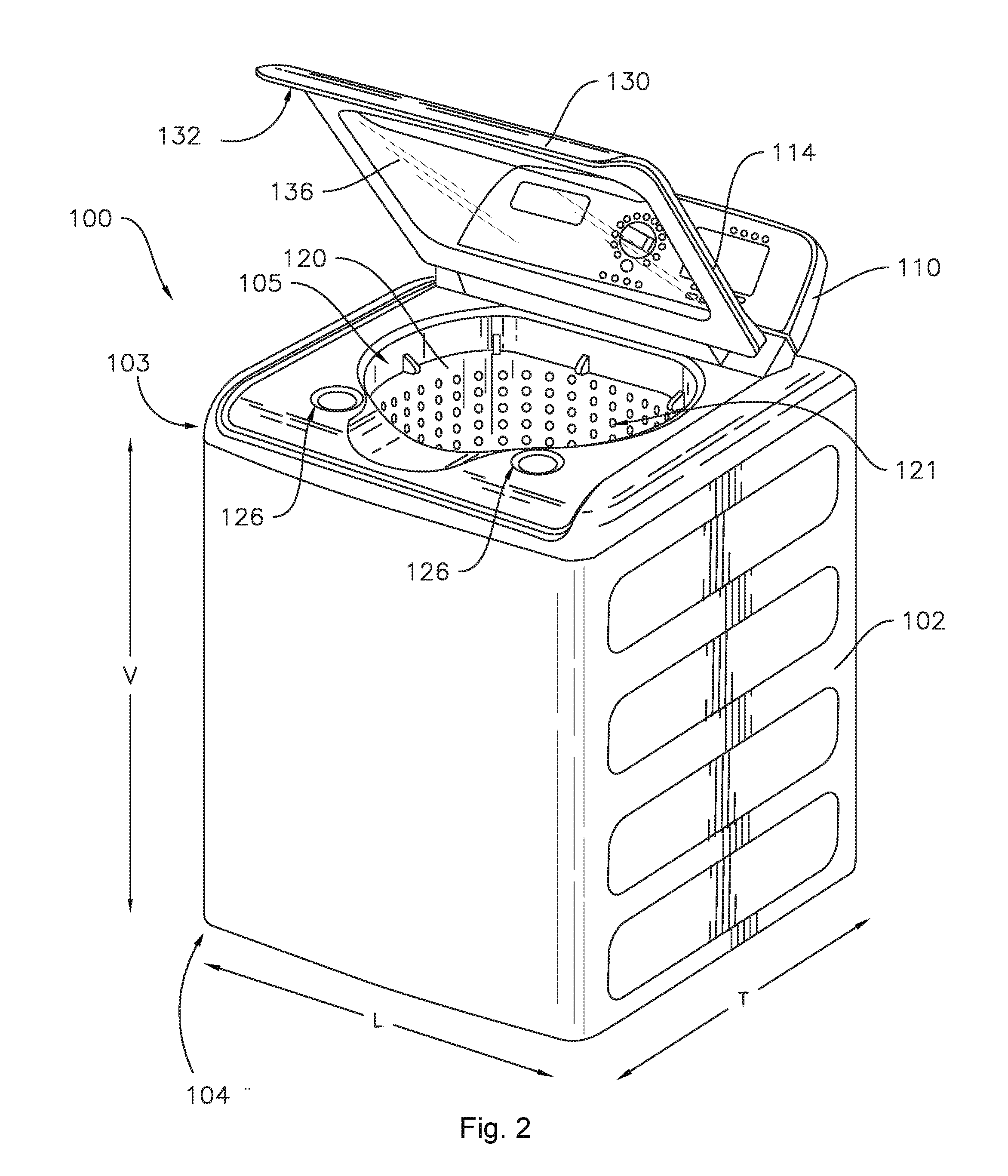
3. The washing machine appliance of claim 2, wherein the receptacle comprises a plurality of electrical contacts and the spray hose assembly is configured to transmit the signal indicative of the type of additive in the additive vessel to the controller when a closed circuit is formed between two of the plurality of electrical contacts.
4. The washing machine appliance of claim 2, wherein the receptacle comprises a plurality of mechanical switches and the spray hose assembly is configured to transmit the signal indicative of the type of additive in the additive vessel to the controller when at least one of the plurality of mechanical switches of the receptacle is actuated.
5. The washing machine appliance of claim 2, wherein the receptacle comprises a plunger and the spray hose assembly is configured to transmit the signal indicative of the type of additive in the additive vessel to the controller in response to a position of the plunger.
6. The washing machine appliance of claim 2, wherein the receptacle comprises a radio-frequency identification tag reader and the spray hose assembly is configured to transmit the signal indicative of the type of additive in the additive vessel to the controller in response to a radio-frequency identification tag on the additive vessel.
7. An additive vessel containing an additive for use in treating laundry articles, the additive vessel comprising: a wall defining an interior volume of the additive vessel, the additive contained within the interior volume; and an additive identifier formed on an exterior surface of the wall, the additive identifier corresponding to a type of the additive contained within the interior volume of the additive vessel.
8. The additive vessel of claim 7, wherein the additive identifier comprises two electrical contacts configured to form a closed circuit with two of a plurality of electrical contacts of a receptacle of a spray hose assembly of a washing machine appliance.
9. The additive vessel of claim 7, wherein the additive identifier comprises a pattern of protrusions configured to actuate selected mechanical switches of a plurality of mechanical switches of a receptacle of a spray hose assembly of a washing machine appliance.
10. The additive vessel of claim 7, wherein the additive identifier comprises an actuator configured to actuate a plunger of a receptacle of a spray hose assembly of a washing machine appliance to a predetermined position.
11. The additive vessel of claim 7, wherein the additive identifier comprises a radio-frequency identification tag.
12. A method of providing a flow of wash fluid to a washing machine appliance, the washing machine appliance comprising a spray hose assembly fluidly connected to a water supply and configured for selectively providing the flow of wash fluid in a desired direction and location, the method comprising: receiving an additive vessel within a receptacle of the spray hose assembly; providing a flow of water to the spray hose assembly; and mixing the flow of water with the additive within the spray hose assembly to form the flow of wash fluid.
13. The method of claim 12, further comprising receiving a signal from the spray hose assembly, the signal indicative of a type of additive in the additive vessel and wherein the step of providing the flow of water to the spray hose assembly comprises providing the flow of water to the spray hose assembly in response to the received signal.
14. The method of claim 13, wherein providing the flow of water comprises providing the flow of water at a temperature corresponding to a type of the additive.
15. The method of claim 13, wherein the receptacle comprises a plurality of electrical contacts and the additive vessel comprises two electrical contacts, wherein receiving the additive vessel within the receptacle comprises forming a closed circuit between the two electrical contacts of the additive vessel and two of the plurality of electrical contacts of the receptacle, the method further comprising transmitting the signal indicative of the type of the additive when the closed circuit is formed.
16. The method of claim 13, wherein the receptacle comprises a plurality of mechanical switches and the additive vessel comprises a pattern of protrusions, wherein receiving the additive vessel within the receptacle comprises actuating selected mechanical switches of the plurality of mechanical switches with the pattern of protrusions, the method further comprising transmitting the signal indicative of the type of the additive based on the actuated mechanical switches.
17. The method of claim 13, wherein the receptacle comprises a plunger and the additive vessel comprises an actuator, wherein receiving the additive vessel within the receptacle comprises actuating the plunger of the receptacle to a predetermined position with the actuator of the additive vessel, the method further comprising transmitting the signal indicative of the type of the additive based on the position of the plunger.
18. The method of claim 13, wherein the receptacle comprises a radio-frequency identification tag reader and the additive vessel comprises a radio-frequency identification tag, wherein receiving the additive vessel within the receptacle comprises positioning the radio-frequency identification tag of the additive vessel proximate to the radio-frequency identification tag reader of the receptacle, the method further comprising transmitting the signal indicative of the type of the additive in response to the radio-frequency identification tag of the additive vessel.
19. The method of claim 12, further comprising puncturing the additive vessel after receiving the additive vessel within the receptacle of the spray hose assembly and prior to providing the flow of water to the spray hose assembly.
20. The method of claim 12, further comprising squeezing the additive vessel after receiving the additive vessel within the receptacle of the spray hose assembly and prior to providing the flow of water to the spray hose assembly.
Description
FIELD OF THE INVENTION
[0001] The present subject matter relates generally to washing machine appliances, and more particularly to accessories for washing machine appliances which provide improved formation and distribution of a wash fluid.
BACKGROUND OF THE INVENTION
[0002] Washing machine appliances generally form a wash fluid to clean clothing articles disposed within a wash basket of the appliance. The wash fluid can include water and various fluid additives, e.g., detergent, fabric softener, and/or bleach. The fluid additives can be mixed with water within a wash tub of the appliance in order to form the wash fluid.
[0003] During operation of certain washing machine appliances, a volume of wash fluid is directed into the tub in order to wash and/or rinse articles within the wash chamber. More specifically, a predetermined volume of wash fluid is typically provided through a stationary nozzle positioned at the center of the back wall of the washing machine appliance. However, in certain situations, a user may wish to have additional wash fluid dispensed into the tub and/or may wish to direct the flow of wash fluid onto a particular garment or within a specific region of the wash tub, e.g., to perform a pretreating operation, to saturate a particular article of clothing, or to accommodate an extra-large load. The ability to adjust the amount of water or wash fluid and its dispensing location is a commercially desirable feature and increases the user's positive perception of the wash process generally.
[0004] To introduce fluid additive into the wash tub, a user can manually add the fluid additive to the wash tub and/or the wash basket. For example, after starting the appliance, the user can pour detergent directly into the wash basket. Conversely, certain washing machine appliances include features for receiving fluid additives and dispensing the fluid additives during operation of the appliance. For example, a tray or container mounted to a top panel of a vertical axis washing machine appliance can receive a fluid additive and direct the fluid additive into a wash tub of the appliance. Similarly, a horizontal axis washing machine appliance can include a drawer with a container mounted therein that receives a fluid additive and directs the fluid additive into a wash tub of the appliance. However, through continuous use, the dispenser cup may build up an undesirable amount of residue from one or more of the fluid additives. The user may be required to remove the dispenser cup, transport the dispenser cup to, e.g., a kitchen sink, and manually wash the dispenser cup in order to remove the undesired residue.
[0005] Accordingly, a washing machine appliance that provides a user with more control over forming and dispensing wash fluid is desirable. For example, a washing machine appliance including one or more features to allow mixing an additive into a flow of water to form a wash fluid and dispensing the flow of wash fluid at any desired location would be useful.
BRIEF DESCRIPTION OF THE INVENTION
[0006] The present invention provides a washing machine with a spray hose assembly for selectively mixing water and additive to create a flow of wash fluid and providing the flow of wash fluid in a desired direction and location. The additive is provided in an additive vessel. The additive vessel may be received within a receptacle in the spray hose assembly and the additive may mix with a flow of water to form the wash fluid in the spray hose assembly. Additional aspects and advantages of the invention will be set forth in part in the following description, or may be apparent from the description, or may be learned through practice of the invention.
[0007] In one exemplary embodiment, a washing machine appliance is provided. The washing machine appliance includes a spray hose assembly fluidly connected to a water supply and configured for selectively providing a flow of wash fluid in a desired direction and location. A receptacle is defined in the spray hose assembly. The receptacle is configured to receive an additive vessel. The washing machine appliance also includes a controller in operative communication with the water supply and the spray hose assembly. The controller is configured to activate the water supply to provide a flow of water to the spray hose assembly, whereby the flow of water mixes with the additive within the spray hose assembly to form the flow of wash fluid.
[0008] In another exemplary embodiment, an additive vessel containing an additive for use in treating laundry articles is provided. The additive vessel includes a wall defining an interior volume of the additive vessel. The additive is contained within the interior volume. The additive vessel also includes an additive identifier formed on an exterior surface of the wall. The additive identifier corresponds to a type of the additive contained within the interior volume of the additive vessel.
[0009] In yet another exemplary embodiment, a method of providing a flow of wash fluid to a washing machine appliance is provided. The washing machine appliance includes a spray hose assembly fluidly connected to a water supply and configured for selectively providing the flow of wash fluid in a desired direction and location. The method includes receiving an additive vessel within a receptacle of the spray hose assembly. The method also includes providing a flow of water to the spray hose assembly and mixing the flow of water with the additive within the spray hose assembly to form the flow of wash fluid.
[0010] These and other features, aspects and advantages of the present invention will become better understood with reference to the following description and appended claims. The accompanying drawings, which are incorporated in and constitute a part of this specification, illustrate embodiments of the invention and, together with the description, serve to explain the principles of the invention.
BRIEF DESCRIPTION OF THE DRAWINGS
[0011] A full and enabling disclosure of the present invention, including the best mode thereof, directed to one of ordinary skill in the art, is set forth in the specification, which makes reference to the appended figures.
[0012] FIG. 1 provides a perspective view of an exemplary washing machine appliance that may incorporate various embodiments of the present subject matter with a door or lid of the washing machine appliance shown in a closed position.
[0013] FIG. 2 provides a perspective view of the exemplary washing machine appliance of FIG. 1 with the door or lid of the washing machine appliance shown in an open position.
[0014] FIG. 3 provides a side cutaway view of the exemplary washing machine appliance of FIG. 1.
[0015] FIG. 4 provides a perspective view of a spray head of a spray hose assembly according to one or more exemplary embodiments of the present subject matter.
[0016] FIG. 5 provides a partially sectioned perspective view of an additive vessel according to one or more exemplary embodiments of the present subject matter.
[0017] FIG. 6 provides a section view of the exemplary spray hose assembly of FIG. 4 according to one or more exemplary embodiments of the present subject matter.
[0018] FIG. 7 provides a section view of the exemplary spray hose assembly of FIG. 4 according to one or more additional exemplary embodiments of the present subject matter.
[0019] FIG. 8 provides a section view of the exemplary spray hose assembly of FIG. 4 according to one or more additional exemplary embodiments of the present subject matter.
[0020] FIG. 9 provides a section view of the exemplary spray hose assembly of FIG. 4 according to one or more additional exemplary embodiments of the present subject matter.
[0021] FIG. 10 provides a top view of an exemplary additive vessel according to one or more exemplary embodiments of the present subject matter.
[0022] FIG. 11 provides a top view of an exemplary additive vessel according to one or more additional exemplary embodiments of the present subject matter.
[0023] FIG. 12 provides a top view of an exemplary additive vessel according to one or more additional exemplary embodiments of the present subject matter.
[0024] FIG. 13 provides a top view of an exemplary additive vessel according to one or more additional exemplary embodiments of the present subject matter.
[0025] FIG. 14 provides a flow chart illustrating a method of providing a flow of wash fluid to a washing machine appliance in accordance with at least one embodiment of the present subject matter.
DETAILED DESCRIPTION
[0026] Reference now will be made in detail to embodiments of the invention, one or more examples of which are illustrated in the drawings. Each example is provided by way of explanation of the invention, not limitation of the invention. In fact, it will be apparent to those skilled in the art that various modifications and variations can be made in the present invention without departing from the scope or spirit of the invention. For instance, features illustrated or described as part of one embodiment can be used with another embodiment to yield a still further embodiment. Thus, it is intended that the present invention covers such modifications and variations as come within the scope of the appended claims and their equivalents.
[0027] FIGS. 1 and 2 illustrate an exemplary embodiment of a vertical axis washing machine appliance 100. In FIG. 1, a lid or door 130 is shown in a closed position. In FIG. 2, door 130 is shown in an open position. While described in the context of a specific embodiment of vertical axis washing machine appliance 100, it will be understood that vertical axis washing machine appliance 100 is provided by way of example only. Other washing machine appliances having different configurations, different appearances, and/or different features may also be utilized with the present subject matter as well, e.g., horizontal axis washing machines.
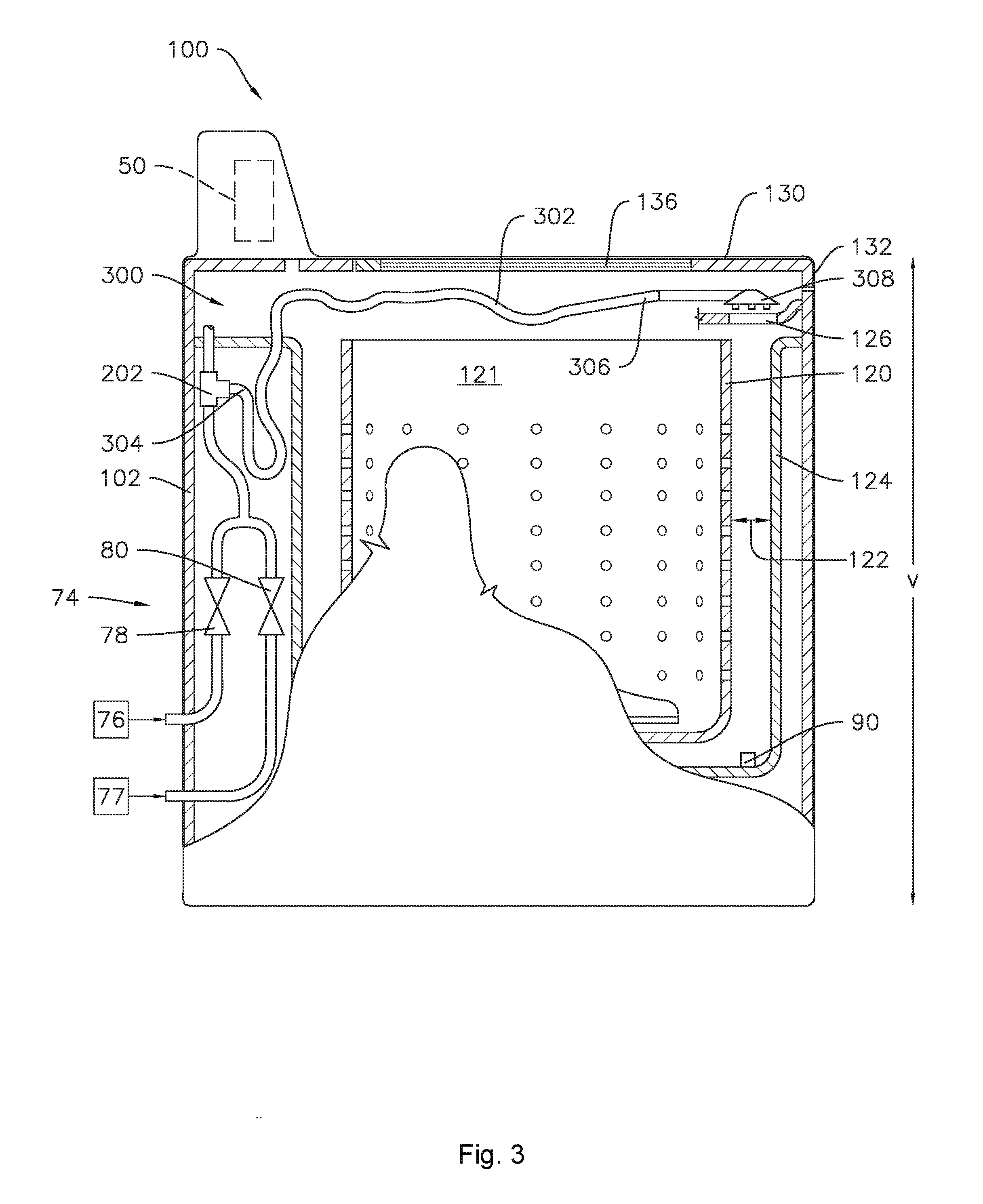
[0028] Washing machine appliance 100 has a cabinet 102 that defines a lateral direction L, a transverse direction T, and a vertical direction V. The lateral direction L, transverse direction T, and vertical direction V are mutually perpendicular and define an orthogonal coordinate system. As shown, cabinet 102 extends between a top 103 and a bottom 104 along the vertical direction V. A wash basket 120 (FIG. 2) is rotatably mounted within cabinet 102. For example, a wash tub 124 (FIG. 3) may mounted within the cabinet 102, as described in more detail below, and the wash basket 120 may be rotatably mounted within the wash tub 124. A motor (not shown) is in mechanical communication with wash basket 120 in order to selectively rotate wash basket 120 (e.g., during an agitation or a rinse cycle of washing machine appliance 100). Wash basket 120 defines a wash chamber 121 (FIG. 2) that is configured for receipt of articles for washing. An agitator or impeller extends from wash basket 120 into wash chamber 121 to assist agitation of articles disposed within wash chamber 121 during operation of washing machine appliance 100.
[0029] Cabinet 102 of washing machine appliance 100 may include an aperture 105 (FIG. 2) that permits user access to wash chamber 121 of wash basket 120. Door 130 is rotatably mounted to the cabinet 102 at or near top 103. In various embodiments, door 130 may be mounted to cabinet 102 or any other suitable support, e.g., door 130 may be mounted to the cabinet 102 at a front portion of the cabinet 102 for a horizontal axis washing machine. Door 130 selectively rotates between the closed position shown in FIG. 1 and the open position shown in FIG. 2. In the closed position, door 130 inhibits access to wash chamber 121. Conversely, in the open position, a user can access wash chamber 121. A window 136 in door 130 permits viewing of wash chamber 121 when door 130 is in the closed position, e.g., during operation of washing machine appliance 100. Door 130 also includes a handle 132 that, e.g., a user may pull and/or lift when opening and closing door 130.
[0030] Cabinet 102 also defines at least one hole or opening 126 (FIG. 2). The opening 126 is configured for receipt of additives, e.g., detergent, fabric softener, and/or bleach. As used herein, the terms "additive" or "fluid additive" generally refer to chemicals other than water, such as detergent, bleach, fabric softener, and/or other such laundry treatment chemicals, which may include solid additives, e.g., in a powder form, or liquid additives or any other suitable form. The opening 126 permits the fluid additive or additives to be delivered into the wash tub 124.
[0031] A control panel 110 with a plurality of input selectors 112 (FIG. 1) extends from the cabinet 102. Control panel 110 and input selectors 112 collectively form a user interface input for operator selection of machine cycles and features. A display 114 of control panel 110 indicates selected features, a countdown timer, and/or other items of interest to appliance users.
[0032] Various sensors may additionally be included in the washing machine appliance 100. For example, a pressure sensor 90 may be positioned in the tub 124 as illustrated. Any suitable pressure sensor 90, such as an electronic sensor, a manometer, or another suitable gauge or sensor may be utilized. The pressure sensor 90 may generally measure the pressure of water in the tub 124. This pressure can then be utilized to estimate the height or level of water in the tub 124. Additionally, a suitable speed sensor (not shown) can be provided to measure rotational speed of basket 120. Other suitable sensors, such as temperature sensors, etc., may additionally be provided in the washing machine appliance 100.
[0033] In an illustrative embodiment, laundry items may be loaded into wash chamber 121 through aperture 105, and washing operation may be initiated through operator manipulation of input selectors 112. Wash basket 120 (and/or wash tub 124 shown in FIG. 3) may be filled with water and detergent to form a wash fluid. One or more valves, e.g., valves 78 and 80, can be controlled by washing machine appliance 100 to provide for filling wash basket 120 to the appropriate level for the amount of articles being washed. Once wash basket 120 is properly filled with fluid, the contents of wash chamber 121 are agitated for cleansing of laundry items in wash basket 120.
[0034] After the agitation phase of the wash cycle is completed, wash basket 120 may be drained. Laundry articles can then be rinsed by again adding fluid to wash basket 120, depending on the particulars of the cleaning cycle selected by a user, impeller may again provide agitation within wash chamber 121. One or more spin cycles may also be used. In particular, a spin cycle may be applied after the wash cycle and/or after the rinse cycle in order to wring wash fluid from the articles being washed. During a spin cycle, wash basket 120 is rotated at relatively high speeds. After articles disposed in wash basket 120 are cleaned and/or washed, the user can remove the articles from wash basket 120, e.g., by reaching into wash chamber 121 through aperture 105.
[0035] Wash tub 124 is configured for containing fluid, e.g., wash and rinse fluids, during operation of washing machine appliance 100 described above. Wash and rinse fluids disposed within wash tub 124 can be used to clean articles disposed in wash basket 120. Wash and rinse fluids can pass between wash basket 120 and wash tub 124 through a plurality of apertures defined by wash basket 120, e.g., during the wash and/or spin cycles described above.
[0036] A water supply 74 of the washing machine appliance 100 may include various valves which may regulate the flow of fluid into and through washing machine appliance 100 from water sources 76 and 77, e.g., water source 76 may include one or more fluid lines, pipes, conduits, etc. which provide hot water to washing machine appliance 100, e.g., from a residential water heater (not shown) and water source 77 may include one or more fluid lines, pipes, conduits, etc. which provide cold water to washing machine appliance 100. For example, a hot water valve 78 and a cold water valve 80 may be positioned in such fluid lines to flow hot water and cold water, respectively, to washing machine appliance 100.
[0037] As illustrated for example in FIG. 3, each valve 78, 80 may be selectively adjusted between an open position allowing a flow of fluid therethrough and a closed position terminating or obstructing the flow of fluid therethrough. Hot water valve 78 may be in fluid communication with hot water source 76, which may be external to the washing machine appliance 100. Similarly, cold water valve 80 may be in fluid communication with cold water source 77, which may also be external to the washing machine appliance 100. The cold water source 77 may, for example, be a commercial water supply, while the hot water source 76 may be, for example, a water heater appliance.
[0038] Referring still to FIG. 3, washing machine appliance 100 further includes a spray hose assembly 300 fluidly connected to the water supply 74 and configured for selectively providing a flow of wash fluid in a desired direction and location. More particularly, for the embodiment depicted, spray hose assembly 300 is fluidly connected to a three-way valve 202 positioned within cabinet 102. Three-way valve 202 is depicted as a T-valve downstream of valves 78, 80. However, in other exemplary embodiments, any suitable three-way valve 202 may be utilized, and further, three-way valve 202 may be attached in any suitable location. For example, in other embodiments, three-way valve 202 may be a Y-valve, and/or may be upstream of valves 78, 80. In the latter embodiment, washing machine appliance 100 may further include two three-way valves, such that a first three-way valve is upstream of hot water valve 78, and a second three-way valve is upstream of cold water valve 80. By being positioned upstream of valves 78, 80, spray hose assembly 300 may provide a flow of water independently from a flow of water provided to other parts of the washing machine appliance 100 (i.e., independently of whether or not valves 78, 80 are open or closed). Alternatively, a single three-way valve may be provided upstream of either hot water valve 78 or cold water valve 80. Notably, in such an embodiment, a spray hose assembly 300 may only provide hot water or cold water, respectively.
[0039] Spray hose assembly 300 includes a hose 302 and a spray head 308. Spray hose assembly 300 is generally configured for providing a flow of wash fluid, e.g., water and/or various additives, into wash tub 124. More specifically, the flow of wash fluid is provided through semi-rigid or flexible hose 302. Flexible hose 302 is generally any fluid conduit that extends from a fluid supply to a location suitable for discharging wash fluid into wash tub 124. In this regard, for example, flexible hose 302 may include an inlet 304 and an outlet 306. Inlet 304 is fluidly connected to a three-way valve 202 for receiving a flow of water. According to an exemplary embodiment, flexible hose 302 may be constructed from any suitably flexible conduit, such as vinyl or rubber. According to the illustrated embodiment, spray head 308 is attached to the outlet 306 of flexible hose 302. Spray head 308 is generally configured for directing the flow of wash fluid in the desired direction, generating the desired spray pattern, or otherwise controlling the flow of wash fluid. For example, as best seen in FIGS. 6 through 9, spray head 308 includes a plurality of outlets 316 through which a wash fluid may be sprayed for directing the flow of wash fluid to desired locations, e.g., in the tub 124, including directly into the wash basket 120, or directly onto a laundry article. In various embodiments, outlets 316 may, for example, be tubes extending from the spray head 308, or alternatively may simply be holes or apertures defined in the spray head 308. However, in other embodiments, outlets 316 may be nozzles or any other suitable openings through which wash fluid may be sprayed. Further, spray head 308 may additionally include other openings, holes, etc. (not shown) through which water may be flowed, i.e., sprayed or poured, into the tub 124 and/or basket 120.
[0040] As illustrated in FIG. 3, the opening 126 may be positioned above wash tub 124 and wash basket 120 (e.g., along the vertical direction V). More particularly, the opening 126 may be positioned directly above a gap 122. Gap 122 is defined between wash tub 124 and wash basket 120 and may correspond to the radial space between wash tub 124 and wash basket 120. In such embodiments, the spray hose assembly 300, and in particular the spray head 308 thereof, may be selectively positionable in or proximate to the opening 126 to provide a flow of water and/or mixed wash fluid into the wash tub 124. In some embodiments a dock (not shown) may be provided to retain the spray head 308 in a docked position where the spray head 308 is docked with the opening 126.
[0041] Operation of washing machine appliance 100 is controlled by a controller or processing device 50 that is operatively coupled to control panel 110 for user manipulation to select washing machine cycles and features. In response to user manipulation of control panel 110, the controller operates the various components of washing machine appliance 100 to execute selected machine cycles and features. The controller 50 may further be in operative communication with (e.g., electrically coupled to) various other components of washing machine appliance 100, such as water supply 74, spray hose assembly 300, pressure sensor 90, and one or more various other suitable sensors, etc. In response to user manipulation of the input selectors 112, controller 50 may operate the various components of washing machine appliance 100 to execute selected machine cycles and features. It should be understood that the controller 50 and the control panel 110 may each be positioned in a variety of locations throughout washing machine appliance 100. Further, it should be understood that a remote interface, such as but not limited to an app running on a smartphone which communicates with the controller 50 wirelessly, e.g., via WIFI or BLUETOOTH, etc., may be provided as well as or instead of the input selectors 112.
[0042] Controller 50 may include a memory and microprocessor, such as a general or special purpose microprocessor operable to execute programming instructions or micro-control code associated with a cleaning cycle. The memory may represent random access memory such as DRAM, or read only memory such as ROM or FLASH. In one embodiment, the processor executes programming instructions stored in memory. For example, the instructions may include a software package configured to execute a portion of the example method 500, described below with reference to FIG. 14. The memory may be a separate component from the processor or may be included onboard within the processor. Alternatively, the controller 50 may be constructed without using a microprocessor, e.g., using a combination of discrete analog and/or digital logic circuitry (such as switches, amplifiers, integrators, comparators, flip-flops, AND gates, and the like) to perform control functionality instead of relying upon software. Control panel 110 and other components of washing machine appliance 100, such as the door 130, water supply 74, and various sensors, etc. may be in communication with controller 50 via one or more signal lines or shared communication busses. It should be noted that controllers 50 as disclosed herein are capable of and may be operable to perform any methods and associated method steps as disclosed herein. For example, in some embodiments, methods disclosed herein may be embodied in programming instructions stored in the memory and executed by the controller 50.
[0043] As illustrated in FIG. 4, the spray head 308 may advantageously have a generally rounded shape. In particular, the spray head 308 may be ergonomically shaped to fit easily in a user's hand, e.g., the spray head 308 may have a teardrop or oblong rounded shape, an example of which is generally illustrated in FIG. 4. As will be described in more detail below in the context of various embodiments, the spray head 308 may include a door 310 which provides selective access to a receptacle 312 (e.g., FIGS. 6-9) configured to receive an additive vessel 400 (e.g., FIGS. 10-13).
[0044] As illustrated in FIG. 5, the additive vessel 400 generally includes a wall 402 at least partially defining an interior volume 404 of the additive vessel 400. An additive A is contained within the interior volume 404. In some embodiments, an additive identifier 406 may be provided on the additive vessel, for example, the additive identifier 406 may be formed on an exterior surface 408 of the wall 402. The additive identifier 406 is depicted schematically in FIG. 5. The additive identifier 406 corresponds to a type of the additive A contained within the interior volume 404 of the additive vessel 400. Various exemplary embodiments of the additive identifier 406 are illustrated in FIGS. 10 through 13 and are described in more detail below.
[0045] FIGS. 6 through 9 illustrate various embodiments of the spray head 308, which may receive the additive vessel 400 within the receptacle 312. In some embodiments, the spray hose assembly 300 may also include various features for detecting the presence of the additive vessel 400 within the receptacle 312 and/or generating and transmitting a signal indicative of the type of additive A contained within the additive vessel 400. In various embodiments, the spray hose assembly 300 may generate and transmit a signal indicative of the presence of an additive vessel 400, a signal indicative of the type of additive A in the vessel 400, or the spray hose assembly 300 may simply receive the additive vessel 400 and provide mixing of the additive A with a flow of water within the spray hose assembly, e.g., within the spray head 308. Although shown in the illustrated examples as provided in the spray head 308, the receptacle 312 may also be provided in any suitable location within the spray assembly 300, e.g., upstream of the spray head 308 with respect to the flow of water from water supply 74. The spray head 308 generally includes a water inlet 314 through which a flow of water W may enter the spray head 308 and an additive aperture 318 through which the additive A may flow from the vessel 400 within the receptacle 312. The water inlet 314 and the additive aperture 318 are both upstream of a mixing chamber 320, where the flow of water W and the additive A may mix within the spray head 308, and in particular within mixing chamber 320 therein, to form a flow of wash fluid F.
[0046] In various example embodiments, the additive vessel 400 may contain a type of additive which is particularly suited for treating a specific type of stain, e.g., blood, grass, chocolate, etc. The type of additive may also be particularly effective at a particular temperature, a particular exposure time, a particular agitation speed, and/or various combinations and ranges thereon. Accordingly, the spray hose assembly 300 may be configured to generate a signal in response to the placement of the additive vessel 400 within the receptacle 312, where the signal is indicative of the type of additive in the additive vessel 400. Further, the controller 50 may be in operative communication with the spray hose assembly 300. The controller 50 may receive the signal from the spray hose assembly 300. In response to the received signal, the controller 50 may activate and/or modify the operation of one or more components of the washing machine appliance 100 based on the type of additive in the additive vessel 400. For example, the controller 50 may activate the water supply 74 in response to the received signal to provide a flow of water W to the spray hose assembly 300, whereby the flow of water W mixes with the additive A within the spray hose assembly 300 to form the flow of wash fluid F. In the foregoing example, activating the water supply 74 may include opening or adjusting a position of one or more of the valves 78, 80, and/or 202. For example, the controller 50 may be configured to activate the water supply 74 by selectively adjusting the position of one or more of the valves 78, 80, and/or 202 to provide the flow of water W to the spray hose assembly 300 at a temperature corresponding to the indicated type of additive A in the additive vessel 400. For example, if the additive A is particularly effective at a high temperature, the controller 50 may provide a flow of hot water from hot water source 76 to the spray head assembly 300 in response to the signal from the spray head assembly 300, e.g., by opening or adjusting valve 76.
[0047] As illustrated for example in FIGS. 6 and 10, in some embodiments, the receptacle 312 may include a plurality of electrical contacts 322 (FIG. 6) and the additive identifier 406 may include two or more mating electrical contacts 410 (FIG. 10) configured to form a closed circuit with at least two of the plurality of electrical contacts 322 of the receptacle 312. For the sake of clarity, only one exemplary electrical contact 322 is illustrated in FIG. 6. One of ordinary skill in the art will understand, however, that any number of electrical contacts 322 may be provided in the plurality of electrical contacts 322, where each electrical contact 322 is substantially duplicative of the illustrated electrical contact 322. Moreover, the structure and function of electrical contacts are generally understood by those of skill in the art and, as such, the electrical contacts 322 are not described in exhaustive detail herein. In embodiments such as the embodiment illustrated in FIG. 6, the spray hose assembly 300 may be configured to transmit the signal indicative of the type of additive A in the additive vessel 400 (FIG. 10) to the controller 50 when the closed circuit is formed between the at least two of the plurality of electrical contacts 322 and the electrical contacts 410 of the additive vessel 400. For example, as shown in FIG. 10, the additive identifier 406 may include two or more electrical contacts 410 with one or more electrically conductive paths 412 between the two or more electrical contacts 410. The two or more electrical contacts 410 of the additive vessel 400 may be configured to form the closed circuit with a selected two of the plurality of electrical contacts 322, e.g., when the additive vessel 400 is placed within the receptacle 312 of the spray hose assembly 300. In such embodiments, the position of the two or more electrical contacts 410 on the additive vessel 400, as well as the conductive path or paths 412 between the electrical contacts 410, may correspond to the type of additive A contained in the additive vessel 400.
[0048] As illustrated for example in FIGS. 7 and 11, in some embodiments, the receptacle 312 may include a plurality of mechanical switches 324 (FIG. 7) and the additive identifier 406 may include a pattern of protrusions 414 (FIG. 11) configured to actuate selected mechanical switches 324 of the plurality of mechanical switches 324. For the sake of clarity, only one exemplary mechanical switch 324 is illustrated in FIG. 7. One of ordinary skill in the art will understand, however, that any number of mechanical switches 324 may be provided in the plurality of mechanical switches 324, where each mechanical switch 324 is substantially duplicative of the illustrated mechanical switch 324. In embodiments such as the example embodiment illustrated in FIG. 7, the spray hose assembly 300 may be configured to transmit the signal indicative of the type of additive A in the additive vessel 400 (FIG. 11) to the controller 50 when at least one of the plurality of mechanical switches 324 in the receptacle 312 is actuated. In some embodiments, the mechanical switches 324 (FIG. 7) may be shaped correspondingly to the one or more projections 414 (FIG. 11) on the additive vessel 400. For example, the projections 414 may be convex, e.g., dome-shaped, and the mechanical switches 324 may have a corresponding concave curvature configured to mate with the dome-shaped projections 414. As illustrated for example in FIG. 11, the additive vessel 400 may include a pattern of projections 414. The particular pattern or arrangement of the projections 414 on the additive vessel 400 may indicate the type of additive within the additive vessel 400. A pattern of projections 414 may include a single projection 414, where the position of the projection 414 on the additive vessel 400 indicates the type of additive A contained within the additive vessel 400. The structure and function of mechanical switches are generally understood by those of skill in the art and, as such, the mechanical switches 324 are not described in exhaustive detail herein.
[0049] As illustrated for example in FIGS. 8 and 12, in some embodiments, the receptacle 312 may include a plunger 326 (FIG. 8) and the additive identifier 406 may include an actuator 416 (FIG. 12) configured to actuate the plunger 326. In embodiments such as the example embodiment illustrated in FIG. 8, the spray hose assembly 300 may be configured to transmit the signal indicative of the type of additive A in the additive vessel 400 to the controller 50 in response to a position of the plunger 326. For example, a position of the actuator 416, e.g., the further to the left as shown in FIG. 12, may depress the plunger 326, e.g., to the left as shown in FIG. 8, a predetermined distance corresponding to the type of the additive A contained within the additive vessel 400. In one example embodiment, the plunger 326 may be operatively connected to a variable resistor (not shown), where the resistance of the variable resistor varies with the linear position of the plunger 326, such that the signal indicative of the type of additive A may be based on the resistance of the variable resistor.
[0050] As illustrated for example in FIGS. 9 and 13, in some embodiments, the receptacle 312 may include a radio-frequency identification tag reader 328 (FIG. 9) and the additive identifier 406 may include a radio-frequency identification tag 418 (FIG. 13). In embodiments such as the example embodiment illustrated in FIG. 9, the spray hose assembly 300 may be configured to transmit the signal indicative of the type of additive A in the additive vessel 400 to the controller 50 in response to the radio-frequency identification tag 418 on the additive vessel 400.
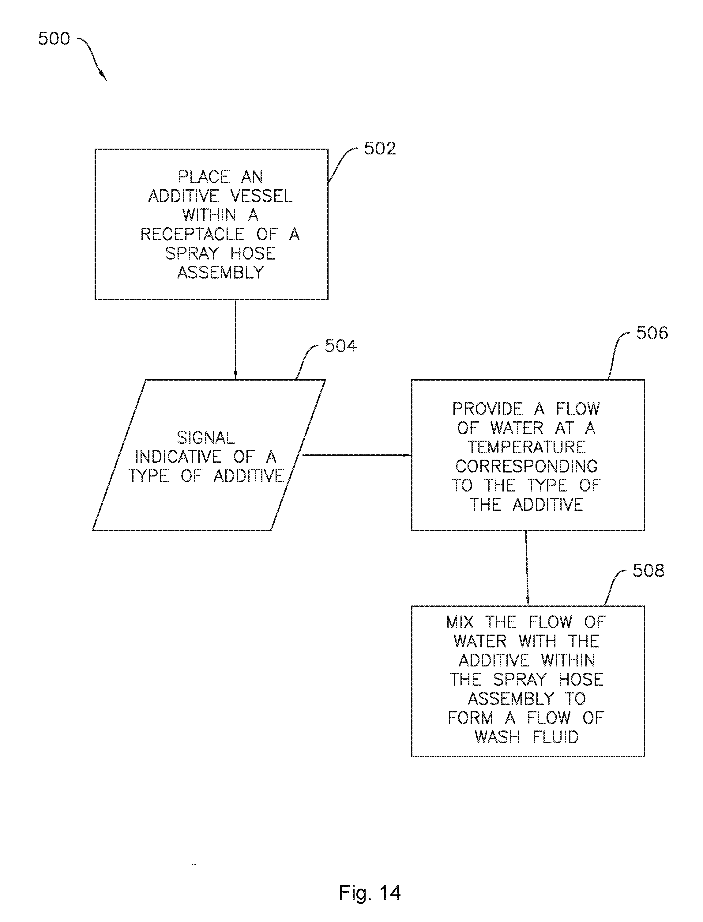
[0051] FIG. 14 illustrates an exemplary method 500 of providing a flow of wash fluid F (e.g., FIGS. 6 through 9) to a washing machine appliance, e.g., the washing machine appliance 100 illustrated in FIGS. 1 through 3. As described above, the washing machine 100 may include a spray hose assembly 300 fluidly connected to a water supply 74 and configured for selectively providing the flow of wash fluid F in a desired direction and location. Turning again to FIG. 14, the method 500 may include a step 502 of placing an additive vessel, e.g., additive vessel 400 as shown in FIGS. 5 and 10 through 13, within a receptacle 312 of the spray hose assembly 300. The method 500 may also include receiving a signal 504 from the spray hose assembly 300, the signal indicative of a type of additive A in the spray hose assembly 300, e.g., contained within the additive vessel 400. In response to the received signal 504, the method 500 may include a step 506 of providing a flow of water W to the spray hose assembly 300. The method 500 may further include mixing the flow of water W with the additive A within the spray hose assembly 300 to form the flow of wash fluid F. In some embodiments, the step 506 of providing the flow of water W may include providing the flow of water W at a temperature corresponding to the type of the additive A.
[0052] In various embodiments, the step 502 of placing the additive vessel 400 in the receptacle 312 may result in transmitting the signal indicative of the type of the additive A. For example, in some embodiments, the receptacle 312 may include a plurality of electrical contacts 322 and the additive vessel 400 may include two electrical contacts 410. In such embodiments, the step 502 of placing the additive vessel 400 within the receptacle 312 may include forming a closed circuit between the two electrical contacts 410 of the additive vessel 400 and two of the plurality of electrical contacts 322 of the receptacle 312, and the method 500 may further include transmitting the signal indicative of the type of the additive A when the closed circuit is formed. As another example, in some embodiments, the receptacle 312 may include a plurality of mechanical switches 324 and the additive vessel 400 may include a pattern of protrusions 414. In such embodiments, the step 502 of placing the additive vessel 400 within the receptacle 312 may include actuating selected mechanical switches 324 of the plurality of mechanical switches 324 with the pattern of protrusions 414, and the method 500 may further include transmitting the signal indicative of the type of the additive based on the actuated mechanical switches 324. As another example, in some embodiments, the receptacle 312 may include a plunger 326 and the additive vessel 400 may include an actuator 416. In such embodiments, the step 502 of placing the additive vessel 400 within the receptacle 312 may include actuating the plunger 326 of the receptacle 312 to a predetermined position with the actuator 416 of the additive vessel 400, and the method 500 may further include transmitting the signal indicative of the type of the additive based on the position of the plunger 326. As another example, in some embodiments, the receptacle 312 may include a radio-frequency identification tag reader 328 and the additive vessel 400 may include a radio-frequency identification tag 418. In such embodiments, the step 502 of placing the additive vessel 400 within the receptacle 312 may include positioning the radio-frequency identification tag 418 of the additive vessel 400 proximate to the radio-frequency identification tag reader 328 of the receptacle 312, and the method 500 may further include transmitting the signal indicative of the type of the additive in response to the radio-frequency identification tag 418 of the additive vessel 400.
[0053] In some embodiments, the additive vessel 400 may comprise a single wall 402, e.g., a cylindrical wall, or the wall 402 may be one of a plurality of walls. For example, as illustrated in FIG. 5, the additive vessel 400 may comprise a cubic or rectangular prism shape including six walls. At least one wall or a portion of a wall of the additive vessel is configured to selectively permit flow of additive A from the additive vessel 400. For example, the wall 402, a portion of the wall 402, or one of the other walls, e.g., as illustrated in FIG. 5, may include a foil material, and the foil material may be punctured to permit the flow of additive A from the additive vessel 400. In other example embodiments, a resealable port or a permeable or soluble membrane may be provided. In some embodiments where a resealable port is provided, the resealable port may be opened by squeezing the vessel 400 and/or by puncturing the resealable port of the additive vessel 400 with a blunt needle. In some example embodiments, the door 310 may be configured to open the additive vessel 400 when the door 310 is closed while the additive vessel 400 is positioned within the receptacle 312. For example, foil material of the additive vessel 400 may be punctured by a needle within the receptacle 312 when the door 310 is closed or the additive vessel 400 may be squeezed by a projection extending into the receptacle 312 from the door 310 to open the resealable port when the door 310 is closed.
[0054] This written description uses examples to disclose the invention, including the best mode, and also to enable any person skilled in the art to practice the invention, including making and using any devices or systems and performing any incorporated methods. The patentable scope of the invention is defined by the claims, and may include other examples that occur to those skilled in the art. Such other examples are intended to be within the scope of the claims if they include structural elements that do not differ from the literal language of the claims, or if they include equivalent structural elements with insubstantial differences from the literal languages of the claims.
* * * * *
D00000
D00001
D00002
D00003
D00004
D00005
D00006
D00007
D00008
D00009
D00010
D00011
XML
uspto.report is an independent third-party trademark research tool that is not affiliated, endorsed, or sponsored by the United States Patent and Trademark Office (USPTO) or any other governmental organization. The information provided by uspto.report is based on publicly available data at the time of writing and is intended for informational purposes only.
While we strive to provide accurate and up-to-date information, we do not guarantee the accuracy, completeness, reliability, or suitability of the information displayed on this site. The use of this site is at your own risk. Any reliance you place on such information is therefore strictly at your own risk.
All official trademark data, including owner information, should be verified by visiting the official USPTO website at www.uspto.gov. This site is not intended to replace professional legal advice and should not be used as a substitute for consulting with a legal professional who is knowledgeable about trademark law.