Water Electrolysis System
NODA; Akihiro ; et al.
U.S. patent application number 16/246874 was filed with the patent office on 2019-07-18 for water electrolysis system. The applicant listed for this patent is HONDA MOTOR CO., LTD.. Invention is credited to Tadashi NISHIYAMA, Akihiro NODA, Hiroshi SHINKAI.
| Application Number | 20190218676 16/246874 |
| Document ID | / |
| Family ID | 67212738 |
| Filed Date | 2019-07-18 |


| United States Patent Application | 20190218676 |
| Kind Code | A1 |
| NODA; Akihiro ; et al. | July 18, 2019 |
WATER ELECTROLYSIS SYSTEM
Abstract
A water electrolysis system includes a water electrolysis stack, a gas-liquid separator, a water supply path, a water introduction unit, a water lead-out unit, a water discharge path, and a circulation pump. The water lead-out unit includes a first water lead-out unit and a second water lead-out unit, which are provided in the water electrolysis stack. The water introduction unit is positioned in a stacking direction between the first water lead-out unit and the second water lead-out unit, together with being disposed in a water electrolysis cell which is positioned between both ends in the stacking direction among a plurality of the water electrolysis cells.
| Inventors: | NODA; Akihiro; (WAKO-SHI, JP) ; NISHIYAMA; Tadashi; (WAKO-SHI, JP) ; SHINKAI; Hiroshi; (WAKO-SHI, JP) | ||||||||||
| Applicant: |
|
||||||||||
|---|---|---|---|---|---|---|---|---|---|---|---|
| Family ID: | 67212738 | ||||||||||
| Appl. No.: | 16/246874 | ||||||||||
| Filed: | January 14, 2019 |
| Current U.S. Class: | 1/1 |
| Current CPC Class: | C25B 15/02 20130101; C25B 9/20 20130101; C25B 15/08 20130101; C25B 1/08 20130101 |
| International Class: | C25B 15/08 20060101 C25B015/08; C25B 9/20 20060101 C25B009/20; C25B 1/08 20060101 C25B001/08; C25B 15/02 20060101 C25B015/02 |
Foreign Application Data
| Date | Code | Application Number |
|---|---|---|
| Jan 15, 2018 | JP | 2018-003968 |
Claims
1. A water electrolysis system equipped with a water electrolysis stack provided with a water introduction unit and a water lead-out unit, and in which a plurality of water electrolysis cells, which produce hydrogen and oxygen by electrolysis of water, are stacked together mutually, and a circulation pump through which water is circulated in a manner so that water which is stored in a gas-liquid separator is supplied from the water introduction unit into the water electrolysis stack via a water supply path, and so that unreacted water which was not subjected to electrolysis inside the water electrolysis stack is discharged from the water lead-out unit into the gas-liquid separator via a water discharge path; wherein the water lead-out unit comprises: a first water lead-out unit provided on one end side of the water electrolysis stack in a stacking direction of the water electrolysis cells; and a second water lead-out unit provided on another end side of the water electrolysis stack in the stacking direction; wherein the water introduction unit is positioned in the stacking direction between the first water lead-out unit and the second water lead-out unit, together with being disposed in a water electrolysis cell which is positioned between both ends in the stacking direction among the plurality of water electrolysis cells.
2. The water electrolysis system according to claim 1, wherein the water introduction unit is disposed in a water electrolysis cell which is located in a central region in the stacking direction among the plurality of water electrolysis cells.
3. The water electrolysis system according to claim 1, wherein, in each of the water electrolysis cells, there are formed: a water introducing communication passage adapted to allow the water introduced from the water introduction unit to flow in the stacking direction; and a water lead-out communication passage adapted to allow the unreacted water which was not subjected to electrolysis to flow in the stacking direction, and to guide the unreacted water to the first water lead-out unit and the second water lead-out unit.
4. The water electrolysis system according to claim 1, wherein each of the first water lead-out unit and the second water lead-out unit is disposed at a position which is shifted in phase from the water introduction unit by 180.degree. in a circumferential direction of the water electrolysis stack.
5. The water electrolysis system according to claim 1, wherein: the first water lead-out unit is provided in a water electrolysis cell positioned at one end in the stacking direction among the plurality of water electrolysis cells; and the second water lead-out unit is provided in a water electrolysis cell position at another end in the stacking direction among the plurality of water electrolysis cells.
6. The water electrolysis system according to claim 1, further comprising: a drain flow passage connected to a lowermost part of the water discharge path; and an opening-closing valve adapted to open and close the drain flow passage; wherein the water electrolysis stack is installed in a manner so that the stacking direction is arranged along a vertical direction; and the second water lead-out unit is positioned lower than the first water lead-out unit and the water introduction unit.
7. The water electrolysis system according to claim 6, wherein the second water lead-out unit is positioned lower than each of the gas-liquid separator, the water supply path, and the circulation pump.
8. The water electrolysis system according to claim 6, wherein the opening-closing valve is a solenoid valve, the water electrolysis system further comprising: an air supply path through which air is supplied to the gas-liquid separator; an air supplying device provided in the air supply path; a freeze prediction unit adapted to predict freezing of the water inside the water electrolysis system; and a control unit adapted to control the solenoid valve and the air supplying device; wherein, when performing a process to stop driving of the water electrolysis system, in the case it is predicted by the freeze prediction unit that there is a possibility that the water inside the water electrolysis system may become frozen, the control unit controls the solenoid valve in a manner so as to open the drain flow passage, and controls driving of the air supplying device in a manner so that air is supplied to the gas-liquid separator via the air supply path.
9. The water electrolysis system according to claim 2, wherein the central region is a middle region obtained by dividing the plurality of water electrolysis cells into three equal parts in the stacking direction.
10. The water electrolysis system according to claim 6, wherein the second water lead-out unit is connected to a lowermost part of the water discharge path.
Description
CROSS-REFERENCE TO RELATED APPLICATION
[0001] This application is based upon and claims the benefit of priority from Japanese Patent Application No. 2018-003968 filed on Jan. 15, 2018, the contents of which are incorporated herein by reference.
BACKGROUND OF THE INVENTION
Field of the Invention
[0002] The present invention relates to a water electrolysis system equipped with a water electrolysis stack in which a plurality of water electrolysis cells that generate hydrogen and oxygen by electrolysis of water are stacked.
Description of the Related Art
[0003] In this type of water electrolysis system, for example, in Japanese Laid-Open Patent Publication No. 2015-113496, a structure is disclosed in which water is supplied to an end plate positioned at an end portion in a stacking direction of the plurality of water electrolysis cells in the water hydrolysis stack.
SUMMARY OF THE INVENTION
[0004] Incidentally, the water electrolysis cells generate heat due to carrying out electrolysis of water therein. Therefore, during a time when the water electrolysis stack is in operation, it is likely for the water electrolysis cells (hereinafter referred to as central water electrolysis cells) which are located at a central portion in the stacking direction of the plurality of water electrolysis cells to be heated to a higher temperature than the water electrolysis cells that are positioned at the ends.
[0005] However, in the above-described conventional technique, since the water is supplied to the end plate, it is impossible to effectively cool the central water electrolysis cells. Accordingly, a temperature difference between the plurality of water electrolysis cells becomes large, and there is a concern that variations may occur in the performance and durability of the respective water electrolysis cells.
[0006] The present invention has been devised taking into consideration the aforementioned problem, and has the object of providing a water electrolysis system in which, by reducing a difference in temperature between a plurality of water electrolysis cells, it is possible to suppress variations in the performance and durability of the respective water electrolysis cells.
[0007] In order to achieve the aforementioned object, a water electrolysis system according to the present invention is equipped with a water electrolysis stack provided with a water introduction unit and a water lead-out unit, and in which a plurality of water electrolysis cells, which produce hydrogen and oxygen by electrolysis of water, are stacked together mutually, and a circulation pump through which water is circulated in a manner so that water which is stored in a gas-liquid separator is supplied from the water introduction unit in the water electrolysis stack via a water supply path, and so that unreacted water which was not subjected to electrolysis inside the water electrolysis stack is discharged from the water lead-out unit into the gas-liquid separator via a water discharge path, wherein the water lead-out unit comprises a first water lead-out unit provided on one end side of the water electrolysis stack in a stacking direction of the water electrolysis cells, and a second water lead-out unit provided on another end side of the water electrolysis stack in the stacking direction, wherein the water introduction unit is positioned in the stacking direction between the first water lead-out unit and the second water lead-out unit, together with being disposed in a water electrolysis cell which is positioned between both ends in the stacking direction among the plurality of water electrolysis cells.
[0008] In accordance with such a configuration, since the water is introduced from the water introduction unit into the water electrolysis cell which is positioned in the stacking direction between the end portions of the plurality of water electrolysis cells, it is possible for the centrally located water electrolysis cells to be cooled effectively. Further, unreacted water which has not been subjected to electrolysis, and to which heat has been imparted accompanying the occurrence of electrolysis taking place in each of the water electrolysis cells, is led out from the first water lead-out unit and the second water lead-out unit positioned at both end sides in the stacking direction of the water electrolysis stack. Therefore, since the temperature difference between the plurality of water electrolysis cells can be reduced, variations in the performance and durability of the respective water electrolysis cells can be suppressed.
[0009] In the above-described water electrolysis system, the water introduction unit may be disposed in a water electrolysis cell which is located in a central region in the stacking direction among the plurality of water electrolysis cells.
[0010] In accordance with such a configuration, the difference in temperature between the plurality of water electrolysis cells can be further reduced.
[0011] In the above-described water electrolysis system, in each of the water electrolysis cells, there may be formed a water introducing communication passage adapted to allow the water introduced from the water introduction unit to flow in the stacking direction, and a water lead-out communication passage adapted to allow the unreacted water which was not subjected to electrolysis to flow in the stacking direction, and to guide the unreacted water to the first water lead-out unit and the second water lead-out unit.
[0012] In accordance with such a configuration, it is possible to cause the water to flow and circulate efficiently in each of the water electrolysis cells.
[0013] In the above-described water electrolysis system, each of the first water lead-out unit and the second water lead-out unit may be disposed at a position which is shifted in phase from the water introduction unit by 180.degree. in a circumferential direction of the water electrolysis stack.
[0014] In accordance with such a configuration, it is possible to cause the water to flow and circulate more efficiently in each of the water electrolysis cells.
[0015] In the above-described water electrolysis system, the first water lead-out unit may be provided in a water electrolysis cell positioned at one end in the stacking direction among the plurality of water electrolysis cells, and the second water lead-out unit may be provided in a water electrolysis cell position at another end in the stacking direction among the plurality of water electrolysis cells.
[0016] In accordance with such a configuration, the difference in temperature between the plurality of water electrolysis cells can be even further reduced.
[0017] In the above-described water electrolysis system, there may further be provided a drain flow passage connected to a lowermost part of the water discharge path, and an opening-closing valve adapted to open and close the drain flow passage, wherein the water electrolysis stack may be installed in a manner so that the stacking direction is arranged along a vertical direction, and the second water lead-out unit is positioned lower than the first water lead-out unit and the water introduction unit.
[0018] In accordance with such a configuration, by opening the opening-closing valve, the water in the water electrolysis stack can be discharged to the exterior of the water electrolysis system via the drain flow passage. Consequently, when driving of the water electrolysis system is shut down, it is possible to prevent water inside the water electrolysis stack from freezing and damaging the water electrolysis stack.
[0019] In the above-described water electrolysis system, the second water lead-out unit may be positioned lower than each of the gas-liquid separator, the water supply path, and the circulation pump.
[0020] In accordance with such a configuration, by opening the opening-closing valve, water in the gas-liquid separator, the water supply path, the circulation pump, and the water discharge path (hereinafter referred to as a water circulation circuit) can be discharged to the exterior of the water electrolysis system. Consequently, when driving of the water electrolysis system is shut down, it is possible to prevent water inside the water circulation circuit from freezing and causing damage to the members that constitute the water circulation circuit.
[0021] In the above-describe water electrolysis system, the opening-closing valve may be a solenoid valve, and the water electrolysis system may further comprise an air supply path through which air is supplied to the gas-liquid separator, an air supplying device provided in the air supply path, a freeze prediction unit adapted to predict freezing of the water inside the water electrolysis system, and a control unit adapted to control the solenoid valve and the air supplying device, wherein, when performing a process to stop driving of the water electrolysis system, in the case it is predicted by the freeze prediction unit that there is a possibility that the water inside the water electrolysis system may become frozen, the control unit may control the solenoid valve in a manner so as to open the drain flow passage, and may control driving of the air supplying device in a manner so that air is supplied to the gas-liquid separator via the air supply path.
[0022] In accordance with such a configuration, by the air that is supplied from the air supplying device, the water inside the water circulation circuit and the water electrolysis stack can be discharged efficiently to the exterior of the water electrolysis system via the drain flow passage. Further, it is possible to shorten the time required for the process to stop driving of the water electrolysis system.
[0023] In the above-described water electrolysis system, the central region may be a middle region obtained by dividing the plurality of water electrolysis cells into three equal parts in the stacking direction.
[0024] In the above-described water electrolysis system, the second water lead-out unit may be connected to a lowermost part of the water discharge path.
[0025] According to the present invention, since the water is introduced from the water introduction unit into a water electrolysis cell which is positioned between both ends in the stacking direction among the plurality of water electrolysis cells, the difference in temperature between the plurality of water electrolysis cells can be made small, so that variations in the performance and durability of the respective water electrolysis cells can be suppressed.
[0026] The above and other objects, features, and advantages of the present invention will become more apparent from the following description when taken in conjunction with the accompanying drawings, in which a preferred embodiment of the present invention is shown by way of illustrative example.
BRIEF DESCRIPTION OF THE DRAWINGS
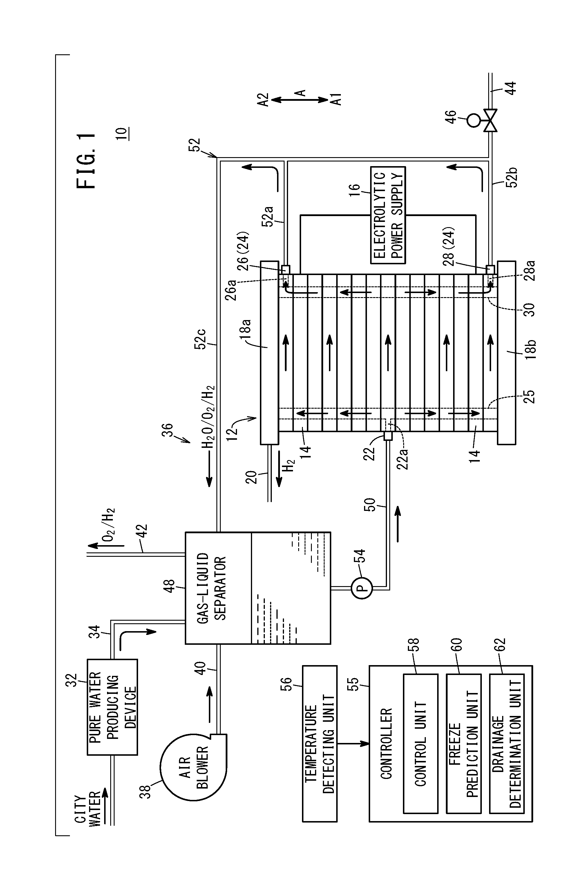
[0027] FIG. 1 is a schematic configuration explanatory diagram of a water electrolysis system according to an embodiment of the present invention;
[0028] FIG. 2 is a flowchart for explaining the freezing preventative operation at a time that the driving of the water electrolysis system is stopped; and
[0029] FIG. 3 is an explanatory diagram of operations of the water electrolysis system shown in FIG. 1.
DESCRIPTION OF THE PREFERRED EMBODIMENTS
[0030] Preferred embodiments of a water electrolysis system according to the present invention will be presented and described below with reference to the accompanying drawings. In FIGS. 1 and 3, the direction of the arrow A1 indicates the direction of gravity, and the direction of the arrow A2 indicates a direction opposite to the direction of gravity.
[0031] As shown in FIG. 1, a water electrolysis system 10 according to an embodiment of the present invention is equipped with a water electrolysis stack 12, which performs electrolysis on pure water (hereinafter, also simply referred to as water) to thereby produce oxygen (at a normal pressure) and hydrogen (at a higher pressure than that of the oxygen).
[0032] The water electrolysis stack 12 has a plurality of mutually stacked water electrolysis cells 14. The water electrolysis cells 14 are formed, for example, in a disk-like shape. Although detailed illustration thereof is omitted, each of the water electrolysis cells 14 includes an electrolyte electrode assembly, for example, a membrane electrode assembly (MEA), and an anode separator and a cathode separator disposed on both sides of the membrane electrode assembly. The membrane electrode assembly includes a solid polymer electrolyte membrane and an anode power supplying member and a cathode power supplying member provided on both sides of the solid polymer electrolyte membrane.
[0033] The water electrolysis stack 12 is installed in a manner so that the stacking direction of the water electrolysis cells 14 lies along the vertical direction (in the direction of the arrow A). An electrolytic power supply 16 which is a DC power source is connected to the water electrolysis stack 12. End plates 18a, 18b are disposed at both ends of the plurality of water electrolysis cells 14 in the stacking direction. A hydrogen lead-out path 20 which communicates with the cathode sides (high-pressure hydrogen generating side) of the respective water electrolysis cells 14 is connected to the upper end plate 18a.
[0034] A water introduction unit 22 and a water lead-out unit 24 are provided in the water electrolysis stack 12. A water inlet port 22a through which water is introduced into the water electrolysis stack 12 is formed in the water introduction unit 22. The water inlet port 22a communicates with a water introducing communication passage 25 which is provided so as to penetrate through the water electrolysis cells 14 in the stacking direction. The water introducing communication passage 25 allows water introduced from the water inlet port 22a of the water introduction unit 22 to flow in the stacking direction. The water introducing communication passage 25 communicates with anode inlet sides (water supply inlet sides) of each of the water electrolysis cells 14.
[0035] The water introduction unit 22 is disposed in a water electrolysis cell 14 which is positioned between both ends (centrally) in the stacking direction among the plurality of water electrolysis cells 14. More specifically, the water introduction unit 22 is disposed in a water electrolysis cell 14 which is positioned in a central region in the stacking direction among the plurality of water electrolysis cells 14. The central region, for example, is a middle region obtained by dividing the plurality of water electrolysis cells 14 into three equal parts in the stacking direction. However, the central region, for example, may be a middle region obtained by dividing the plurality of water electrolysis cells 14 into three parts at a ratio of 1:2:1 in the stacking direction.
[0036] The water lead-out unit 24 includes a first water lead-out unit 26 and a second water lead-out unit 28. The first water lead-out unit 26 is provided in the water electrolysis cell 14 (on an upper end side of the water electrolysis stack 12) located at the upper end (one end) of the plurality of water electrolysis cells 14 in the stacking direction. More specifically, the first water lead-out unit 26 is positioned more upwardly (in the direction of the arrow A2) than the water introduction unit 22. A first water outlet port 26a through which unreacted water (surplus water) which has not been subjected to electrolysis is led out from the interior of the water electrolysis stack 12 is formed in the first water lead-out unit 26.
[0037] The second water lead-out unit 28 is provided in the water electrolysis cell 14 (on a lower end side of the water electrolysis stack 12) located at the lower end (other end) of the plurality of water electrolysis cells 14 in the stacking direction. More specifically, the second water lead-out unit 28 is positioned more downwardly (in the direction of the arrow A1) than the water introduction unit 22 and the first water lead-out unit 26. A second water outlet port 28a through which unreacted water (surplus water) which has not been subjected to electrolysis is led out from the interior of the water electrolysis stack 12 is formed in the second water lead-out unit 28.
[0038] The first water lead-out unit 26 and the second water lead-out unit 28 are disposed at positions, respectively, which are shifted in phase from the water introduction unit 22 by 180.degree. in a circumferential direction of the water electrolysis stack 12. The first water outlet port 26a and the second water outlet port 28a communicate respectively with a water lead-out communication passage 30 which is provided so as to penetrate through the water electrolysis cells 14 in the stacking direction. The water lead-out communication passage 30 communicates with anode outlet sides (water and oxygen discharge sides) of each of the water electrolysis cells 14, allows the unreacted water which has not been subjected to electrolysis to flow in the stacking direction, and guides the unreacted water to the first water lead-out unit 26 and the second water lead-out unit 28.
[0039] The water electrolysis system 10 includes a pure water producing device 32, a pure water supply path 34, a water circulation circuit 36, an air blower 38, an air supply path 40, an air discharge path 42, a drain flow passage 44, and an opening-closing valve 46.
[0040] The pure water producing device 32 produces pure water from city water (tap water). The pure water supply path 34 guides the pure water produced by the pure water producing device 32 to the water circulation circuit 36. The water circulation circuit 36 includes a gas-liquid separator 48, a water supply path 50, a water discharge path 52, and a circulation pump 54. The pure water supply path 34 is connected to an upper part of the gas-liquid separator 48. The gas-liquid separator 48 functions as a tank in which water is stored.
[0041] The water supply path 50 mutually interconnects the bottom portion of the gas-liquid separator 48 and the water introduction unit 22. The water supply path 50 guides the water stored in the gas-liquid separator 48 to the water introduction unit 22. The water discharge path 52 mutually interconnects the first water lead-out unit 26 and the second water lead-out unit 28 respectively to the upper part of the gas-liquid separator 48. The water discharge path 52 guides a mixed fluid, in which unreacted water which has not been subjected to electrolysis, oxygen generated by the reaction, and hydrogen that has permeated from the cathode sides to the anode sides are mixed, into the interior of the gas-liquid separator 48.
[0042] The water discharge path 52 includes a first flow passage portion 52a extending from the first water lead-out unit 26, a second flow passage portion 52b extending from the second water lead-out unit 28, and a third flow passage portion 52c to which the first flow passage portion 52a and the second flow passage portion 52b are respectively connected. The second flow passage portion 52b is positioned lower than the first flow passage portion 52a and the third flow passage portion 52c. Stated otherwise, the second flow passage portion 52b is positioned at a lowermost location of the water discharge path 52.
[0043] The circulation pump 54 is provided in the water supply path 50. The circulation pump 54 circulates the water in a manner so that the water that is stored in the gas-liquid separator 48 is supplied into the interior of the water electrolysis stack 12 from the water introduction unit 22 via the water supply path 50 and further unreacted water which has not been subjected to electrolysis inside the water electrolysis stack 12 is discharged from the water lead-out unit 24 into the gas-liquid separator 48 via the water discharge path 52.
[0044] In the water circulation circuit 36 which is configured in the foregoing manner, the second water lead-out unit 28 is positioned lower than each of the gas-liquid separator 48, the water supply path 50, and the circulation pump 54, together with being connected to the lowermost part (second flow passage portion 52b) of the water discharge path 52.
[0045] The air blower 38 is an air supplying device that guides diluting air into the gas-liquid separator 48 via the air supply path 40. The air supply path 40 and the air discharge path 42 are connected to the upper part of the gas-liquid separator 48. Oxygen and hydrogen inside the gas-liquid separator 48 are discharged into the air discharge path 42 together with the air introduced from the air blower 38.
[0046] The drain flow passage 44 is a flow passage for discharging to the exterior the water in the water circulation circuit 36 and the water electrolysis stack 12, and is connected to the lowermost part (second flow passage portion 52b) of the water discharge path 52. The opening-closing valve 46 is configured in the form of a solenoid valve that opens and closes the drain flow passage 44.
[0047] The water electrolysis system 10 is equipped with a controller 55 that carries out control of operations of the water electrolysis system 10 as a whole. The controller 55 is a computation device including a microcomputer, which includes a CPU (central processing unit), and a ROM, a RAM, and the like, serving as memories. The CPU, by reading and executing programs recorded in the ROM, functions as various function realizing units (function realizing means). The various function realizing units can also be constituted by function realizing devices in the form of hardware.
[0048] Output signals from a temperature detecting unit 56 (temperature sensor) that detects the system environmental temperature are input to the controller 55. The temperature detecting unit 56, for example, detects the temperature of the water in the water supply path 50. However, the temperature detecting unit 56 may also detect the temperature of the water stored in the gas-liquid separator 48.
[0049] The controller 55 comprises a control unit 58, a freeze prediction unit 60, and a drainage determination unit 62. The control unit 58 controls driving and stopping of the circulation pump 54, controls driving and stopping of the air blower 38, and controls the opening and closing operations of the opening-closing valve 46. On the basis of the temperature detected from the temperature detecting unit 56, the freeze prediction unit 60 predicts whether or not there is a possibility that the water inside the water electrolysis system 10 may become frozen. The drainage determination unit 62 determines whether or not all of the water inside the water circulation circuit 36 and the water electrolysis stack 12 has been drained.
[0050] The water electrolysis system 10 which is configured as described above operates in the following manner.
[0051] Under the action of the circulation pump 54, the pure water inside the gas-liquid separator 48 is supplied to the water introduction unit 22 (into the water electrolysis cell 14 positioned roughly in the center in the stacking direction) via the water supply path 50. The pure water supplied to the water introduction unit 22 flows into the water introducing communication passage 25, flows in upward and downward directions (in the stacking direction), and is distributed to the anode inlet sides of each of the water electrolysis cells 14.
[0052] At this time, a voltage is applied to the water electrolysis stack 12 via the electrolytic power supply 16 which is electrically connected thereto. Therefore, in each of the respective water electrolysis cells 14, on the anode sides thereof, pure water is subjected to electrolysis to thereby generate hydrogen ions, electrons, and oxygen. Accordingly, on the cathode sides, hydrogen ions are combined with electrons to obtain hydrogen, and the hydrogen is taken out to the hydrogen lead-out path 20 to thereby become dry hydrogen (product hydrogen), which is supplied to a non-illustrated fuel cell electric vehicle or the like.
[0053] On the other hand, on the anode outlet sides, oxygen produced by the reaction, unreacted water which has not been subjected to electrolysis, and furthermore, the permeated hydrogen flow, and a mixed fluid made up therefrom is led out into the water lead-out communication passage 30, and flows in upward and downward directions (in the stacking direction). The mixed fluid that has flowed upwardly through the water lead-out communication passage 30 is guided into the first flow passage portion 52a via the first water lead-out unit 26. The mixed fluid that has flowed downwardly through the water lead-out communication passage 30 is guided into the second flow passage portion 52b via the second water lead-out unit 28.
[0054] The mixed fluid in the first flow passage portion 52a and the mixed fluid in the second flow passage portion 52b are joined together in the third flow passage portion 52c, are guided into the upper part of the gas-liquid separator 48, and are separated into a liquid (water) and gases (oxygen and hydrogen). Moreover, at this time, the opening-closing valve 46 closes the drain flow passage 44.
[0055] The water that is separated from the mixed fluid is stored in the gas-liquid separator 48, and by action of the circulation pump 54, is guided into the water supply path 50. By action of the air blower 38, the oxygen and hydrogen that are separated from the mixed fluid are discharged to the exterior from the air discharge path 42.
[0056] Next, a description will be given with reference to the flowchart shown in FIG. 2 concerning an operation to prevent freezing at a time that driving of the water electrolysis system 10 is stopped.
[0057] In step S1, the controller 55 receives a signal to stop driving of the water electrolysis stack 12. Upon doing so, the controller 55 stops the application of voltage to the water electrolysis stack 12. Further, in step S2, the freeze prediction unit 60 determines whether there is a possibility that the water inside the water electrolysis system 10 may become frozen. More specifically, the freeze prediction unit 60 determines that there is a possibility of freezing in the case that the temperature (detected temperature) detected by the temperature detecting unit 56 is less than a predetermined temperature (for example, 4.degree. C.), and determines that there is not a possibility of freezing in the case that the detected temperature is greater than or equal to the predetermined temperature.
[0058] If the freeze prediction unit 60 determines that there is not a possibility that the water inside the water electrolysis system 10 may become frozen (step S3: NO), the process to stop driving of the water electrolysis system 10 for the present time is brought to an end. If the freeze prediction unit 60 determines that there is a possibility that the water inside the water electrolysis system 10 may become frozen (step S3: YES), the control unit 58 opens the opening-closing valve 46 (step S4), and turns on the air blower 38 (step S5). Consequently, by the air that is led in from the air blower 38, the water that exists inside the water circulation circuit 36 and the water electrolysis stack 12 is discharged to the exterior via the drain flow passage 44.
[0059] Thereafter, in step S6, the drainage determination unit 62 determines whether or not all of the water inside the water circulation circuit 36 and the water electrolysis stack 12 has been drained. More specifically, the drainage determination unit 62 is provided, for example, with a non-illustrated flowmeter disposed in the drain flow passage 44, and determines that all of the water has been discharged when the flow rate of the water detected by the flowmeter becomes zero. However, the drainage determination unit 62 may determine that all of the water has been discharged after a predetermined time has elapsed from starting of the drainage process (after the processes of steps S4 and S5 have been started).
[0060] In the case that the drainage determination unit 62 has determined that all of the water has not been discharged (step S6: NO), the process of step S6 is repeated. In the case that the drainage determination unit 62 has determined that all of the water has been discharged (step S6: YES), the control unit 58 closes the opening-closing valve 46 (step S7), and stops driving of the air blower 38 (step S8). Thereafter, the process to stop driving of the water electrolysis system 10 for the present time is brought to an end.
[0061] In this case, the water electrolysis system 10 according to the present embodiment achieves the following advantageous effects.
[0062] The first water lead-out unit 26 is provided on the one end side (the upper end side) in the stacking direction of the water electrolysis cells 14 in the water electrolysis stack 12. The second water lead-out unit 28 is provided on the other end side (the lower end side) in the stacking direction of the water electrolysis cells 14 in the water electrolysis stack 12. The water introduction unit 22 is positioned in the stacking direction between the first water lead-out unit 26 and the second water lead-out unit 28, together with being disposed in a water electrolysis cell 14 which is positioned between both ends in the stacking direction among the plurality of water electrolysis cells 14.
[0063] In accordance with such features, since the water is introduced from the water introduction unit 22 into a water electrolysis cell 14 which is positioned between both ends in the stacking direction from among the plurality of water electrolysis cells 14, it is possible to effectively cool the water electrolysis cell 14 (the central water electrolysis cell 14) that is positioned centrally in the stacking direction among the plurality of water electrolysis cells 14. Further, the unreacted water which has not been subjected to electrolysis, and to which heat has been imparted accompanying the occurrence of electrolysis taking place in each of the water electrolysis cells 14, is led out from the first water lead-out unit 26 and the second water lead-out unit 28 positioned at both end sides in the stacking direction of the water electrolysis stack 12.
[0064] Therefore, since the temperature difference between the plurality of water electrolysis cells 14 can be reduced, variations in the performance and durability of the respective water electrolysis cells 14 can be suppressed.
[0065] The water introduction unit 22 is disposed in a water electrolysis cell 14 which is positioned substantially centrally in the stacking direction among the plurality of water electrolysis cells 14. Therefore, the difference in temperature between the plurality of water electrolysis cells 14 can be further reduced.
[0066] In each of the water electrolysis cells 14, there are formed the water introducing communication passage 25 through which the water introduced from the water introduction unit 22 flows in the stacking direction, and the water lead-out communication passage 30 through which the unreacted water which was not subjected to electrolysis flows in the stacking direction, and which guides the unreacted water to the first water lead-out unit 26 and the second water lead-out unit 28. In accordance with this feature, it is possible to cause the water to flow and circulate efficiently in each of the water electrolysis cells 14.
[0067] Each of the first water lead-out unit 26 and the second water lead-out unit 28 is disposed at a position which is shifted in phase from the water introduction unit 22 by 180.degree. in the circumferential direction of the water electrolysis stack 12, and consequently, the water in each of the water electrolysis cells 14 can be made to flow and circulate more efficiently.
[0068] The first water lead-out unit 26 is provided in the water electrolysis cell 14 positioned at the one end (upper end) in the stacking direction among the plurality of water electrolysis cells 14, and the second water lead-out unit 28 is provided in the water electrolysis cell 14 positioned at the other end (lower end) in the stacking direction among the plurality of water electrolysis cells 14. In accordance with this feature, the difference in temperature between the plurality of water electrolysis cells 14 can be further reduced.
[0069] The water electrolysis system 10 is equipped with the drain flow passage 44, which is connected to the lowermost part (second flow passage portion 52b) of the water discharge path 52, and the opening-closing valve 46 that opens and closes the drain flow passage 44. The water electrolysis stack 12 is installed in a manner so that the stacking direction is arranged along the vertical direction (the direction of gravity), and the second water lead-out unit 28 is positioned lower than the first water lead-out unit 26 and the water introduction unit 22.
[0070] In this case, by opening the opening-closing valve 46, the water inside the water electrolysis stack 12 can be discharged to the exterior of the water electrolysis system 10 via the drain flow passage 44. Consequently, when driving of the water electrolysis system 10 is stopped, it is possible to prevent water inside the water electrolysis stack 12 from freezing and damaging the water electrolysis stack 12.
[0071] The second water lead-out unit 28 is positioned lower than each of the gas-liquid separator 48, the water supply path 50, and the circulation pump 54. In accordance with this configuration, by opening the opening-closing valve 46, water (the water inside the water circulation circuit 36) in the gas-liquid separator 48, the water supply path 50, the circulation pump 54, and the water discharge path 52 can be discharged to the exterior of the water electrolysis system 10 via the drain flow passage 44. Consequently, when operation of the water electrolysis system 10 is shut down, it is possible to prevent water inside the water circulation circuit 36 from freezing and causing damage to the members that constitute the water circulation circuit 36.
[0072] When performing the process to stop driving of the water electrolysis system 10, in the case it is predicted by the freeze prediction unit 60 that there is a possibility that the water inside the water electrolysis system 10 may become frozen, the control unit 58 controls the opening-closing valve 46 which is a solenoid valve in a manner so as to open the drain flow passage 44, and controls driving of the air blower 38 in a manner so that air is supplied to the gas-liquid separator 48 via the air supply path 40.
[0073] In accordance with these features, by the air that is supplied from the air blower 38, the water inside the water circulation circuit 36 and the water electrolysis stack 12 can be discharged efficiently to the exterior of the water electrolysis system 10 via the drain flow passage 44. Further, it is possible to shorten the time required for the process to stop driving of the water electrolysis system 10.
[0074] The present invention is not limited to the configuration described above. The first water lead-out unit 26 may be provided in the upper end plate 18a. The second water lead-out unit 28 may be provided in the lower end plate 18b. The first water lead-out unit 26 and the second water lead-out unit 28 may be positioned so as to be out of phase with each other in the circumferential direction of the water electrolysis cells 14. The opening-closing valve 46 may be a manual valve and not a solenoid valve. The water introduction unit 22 may be disposed in a water electrolysis cell 14 which is positioned upwardly or downwardly from the center in the stacking direction among the plurality of water electrolysis cells 14. Stated otherwise, the water introduction unit 22 may be disposed in a water electrolysis cell 14 other than those at both ends in the stacking direction among the plurality of water electrolysis cells 14.
[0075] The water electrolysis system according to the present invention is not limited to the above-described embodiments, and it goes without saying that various alternative or additional configurations could be adopted therein without departing from the essence and gist of the present invention.
* * * * *
D00000
D00001
D00002
D00003
XML
uspto.report is an independent third-party trademark research tool that is not affiliated, endorsed, or sponsored by the United States Patent and Trademark Office (USPTO) or any other governmental organization. The information provided by uspto.report is based on publicly available data at the time of writing and is intended for informational purposes only.
While we strive to provide accurate and up-to-date information, we do not guarantee the accuracy, completeness, reliability, or suitability of the information displayed on this site. The use of this site is at your own risk. Any reliance you place on such information is therefore strictly at your own risk.
All official trademark data, including owner information, should be verified by visiting the official USPTO website at www.uspto.gov. This site is not intended to replace professional legal advice and should not be used as a substitute for consulting with a legal professional who is knowledgeable about trademark law.