System And Approach For Dynamic Vehicle Speed Optimization
TSCHANZ; FREDERIC
U.S. patent application number 16/364945 was filed with the patent office on 2019-07-18 for system and approach for dynamic vehicle speed optimization. The applicant listed for this patent is Garrett Transportation I Inc.. Invention is credited to FREDERIC TSCHANZ.
| Application Number | 20190217704 16/364945 |
| Document ID | / |
| Family ID | 56555249 |
| Filed Date | 2019-07-18 |


View All Diagrams
| United States Patent Application | 20190217704 |
| Kind Code | A1 |
| TSCHANZ; FREDERIC | July 18, 2019 |
SYSTEM AND APPROACH FOR DYNAMIC VEHICLE SPEED OPTIMIZATION
Abstract
A system and approach for a vehicle system. The vehicle system may include a vehicle, a propulsion device (e.g., a combustion engine or electric motor), and a controller. The propulsion device may at least partially power the vehicle. The controller may be in communication with the propulsion device and may control the propulsion device according to a target speed of the vehicle. The controller may include a model of energy balances of the vehicle and may use the model to estimate energy losses over a travel horizon of the vehicle. The controller may optimize a cost function over the travel horizon of the vehicle based at least in part on the estimated energy losses to set an actual speed for the vehicle. The estimated energy losses may include one or more of aerodynamic drag, vehicle friction, and conversion efficiency from the propulsion device.
| Inventors: | TSCHANZ; FREDERIC; (Vancouver, CA) | ||||||||||
| Applicant: |
|
||||||||||
|---|---|---|---|---|---|---|---|---|---|---|---|
| Family ID: | 56555249 | ||||||||||
| Appl. No.: | 16/364945 | ||||||||||
| Filed: | March 26, 2019 |
Related U.S. Patent Documents
| Application Number | Filing Date | Patent Number | ||
|---|---|---|---|---|
| 15211889 | Jul 15, 2016 | 10272779 | ||
| 16364945 | ||||
| 62201388 | Aug 5, 2015 | |||
| Current U.S. Class: | 1/1 |
| Current CPC Class: | B60W 50/0097 20130101; B60W 2552/15 20200201; Y02T 10/40 20130101; B60W 2552/20 20200201; Y02T 10/52 20130101; Y02T 10/84 20130101; B60W 2530/16 20130101; G05D 1/0088 20130101; B60W 30/143 20130101; B60W 20/11 20160101; B60W 10/04 20130101; B60W 2555/60 20200201; B60K 31/0008 20130101; G05D 1/0005 20130101; B60W 2050/0028 20130101; B60W 2720/10 20130101 |
| International Class: | B60K 31/00 20060101 B60K031/00; G05D 1/00 20060101 G05D001/00; B60W 50/00 20060101 B60W050/00; B60W 10/04 20060101 B60W010/04; B60W 30/14 20060101 B60W030/14; B60W 20/11 20060101 B60W020/11 |
Claims
1. A process for establishing an actual speed of a vehicle from a user-specified target speed, the process comprising: receiving a target speed for a vehicle, where the target speed is received at a controller in communication with a propulsion device configured to at least partially power the vehicle; optimizing a cost function over a travel horizon based at least in part on energy losses of the vehicle over the travel horizon relative to the target speed; and setting an actual speed of the vehicle based at least in part on optimizing the cost function over the travel horizon.
2. The process of claim 1, wherein the controller includes a model of vehicle energy balances to calculate the energy losses of the vehicle over the travel horizon.
3. The process of claim 1, wherein optimizing a cost function over a travel horizon based at least in part on energy losses of the vehicle over a travel horizon includes minimizing energy losses of the vehicle over the travel horizon relative to target speed to establish an optimal speed.
4. The process of claim 1, further comprising: obtaining one or more measures of parameters related to the travel horizon; and wherein optimizing the cost function takes into account the obtained one or more measures of parameters related to the travel horizon.
5. The process of claim 1, wherein: the controller includes a cruise control module configured to control the propulsion device to establish a speed of the vehicle; and the target speed is a user specified cruise control speed and the set actual speed is the established speed of the vehicle.
Description
[0001] This present application is a divisional of U.S. patent application Ser. No. 15/211,889, filed Jul. 15, 2016, which claims the benefit of U.S. Provisional Patent Application No. 62/201,388, filed Aug. 5, 2015. U.S. Provisional Patent Application No. 62/201,388, filed Aug. 5, 2015, is hereby incorporated by reference. U.S. patent application Ser. No. 15/211,889, filed Jul. 15, 2016, is hereby incorporated by reference.
BACKGROUND
[0002] The present disclosure pertains to vehicle systems, and particularly to controlling speeds of a vehicle. More particularly, the disclosure pertains to performance improvement in speed control systems.
SUMMARY
[0003] The disclosure reveals systems and approaches for controlling speeds of a vehicle. A vehicle system may include a vehicle, a propulsion device, such as a combustion engine or an electric motor, and a controller in communication with the propulsion device. The propulsion device may at least partially power the vehicle and may consume primary energy, such as fuel or electric energy stored in a battery. The controller may control the propulsion device. In some cases, the controller may control the propulsion device according to a target speed of the vehicle.
[0004] The controller may include a model of energy balances of the vehicle and may use the model to estimate energy losses over a travel horizon of the vehicle. The model estimating energy losses over a travel horizon of the vehicle may take into account one or more measures of parameters related to the travel horizon, where the parameters related to the travel horizon may include one or more of a mass of the vehicle and a road grade of a road on which the vehicle is positioned over the travel horizon, and one or more other parameters may be utilized. In some cases, the controller may use the estimated energy losses over the travel horizon of the vehicle to optimize a cost function over the travel horizon and set an actual speed for the vehicle.
BRIEF DESCRIPTION OF THE DRAWING
[0005] FIG. 1 is a schematic diagram depicting an illustrative travel of a vehicle from place A to place B;
[0006] FIG. 2 is a schematic block diagram of an illustrative vehicle;
[0007] FIG. 3 is a schematic block diagram of a controller of the illustrative vehicle in FIG. 2;
[0008] FIG. 4 is a schematic block diagram of illustrative inputs to and outputs from a processing unit of the illustrative controller of FIG. 3;
[0009] FIG. 5 is a schematic flow diagram of an illustrative approach for controlling a speed of a vehicle; and
[0010] FIG. 6 is a diagram of energy flows that correspond to powers in equations.
DESCRIPTION
[0011] The present system and approach, as described herein and/or shown in the Figures, may incorporate one or more processors, computers, controllers, user interfaces, wireless and/or wire connections, and/or the like, wherever desired.
[0012] Typical operation of a vehicle may have the goal to transport people or goods from place A to place B, along a predetermined route. An operator of the vehicle and/or potential passengers of the vehicle, hereafter referred to as users, may have certain expectations and requirements connected to transportation from place A to place B. Illustratively, users may have expectations and/or requirements that have to do with comfort of driving and/or riding, the duration of the transport from place A to place B, fuel required to reach place B from place A, and/or one or more other expectations or requirements. True user expectations and/or requirements, in many cases, may trade-off different individual expectations and/or requirements of a user over a horizon, which may exceed many travel horizons that are practical in context of solving an optimization problem over the travel horizon, and which may possibly even exceed a route of a trip from place A to place B. The expectations and requirements of users may be turned into an optimization issue to maximize overall satisfaction of users of a vehicle.
[0013] In some cases, a comfort of driving and/or riding expectation and/or requirement may be expressed in terms of acceleration and/or change of acceleration of the vehicle. For a fuel consumption expectation and/or requirement, one or more different terms may be used. In many cases, a scaled, distance-specific fuel consumption model may be used, but this is not always the case. Illustratively, a scaled, distance-specific fuel consumption related optimization variable used in a cost function may be minimized by an optimizer and/or controller of a vehicle.
[0014] In one example, a scaled, distance-specific fuel consumption optimization model may not be desirable for use in an optimization problem that does not solve the optimization problem for the complete remaining route from place A to place B, but rather only for a limited future horizon representing a part of the remaining route to place B. Such limited horizon optimizers that, amongst others minimize the fuel consumption and that do not solve the optimization problem for the entire remaining trip from place A to place B may be expected to become a common solution for real-world implementable vehicle-speed control solutions in next generation vehicle systems.
[0015] An issue with optimizing a distance-specific fuel consumption parameter for a travel horizon may be that such an approach does not consider energy consumed, but rather fuel consumed. In particular, optimizing a distance-specific fuel consumption parameter may be related to the fuel mass consumed over a travel horizon by a change in altitude or change in vehicle speed over that travel horizon. A fuel mass flow signal (measured or estimated from propulsion-device operation) may correspond to a flow of chemical energy (e.g., power) invested for propulsion of the vehicle. However, a portion of this chemical energy flow invested may not necessarily be optimizeable because it is outside of the scope of the optimization problem. Additionally, a part of the chemical energy flow invested may be recollected completely or at least partially at the end of the interval and thus may not be necessarily consumed in an energetic sense.
[0016] In the general case, fuel consumed may not necessarily be proportional to energy consumed in a context of a user's expectations and/or requirements. This may be so because a part of fuel energy consumed by a propulsion device (e.g., a combustion engine, an electric motor, or other propulsion device) of a vehicle might still be available in a form of an increased potential or kinetic energy in the vehicle at the end of the horizon with respect to the initial level of potential or kinetic energy. In one example, an investment of fuel energy into a vehicle energy (e.g., potential or kinetic energy of the vehicle) over the travel horizon (e.g., when driving uphill or when accelerating), the fuel consumption over the horizon may be higher than for a case where the vehicle energy is equal at a beginning and at an end of the travel horizon. This difference in fuel consumption may lead to a bias of the user-defined trade-off between a user's true expectations and/or requirements if the vehicle energy is ignored in the optimization problem. In another example, if a change in vehicle energy is not considered explicitly in an optimization problem, a fuel-cost over a travel horizon may appear to be higher resulting in over-weighting of the fuel consumption related expectations and/or requirements. Similarly, if a vehicle energy decreases over a travel horizon, the fuel consumption related expectations and/or requirements may be under-weighted.
[0017] Further, potential energy of a vehicle with a given mass may change as the vehicle travels. As long as the horizon of at least a portion along a route from place A to place B and/or the vehicle mass are not changed, a potential energy of the vehicle connected to differences in altitude over the horizon may have to be invested and it does not necessarily matter if potential energy is invested with high or lower power (e.g., high or low speed). Further, as speed (e.g., kinetic energy) may change over a travel horizon, the fuel mass flow may be higher during phases of acceleration than in phases of constant speed (e.g., zero acceleration) because additional chemical energy flow may need to be invested to accelerate the vehicle. Therefore, fuel consumption of the vehicle may seem high during acceleration, but the additional kinetic energy at the end of the travel horizon may be available in the vehicle and may be recovered completely for moving the vehicle forward on the route. As a result, there may be a need to correct a fuel energy flow invested over the travel horizon to take into account a change in vehicle potential and kinetic energy when an altitude of a vehicle at an end of a route (e.g., the end of the travel horizon) may be different than an altitude of the vehicle at a beginning of the route (e.g., the beginning of the travel horizon) and/or when a speed the vehicle at an end of a route (e.g., the end of the travel horizon) may be different from a speed of the vehicle at a beginning of a route (e.g., the beginning of the travel horizon).
[0018] To address the bias issue that may result when distance-specific fuel consumption parameters are optimized without considering vehicle energy, a more appropriate optimization approach may be used such that true user expectations and/or requirements may be met when optimizing a vehicle speed trajectory from place A to place B. A more appropriate optimization approach that addresses the bias issue may include an optimization approach that uses a cost function taking into consideration energy losses of a vehicle over a travel horizon by subtracting the fuel-energy parameters required for a change in kinetic energy of the vehicle and for the change in potential energy of the vehicle from the fuel energy invested over a travel horizon. That is, instead of considering fuel energy or fuel power (e.g., fuel mass flow) in a cost function of an optimization problem, the cost function of the optimization problem may consider energy losses (e.g., a part of the fuel mass flow that is being consumed by losses, such as friction, drag, and so forth). In one example, a fuel mass flow signal that may typically be used as an input for an optimization problem may be corrected by subtracting the rate of potential energy change of the vehicle and by subtracting the rate of kinetic energy change of the vehicle, both corrected by a lower heating value of fuel in the vehicle.
[0019] To make use of an optimization approach for controlling a vehicle (e.g., a vehicle speed or other vehicle variable), a vehicle controller may utilize a mathematical model of energy flows and/or balances of the vehicle. Further, expectations and/or requirements of users and the relative importance of each of the expectations and/or requirements may be considered in the optimization approach. Some of the expectations and/or requirements of users may include, but are not limited to, limits on fuel consumption, limits on deviation from a desired speed (e.g., a target speed), limits on speed, limits on deviation from desired distance from or to a lead vehicle (e.g., a vehicle in front of a subject vehicle for which optimization is desired), limits on a distance to a lead vehicle, limits on vehicle acceleration, and/or other expectations and/or requirements of users.
[0020] In some cases, the optimization approach for controlling a vehicle may consider estimated and/or measured values of the vehicle mass and/or a current or future road grade of a road on which the vehicle travels from place A to place B. Such mass of the vehicle and road grade of a road on which the vehicle travels may be measured by sensors on the vehicle.
[0021] Alternatively, or in addition, a road grade may be provided to a controller of the vehicle via computer program (e.g., a maps/directions program) and/or via a positioning system (e.g., a global position system (GPS) or other positioning system) in communication with the controller of the vehicle.
[0022] The disclosed optimization approach using a model of vehicle energy flows and balances may be further described below. Illustratively, the model of vehicle energy flows and balances may be used to estimate the power losses of the vehicle over a travel horizon. The calculated power losses may then be used in a cost function of the optimization problem to minimize a trade-off of user expectations and/or requirements (e.g., a total cost) over the travel horizon.
[0023] Turning to the figures, FIG. 1 depicts a schematic elevation view of an illustrative vehicle 10 on a route 12. The vehicle 10 may be traveling from place A to place B along the route 12 or at least part of the route from place A to place B. Any interval between the current vehicle position to place B may represent a travel horizon where the travel horizon may be measured in time (e.g., a time interval) or distance (e.g., a distance interval), or both time and distance.
[0024] FIG. 2 depicts illustrative components of a vehicle 10. For example, as shown in FIG. 2, the vehicle 10 may include a propulsion device 14, such as a combustion engine (as shown), electric motor, or other propulsion device, and a controller 16. Additionally, or alternatively, the vehicle 10 may include one or other components. The propulsion device 14 may be configured to at least partially power the vehicle 10. In some cases, the controller 16 may be in communication with the propulsion device and may control the propulsion device according to one or more parameters. In one example, the controller 16 may be configured to control the propulsion device based, at least in part, according to a target speed of the vehicle 10.
[0025] A target speed of the vehicle 10 may be selected in any manner. For example, a target speed of the vehicle 10 may be pre-set by a manufacturer or user, the target speed may be automatically set based on local speed limits, the target speed may be set by a user during operation of the vehicle, and/or the target speed may set in one or more other manners.
[0026] The controller 16 of the vehicle 10 may include one or more components. As shown in FIG. 3, the controller 16 may include a processing unit 18, a cruise control module 19, memory 20 in communication with the processing unit 18, an input/output block 22 in communication with the processing unit 18, and/or one or more other components. In one example, the memory 20 may include one or more control system algorithms and/or other algorithms and the processing unit 18 may execute instructions (e.g., software code or other instructions) related to the algorithms in the memory 20.
[0027] The memory 20 may be local and/or remote memory. The memory 20 may be one or more portions of memory and/or may be any type of memory and/or may include any combination of types of memory. For example, the memory may be volatile memory, non-volatile memory, random access memory (RAM), FLASH, read-only memory (ROM), and/or one or more other types of memory.
[0028] The input/output block 22 may include one or more ports for communicating with components of the vehicle 10 and/or remote components (e.g., remote computing devices, global positioning systems, and so forth) In one example, the input/output block 22 may include an input port 24 for receiving a target speed, one or more measures of parameters, and/or other information, where the received target speed, one or more measures of parameters, and/or other information may be sent to the processing unit 18. In one example, the one or more measures of parameters may be related to a travel horizon of the vehicle or other features and may include one or more measures of a mass of the vehicle, a road grade of a road on which the vehicle is or is to be positioned over the travel horizon and/or one or more other measures of parameters. Further, the input/output block 22 may include an output port 26, where the output port 26 may be used by the controller 16 to provide one or more operating set points to the propulsion device and/or provide one or more other pieces of information. In one example, the operating set points of the propulsion device may be related to set points for actuators of a combustion engine or an electric motor. Actuators of a combustion engine may include one or more of a turbocharger waste gate (WG), variable geometry turbocharger (VGT), exhaust gas recirculation (EGR), start of injection (SOI), throttling valve (TV), and so on.
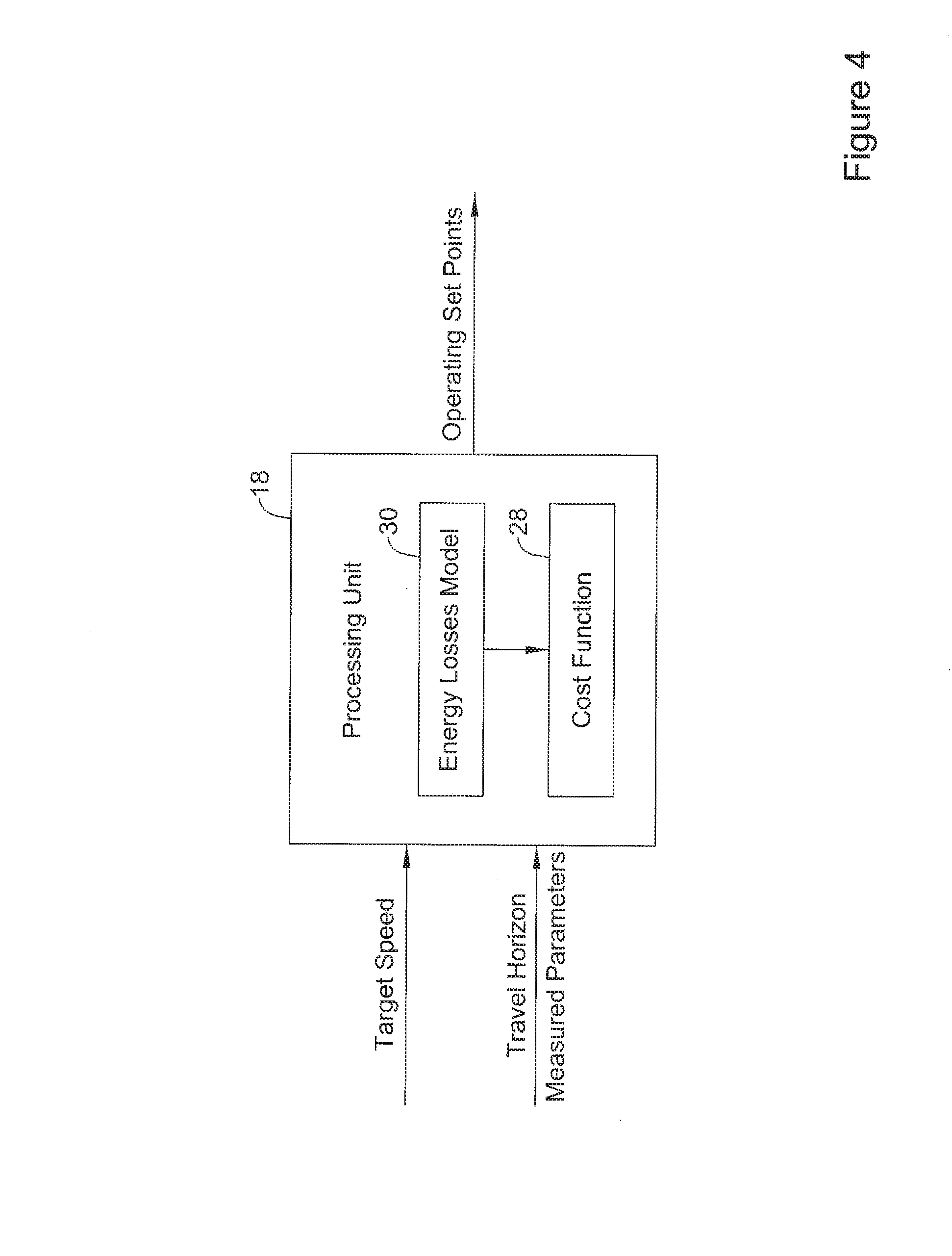
[0029] Turning to FIG. 4, the processing unit 18 is depicted with illustrative inputs and outputs, where the outputs may be based at least in part on the inputs. In some cases, the output of the processing unit may include operating set points for the propulsion device 14 based, at least in part, on received one or more measures of the parameters related to a travel horizon.
[0030] The processing unit 18 may include a vehicle operating model and a cost function 28. In one example, the vehicle operating model may be or may include a model of energy balances of the vehicle 10, such as an energy losses model 30 for the vehicle 10. The processing unit 18 of the controller 16 may optimize a cost function over a travel horizon, where the cost function is based at least in part on estimated energy losses according to the energy losses model 30 to set an actual speed for the vehicle.
[0031] The energy losses model 30 may estimate the energy losses over a travel horizon for a vehicle 10. In some cases, the energy losses model 30 may take into account losses of power and/or recoverable power. Example losses of power may include power loss due to aerodynamic drag for the vehicle 10, power loss due to friction of tires and powertrain (e.g., which may include engine friction), power loss due to conversion of primary energy into mechanical energy in the propulsion device (e.g. thermal losses of a combustion engine), and/or other power losses. Recoverable power may include power related to the grade-force and acceleration power.
[0032] Power losses due to aerodynamic drag and a quadratic term of friction may be represented by:
P.sub.l,1=(.theta..sub.1v.sup.2)v (1)
where, .theta..sub.1 is a constant proportional to a combination of a drag coefficient and a quadratic term of friction, and v is a velocity of the vehicle 10.
[0033] Power losses due to friction of tires on the vehicle 10 and a powertrain of the vehicle 10 may be represented by:
P.sub.l,2=(.theta..sub.2v+.theta..sub.3)v (2)
where, .theta..sub.2 is a constant proportional to a linear term of friction, .theta..sub.3 is a constant proportional to a friction force and v is a velocity of the vehicle 10.
[0034] As mentioned above, the losses model 30 may take into account recoverable power of the vehicle 10, including but not limited to power related to the grade-force acting on vehicle 10 and acceleration power. Power related to the grade-force acting on a vehicle may be represented by:
P.sub.g=mgsin(.phi.)v (3)
where, m is the mass of the vehicle and its contents, g is a gravitational acceleration constant (e.g., 9.81 meters per second squared), .phi. is a grade angle of the route on which the vehicle is traveling, and v is the velocity of the vehicle 10. Power related to the grade-force acting on a vehicle may be accumulated as potential energy of the vehicle 10. The grade angle may be road grades of roads on which the vehicle 10 is to travel over the travel horizon and/or a current road grade of a road on which the vehicle 10 may be positioned. Further, the grade angle may be determined by sensors in the vehicle 10, a GPS in communication with the controller 16 of the vehicle 10, a maps program saved in the memory 20 of the controller 16, a remote maps program in communication with the controller 16, and/or in one or more other manners.
[0035] Acceleration power may be represented by:
P.sub.a=mav (4)
where, m is the mass of the vehicle 10 and its contents, a is the acceleration of the vehicle 10, and v is the velocity of the vehicle 10. Acceleration power may be accumulated as kinetic energy of the vehicle 10.
[0036] Acceleration of the vehicle may be represented by:
a = 1 m ( f ( u e ) - ( .theta. 1 v 2 + .theta. 2 v + .theta. 3 + m g sin ( .PHI. ) ) ) ( 5 ) ##EQU00001##
where, f(u.sub.e) is an algebraic function for the vehicle propulsion force depending on variable u.sub.e, u.sub.e is a variable that could be one or more parameters of the propulsion device including brake torque, T.sub.brake, m is the mass of the vehicle 10 and its contents, .theta..sub.1 is a constant proportional to a combination of a drag coefficient and a quadratic term of friction, .theta..sub.2 is a constant proportional to a linear term of friction, .theta..sub.3 is a constant proportional to a friction force, g is a gravitational acceleration constant, .phi. is a grade angle of the route on which the vehicle is traveling, and v is the velocity of the vehicle 10.
[0037] Velocity of the vehicle may be represented by:
v=v.sub.0+.intg.a dt (6)
where, v.sub.0 is an initial velocity of the vehicle 10, a is the acceleration of the vehicle 10.
[0038] Power losses due to conversion efficiency of the propulsion device may be represented by:
P l , e = 1 - .eta. e ( n e , u e ) .eta. e ( n e , u e ) ( P l , 1 + P l , 2 + P g + P a ) ( 7 ) ##EQU00002##
where, .eta..sub.e(.eta..sub.e, u.sub.e) is a conversion efficiency of the propulsion device 14 (e.g. the thermal efficiency of a combustion engine) of the vehicle 10 and may typically be a value between zero and one, n.sub.e is propulsion device speed, u.sub.e is a variable that could be one or more parameters of the propulsion device including brake torque, T.sub.brake, and P.sub.l,1, P.sub.l,1, P.sub.g, P.sub.a are power terms according to equations (1) to (4) above. In some cases, to determine power losses due to conversion efficiency of the propulsion device, only the difference between a physically maximum possible efficiency (e.g. the Carnot efficiency of a combustion engine) and an effective conversion efficiency may be considered.
[0039] Generally, distance-specific total primary-energy (e.g. fuel energy or electrical energy) over a travel horizon may be modeled by:
E tot = 1 v mean T .intg. 0 T 1 .eta. e ( n e , u e ) ( P l , 1 + P l , 2 + P g + P a ) dt ( 8 ) ##EQU00003##
where, v.sub.mean is an average velocity of the vehicle over the travel horizon, T is a travel horizon of the vehicle 10, .eta..sub.e(n.sub.e, u.sub.e) is a conversion efficiency of the propulsion device 14 (e.g. a thermal efficiency of a combustion engine) of the vehicle 10, n.sub.e is propulsion device speed, u.sub.e is a variable that could be one or more parameters of the propulsion device including brake torque, T.sub.brake.
[0040] The distance-specific total primary-energy (e.g. fuel energy) model of equation (8) has typically been used to model the energy consumed by a vehicle 10 over a travel horizon. However, herein a different proposed model may utilize distance specific total losses of energy of the vehicle 10 based on the energy losses referred to above and may be represented by:
E loss = 1 v mean T .intg. 0 T ( 1 - .eta. e ( n e , u e ) .eta. e ( n e , u e ) ( P l , 1 + P l , 2 + P g P a ) + P l , 1 + P l , 2 ) dt ( 9 ) ##EQU00004##
where, v.sub.mean is an average velocity of the vehicle over the travel horizon, T is a travel horizon of the vehicle 10, the first summand in the integral represents power losses due to conversion efficiency of the propulsion device (see equation (7)), and P.sub.l,1 and P.sub.l,2 represent drag and friction losses of the vehicle according to equations (1) and (2), respectively.
[0041] The energy losses model may then be used in a cost function 28 to determine an optimum speed of the vehicle 10 over a travel horizon, which may be represented as follows as a sum over N.sub.horz incremental parts of the travel horizon:
J = i = 1 N horz c E ( E i E n ) 2 + c v ( v i - v ref v n ) 2 ( 10 ) ##EQU00005##
where, c.sub.E and c.sub.v are weights that typically may sum to one and are determined based on experimentation and/or user preferences, E.sub.i is the energy model of the vehicle over increment i of the travel horizon (e.g., either the energy losses model 30 using equation (9) or the energy losses model 30 using the distance-specific primary-energy model according to equation (8)), E.sub.n is an energy normalization factor that may be a function of target speed of the vehicle 10, v.sub.i is an average speed of the vehicle 10 over increment i of the travel horizon, v.sub.ref is a target speed of the vehicle, and v.sub.n is a speed normalization factor of the vehicle. The cost function 28 shown in equation (10) may be extended or expanded to include other terms based on user preferences. Such user preferences may include a desired maximum change in acceleration, a desired maximum acceleration, a desired time to travel a travel horizon, and/or one or more other desired factors.
[0042] Thus, based on using an energy losses model for a vehicle 10 traveling over a travel horizon one can obtain a more precise understanding of energy consumed by the vehicle 10 over the travel horizon. From this, the controller 16 of the vehicle 10 may be able to more precisely calculate an optimized speed for the vehicle to travel based on a target speed for the vehicle 10.
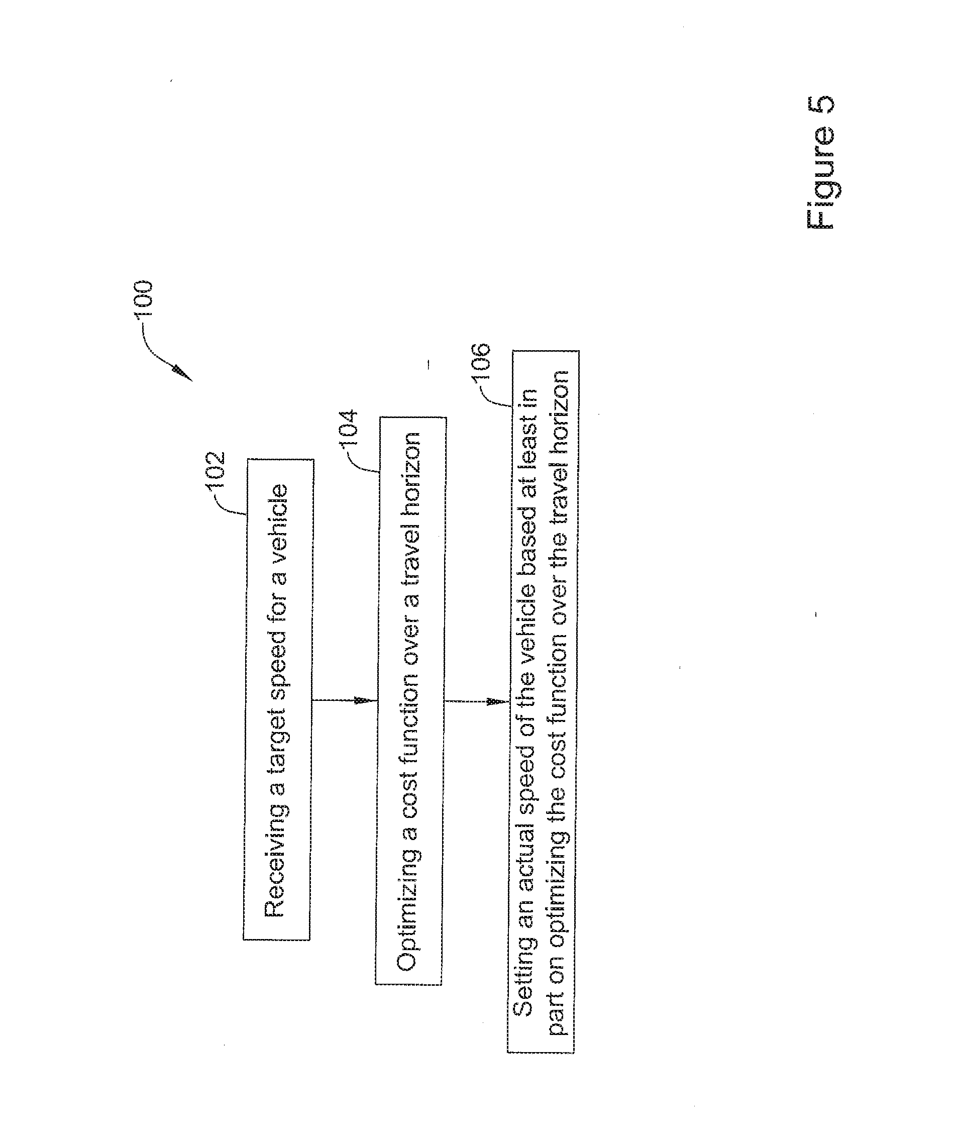
[0043] The optimization technique for a vehicle utilizing an energy losses model 30 of the vehicle 10 may be used in one or more approaches or methods, including a cruise control system approach. FIG. 5 depicts one example of using the above described energy losses model 30 in a process 100 for establishing an actual speed of a vehicle 10 from a user-specified target speed. The process 100 may include at step 102 receiving a target speed for a vehicle. In some cases, the target speed for the vehicle 10 may be received at the controller 16 in communication with the propulsion device 14 that may power the vehicle 10. At step 104, the process 100 may include optimizing a cost function 30 over a travel horizon of the vehicle 10. In some cases, the cost function 28 may be optimized over the travel horizon of the vehicle 10 based, at least in part, on energy losses of the vehicle over the travel horizon relative to the received target speed. For example, the controller 16 may use the cost function 28 utilizing a model as in equation (9) to determine and minimize the energy losses of the vehicle 10 over the travel horizon to determine an optimal speed of the vehicle 10 in view of the target speed. At step 106, an actual speed of the vehicle 10 may be set based, at least in part, on optimizing the cost function over the travel horizon.
[0044] The controller 16 of the vehicle 10 may optimize the cost function over the travel horizon. However, in some cases, one or more other controllers may optimize the cost function over the travel horizon and input the results of optimization to the controller 16 for determining propulsion-device set points (e.g. engine brake torque).
[0045] In some cases, the actual speed set may be the optimal speed of the vehicle identified by the cost function 28. Alternatively or in addition, the optimal speed may be presented to a user (e.g., driver) of the vehicle and the user may be given an option of setting the speed of the vehicle at the determined optimal speed or some other speed based on knowing the optimal speed for the user's requirements and the energy losses of the vehicle.
[0046] In some cases, the approach 100 may be used in a cruise control module 19 of the controller 16. The cruise control module 19 may control the propulsion device to establish a speed of the vehicle 10. In the cruise control module 19, the target speed may be a user specified cruise control speed and the set actual speed may be the established speed of the vehicle.
[0047] FIG. 6 is a diagram of energy flows that correspond to the powers in equations. The power distribution "part" may balance the energy flows (powers) depending on physics and parameters such as vehicle mass, road grade, vehicle speed, such that the sum of all energy flows connected to the power distribution "part" is zero. Symbol 41 may resemble a primary energy reservoir (e.g., fuel reservoir or battery) having a primary-energy flow 42 to a propulsion device 43 (e.g., combustion engine). Energy conversion losses 44 may flow from device 43. An energy flow 45 propelling a vehicle may go to a symbol 46 indicating parameter dependent distribution (balancing) of energy flows (e.g., parameters of speed, road grade, vehicle mass, so forth. From symbol 46 is shown a flow 49 of drag and friction losses. There may be a two way flow 47 between symbol 46 and a vehicle kinetic energy block 51. Also, there may be a two way flow 48 between symbol 46 and a vehicle potential energy block 52.
[0048] The following is a recap of the above disclosure. A vehicle system may include a vehicle, a propulsion device such as a combustion engine, and a controller. The propulsion device may be configured to at least partially power the vehicle and the controller may be in communication with the propulsion device for controlling the propulsion device according to a target speed of the vehicle. The controller may include a model of energy balances of the vehicle and may be configured to use the model to estimate energy losses over a travel horizon of the vehicle. The controller may be configured to optimize in each processing step a cost function over the travel horizon of the vehicle based at least in part on the estimated energy losses to set an actual speed for the vehicle.
[0049] Further, the controller of the vehicle system may be configured to optimize the cost function at least in part by minimizing the energy losses relative to the target speed.
[0050] Further, the controller of the vehicle system may include a cruise control module and the target speed is a user specified cruise control speed.
[0051] The actual speed of the vehicle system as set by the controller may be the actual speed of the vehicle after a user has specified the user specified cruise control speed.
[0052] The travel horizon of the vehicle of the vehicle system may be a time interval.
[0053] The model of energy balances of the vehicle may include a parameter of road grades of roads on which the vehicle may travel over the travel horizon.
[0054] The model of energy balances of the vehicle system may include a parameter of a current road grade on which the vehicle is positioned.
[0055] The model of energy balances of the vehicle of the vehicle system may include a mass of the vehicle as a parameter.
[0056] The estimated energy losses of the vehicle system over the travel horizon may include energy loss due to aerodynamic drag of the vehicle.
[0057] The estimated energy losses of the vehicle system over the travel horizon may include energy loss due to friction.
[0058] The estimated energy losses of the vehicle over the travel horizon may include energy loss due to energy-conversion loss propulsion device (e.g., thermal loss from the engine) of the vehicle.
[0059] An approach for establishing an actual speed of a vehicle from a user-specified target speed may include receiving a target speed for a vehicle. The target speed is received at a controller in communication with a propulsion device configured to at least partially power the vehicle, optimizing a cost function over a travel horizon based at least in part on energy losses of the vehicle over the travel horizon relative to the target speed, and setting an actual speed of the vehicle based at least in part on optimizing the cost function over the travel horizon.
[0060] Further, the controller in the approach may include a model of vehicle energy balances to calculate the energy losses of the vehicle over the travel horizon.
[0061] Further, the approach may include optimizing a cost function over a travel horizon based at least in part on energy losses of the vehicle over a travel horizon based, at least in part, on minimizing energy losses of the vehicle over the travel horizon relative to target speed to establish an optimal speed.
[0062] The approach may further include obtaining one or more measures of parameters related to the travel horizon, wherein optimizing the cost function may take into account the obtained one or more measures of parameters related to the travel horizon.
[0063] Further, the controller in the approach may include a cruise control module configured to control the propulsion device to establish a speed of the vehicle and the target speed may be a user specified cruise control speed and the set actual speed may be the established speed of the vehicle.
[0064] A controller may be provided for a vehicle powered by a propulsion device. The controller may include a processing unit, an input for receiving one or more measures of parameters at the processing unit, and an output for providing one or more operating set points to the propulsion device based at least in part on the received one or more measures of parameters. The processing unit may receive a target speed for the vehicle over a travel horizon, may obtain one or more measures of parameters related to a travel horizon, and may optimize a cost function of the vehicle to provide operating set points for the propulsion device by minimizing energy losses of the vehicle relative to the received target speed and one or more obtained measures of parameters related to the travel horizon.
[0065] The provided operating conditions determined by the controller may establish an actual speed of the vehicle.
[0066] The energy losses minimized may include one or more of energy loss due to aerodynamic drag, friction present in the propulsion device, the powertrain, and in the tires, and a conversion loss from the propulsion device (e.g., thermal loss from the combustion engine).
[0067] The obtained measures of parameters related to a travel horizon may include one or more of a mass of the vehicle and a road grade of a road on which the vehicle is positioned over a travel horizon.
[0068] In the present specification, some of the matter may be of a hypothetical or prophetic nature although stated in another manner or tense.
[0069] Although the present system and/or approach has been described with respect to at least one illustrative example, many variations and modifications will become apparent to those skilled in the art upon reading the specification. It is therefore the intention that the appended claims be interpreted as broadly as possible in view of the related art to include all such variations and modifications.
* * * * *
D00000
D00001
D00002
D00003
D00004
D00005
D00006
XML
uspto.report is an independent third-party trademark research tool that is not affiliated, endorsed, or sponsored by the United States Patent and Trademark Office (USPTO) or any other governmental organization. The information provided by uspto.report is based on publicly available data at the time of writing and is intended for informational purposes only.
While we strive to provide accurate and up-to-date information, we do not guarantee the accuracy, completeness, reliability, or suitability of the information displayed on this site. The use of this site is at your own risk. Any reliance you place on such information is therefore strictly at your own risk.
All official trademark data, including owner information, should be verified by visiting the official USPTO website at www.uspto.gov. This site is not intended to replace professional legal advice and should not be used as a substitute for consulting with a legal professional who is knowledgeable about trademark law.