Processing Planar Workpieces
Wilhelm; Markus ; et al.
U.S. patent application number 16/360657 was filed with the patent office on 2019-07-18 for processing planar workpieces. The applicant listed for this patent is TRUMPF Werkzeugmaschinen GmbH + Co. KG. Invention is credited to Dominik Bitto, Rainer Hank, Christian Jakisch, Jens Kappes, Marc Klinkhammer, Markus Maatz, Joerg Neupert, Simon Ockenfuss, Leonard Schindewolf, Alexander Tatarczyk, Dennis Traenklein, Markus Wilhelm.
| Application Number | 20190217368 16/360657 |
| Document ID | / |
| Family ID | 60083927 |
| Filed Date | 2019-07-18 |


View All Diagrams
| United States Patent Application | 20190217368 |
| Kind Code | A1 |
| Wilhelm; Markus ; et al. | July 18, 2019 |
PROCESSING PLANAR WORKPIECES
Abstract
Methods, devices and systems for machining plate-like workpieces, in particular metal sheets, are provided. In one aspect, a plate workpiece processing device has an upper tool and a lower tool. The upper tool and the lower tool can be moved toward each other to machine a workpiece arranged between. The upper tool has a clamping shaft and a base body, which include a common position axis. The upper tool also includes a machining tool arranged on the base body, opposite the clamping shaft. The lower tool has a base body which includes a supporting surface for the workpiece and an opening located within the supporting surface. A tool body accommodating the machining tool has a longitudinal axis which is inclined with respect to the positioning axis of the upper tool.
| Inventors: | Wilhelm; Markus; (Gerlingen, DE) ; Bitto; Dominik; (Muenchingen, DE) ; Hank; Rainer; (Eberdingen/Hochdorf, DE) ; Klinkhammer; Marc; (Ditzingen, DE) ; Schindewolf; Leonard; (Rutesheim, DE) ; Ockenfuss; Simon; (Boeblingen, DE) ; Kappes; Jens; (Leinfelden-Echterdingen, DE) ; Traenklein; Dennis; (Nufringen, DE) ; Tatarczyk; Alexander; (Hoeffingen, DE) ; Neupert; Joerg; (Stuttgart, DE) ; Maatz; Markus; (Leinfelden-Echterdingen, DE) ; Jakisch; Christian; (Boeblingen, DE) | ||||||||||
| Applicant: |
|
||||||||||
|---|---|---|---|---|---|---|---|---|---|---|---|
| Family ID: | 60083927 | ||||||||||
| Appl. No.: | 16/360657 | ||||||||||
| Filed: | March 21, 2019 |
Related U.S. Patent Documents
| Application Number | Filing Date | Patent Number | ||
|---|---|---|---|---|
| PCT/EP2017/074299 | Sep 26, 2017 | |||
| 16360657 | ||||
| Current U.S. Class: | 1/1 |
| Current CPC Class: | B21D 28/34 20130101; B21D 28/02 20130101; B21D 28/125 20130101; B21D 19/08 20130101; B21D 35/001 20130101 |
| International Class: | B21D 28/34 20060101 B21D028/34; B21D 19/08 20060101 B21D019/08; B21D 28/12 20060101 B21D028/12; B21D 35/00 20060101 B21D035/00 |
Foreign Application Data
| Date | Code | Application Number |
|---|---|---|
| Sep 26, 2016 | DE | 102016118175.7 |
| Oct 12, 2016 | DE | 102016119435.2 |
Claims
1. A planar workpiece processing device, comprising: an upper tool comprising: a clamping shaft; an upper main body, wherein the clamping shaft and the upper main body have a joint positioning axis; and a processing tool arranged opposite to the clamping shaft on the upper main body; and a lower tool comprising: a lower main body; and a rest surface and an opening disposed within the rest surface, wherein the upper tool and the lower tool are moveable towards one another to process a workpiece arranged therebetween, and wherein the processing tool acting on the workpiece comprises a tool body receiving the processing tool and having a longitudinal axis inclined relative to the positioning axis of the upper tool.
2. The planar workpiece processing device of claim 1, wherein the processing tool is inclined relative to the positioning axis in an angular range from 0.degree. to 90.degree..
3. The planar workpiece processing device of claim 1, wherein the processing tool is formed as a cutting tool and at least one cutting edge is provided at a free end of the tool body.
4. The planar workpiece processing device of claim 3, wherein the at least one cutting edge has a punch surface oriented at right angles to the longitudinal axis of the tool body, and wherein a counter cutting edge positioned in the opening is provided on the lower tool.
5. The planar workpiece processing device of claim 4, wherein the counter cutting edge is arranged in the rest surface of the lower main body of the lower tool or elevated in a direction of the upper tool relative to the rest surface.
6. The planar workpiece processing device of claim 4, wherein a cutting surface is provided adjacently to the counter cutting edge and is oriented at an incline or parallel to the longitudinal axis of the tool body.
7. The planar workpiece processing device of claim 6, wherein a counter die is provided at a distance from the cutting surface.
8. The planar workpiece processing device of claim 4, wherein a support surface adjacent to the counter cutting edge is inclined relative to the rest surface on the lower main body of the lower tool and protrudes relative thereto in a direction of the upper tool.
9. The planar workpiece processing device of claim 8, wherein the support face is adapted in respect of its angle to a bent portion on the workpiece to be processed,
10. The planar workpiece processing device of claim 1, wherein the processing tool is formed as at least one of a signing tool, an engraving tool, an embossing tool with an embossing element, a bending tool, and a shaping tool.
11. The planar workpiece processing device of claim 1, wherein the tool body is formed as one of a bending tool having at least one bending edge and a shaping tool having a punch surface and a shaping element arranged thereon.
12. A planar workpiece processing machine, comprising: an upper tool comprising: a clamping shaft; an upper main body, wherein the clamping shaft and the upper main body have a joint positioning axis; and a processing tool arranged opposite to the clamping shaft on the upper main body, wherein the upper tool is moveable with an upper stroke movement along an upper stroke axis by an upper stroke drive device in a first direction of a workpiece to be processed by the upper tool and in a second, opposite direction, and is positionable along the joint positioning axis running perpendicular to the upper stroke axis and displaceable with an upper traversing movement by an upper drive assembly along the joint positioning axis; a lower tool comprising: a lower main body; and a rest surface and an opening disposed within the rest surface, wherein the lower tool is oriented relative to the upper tool, and the lower tool is movable with a lower stroke movement along a lower stroke axis by a lower stroke drive device in a direction of the upper tool and positionable along a lower positioning axis and moveable with a lower traversing movement by a lower drive assembly along the lower positioning axis; and a controller configured to control the upper and lower drive assemblies to move the upper tool and the lower tool, respectively, wherein the upper traversing movement of the upper tool along the joint positioning axis and the lower traversing movement of the lower tool along the lower positioning axis are controllable independently of one another, wherein the upper tool and the lower tool are moveable towards one another to process the workpiece arranged therebetween, wherein the processing tool acting on the workpiece comprises a tool body receiving the processing tool and having a longitudinal axis inclined relative to the joint positioning axis of the upper tool, and wherein at least one of the upper tool and the lower tool is controllable with a corresponding stroke movement lying outside a corresponding stroke axis.
13. A method of processing planar workpieces, comprising: positioning a workpiece to be processed between an upper tool and a lower tool of a planar workpiece processing device; moving the upper tool along a stroke axis with an upper stroke movement by a stroke drive device in at least one of a first direction of the workpiece to be processed and a second, opposite direction; displacing the upper tool with an upper traversing movement by a first drive assembly along an upper positioning axis running perpendicular to the stroke axis; displacing the lower tool oriented relative to the upper tool with a lower traversing movement by a second motor drive assembly along a lower positioning axis oriented perpendicular to the stroke axis; and processing the workpiece by the planar workpiece processing device, wherein the first and second drive assemblies are actuated by a controller to move the upper tool and the lower tool, respectively, wherein the upper tool comprises a clamping shaft, an upper main body, and a processing tool arranged opposite to the clamping shaft on the upper main body, wherein the clamping shaft and the upper main body have the upper positioning axis as a joint positioning axis, and wherein the processing tool acting on the workpiece comprises a tool body receiving the processing tool and having a longitudinal axis inclined relative to the upper positioning axis of the upper tool, wherein the lower tool comprises a lower main body and a rest surface for the workpiece and an opening disposed within the rest surface, wherein the upper tool and the lower tool are moveable towards one another to process the workpiece arranged therebetween, and wherein at least one of the upper tool and the lower tool is controllable with a corresponding stroke movement lying outside a corresponding stroke axis.
14. The method of claim 13, comprising: controlling the upper tool to move with a linear stroke movement inclined relative to the stroke axis or a curved or arcuate stroke movement relative to the stroke axis.
15. The method of claim 13, comprising: displacing the upper tool by a particular stroke movement along the stroke axis towards the lower tool and then along the upper positioning axis relative to the lower tool that is positioned stationary.
16. The method of claim 13, comprising orienting a cutting gap in the workpiece by at least one of adjusting at least one of the upper tool and the lower tool by a rotary movement about a corresponding positioning axis to orient the upper tool and the lower tool relative to one another, displacing at least one of the upper tool and the lower tool along the corresponding positioning axis, and controlling at least one of the upper tool and the lower tool with a superposition of the rotary movement about the corresponding positioning axis and a corresponding traversing movement along the corresponding positioning axis.
17. The method of claim 13, comprising adjusting a cutting gap width between a cutting edge of the upper tool and at least one of an inner counter cutting edge of the lower tool and an outer counter cutting edge of the lower tool by at least one of adjusting at least one of the upper tool and the lower tool by a rotary movement about a corresponding positioning axis to orient the upper tool and the lower tool relative to one another, displacing at least one of the upper tool and the lower tool along the corresponding positioning axis, and controlling at least one of the upper tool and the lower tool with a superposition of the rotary movement about the corresponding positioning axis and a corresponding traversing movement along the corresponding positioning axis.
18. The method of claim 13, wherein the upper tool and the lower tool are formed as a punch and a die, respectively.
19. The method of claim 13, comprising: producing a bent portion on the workpiece by displacing the upper tool towards the lower tool by a particular stroke movement along the stroke axis; and shaping the bent portion with a pivoting and bending movement by displacing the upper tool with a subsequent traversing movement along the upper positioning axis relative to the lower tool.
Description
CROSS REFERENCE TO RELATED APPLICATIONS
[0001] This application is a continuation of and claims priority under 35 U.S.C. .sctn. 120 from PCT Application No. PCT/EP2017/074299 filed on Sep. 26, 2017, which claims priority from German Application No. 10 2016 118 175.7, filed on Sep. 26, 2016, and German Application No. 10 2016 119 435.2, filed on Oct. 12, 2016. The entire contents of each of these priority applications are incorporated herein by reference.
TECHNICAL FIELD
[0002] The invention relates to a tool and a machine tool and a method for processing planar workpieces, preferably metal sheets.
BACKGROUND
[0003] A machine tool of this kind is known from EP 2 527 058 B 1. That document discloses a machine tool in the form of a press for processing workpieces, wherein an upper tool is provided on a stroke device, which is moveable, relative to a workpiece to be processed, along a stroke axis in the direction of the workpiece and in the opposite direction. A lower tool is provided in the stroke axis and opposite the upper tool and is positioned towards a lower side. A stroke drive device for a stroke movement of the upper tool is controlled by a wedge gear. The stroke drive device with the upper tool arranged thereon is moveable along a positioning axis. The lower tool is moved synchronously relative to the upper tool by means of a motor drive.
[0004] Document DE 10 2006 049 044 A1 discloses a tool for processing planar workpieces which for example is useable in a machine tool according to EP 2 527 058 B1. This tool for cutting and/or shaping planar workpieces comprises a punch and a die. In order to process a workpiece arranged between the punch and the die, these are moved towards one another in a stroke direction. A cutting tool with a cutting edge is arranged on the punch, and at least two counter cutting edges are provided on the die. The punch and the die are rotatable relative to one another about a common positioning axis. The counter cutting edges are oriented here relative to the common positioning axis in such a way that the cutting edge of the cutting tool can be positioned relative to the counter cutting edges by means of a rotary movement of the cutting tool of the punch. The counter cutting edges are arranged at a distance from the positioning axis corresponding to the distance of the cutting edge from the common positioning axis.
[0005] Document EP 2 177 289 B1 also discloses a tool for cutting and/or shaping planar workpieces. This tool comprises a punch and a die that are again oriented relative to one another in a common positioning axis. The punch is mounted rotatably about this positioning axis so that at least one cutting edge of a cutting tool on the punch can be oriented relative to the at least one counter cutting edge on the die. The die comprises an opening in a rest surface for a workpiece, through which opening separated workpiece parts can be discharged. Adjacently to the opening there is provided a further counter cutting edge, which is arranged at the same distance from the positioning axis as the further counter cutting edge in the opening. A discharge surface of the metal sheet is provided on the counter cutting edge of the die disposed outside the opening. In this tool as well the distance of the counter cutting edges to the positioning axis corresponds to the distance of the cutting edge on the cutting tool of the punch from the positioning axis.
[0006] Document WO 02/043 892 A2 discloses a tool for cutting planar workpieces having an upper and a lower tool. The upper tool comprises a clamping shaft and a main body, which lie in a common positioning axis. A processing tool is provided on the main body and is opposite the clamping shaft. The lower tool comprises a main body with a rest surface for the workpiece and an opening within the rest surface. A cutting edge of the processing tool is oriented at an incline relative to a plane of the workpiece in order to form slots.
SUMMARY
[0007] One of the objects of the invention is to propose a tool and a machine tool and a method for cutting and/or shaping planar workpieces by means of which the versatility of the processing of workpieces is increased.
[0008] One aspect of the invention features a tool for cutting and/or shaping planar workpieces, in particular metal sheets, having the features of claim 1.
[0009] The tool for processing planar workpieces has a processing tool acting on the workpiece, wherein a tool body receiving the processing tool has a longitudinal axis which is inclined relative to the tool rotation axis or the positioning axis of the upper tool. This processing tool is preferably provided on the upper tool. By controlling a stroke movement of the upper tool, which can be controlled by a superposition of a traversing movement in the Y direction and in the Z direction, a stroke movement that deviates from a vertical stroke movement, in particular that is slanted, can be performed. By means of a slanted stroke movement of this kind, it is made possible for slanted cuts to be formed in a workpiece or a workpiece edge. For example, this makes it possible to produce slanted part edges. It is also possible to prepare welding edges on workpieces. In addition, it is possible that, when forming bent portions which are raised relative to a workpiece plane, a processing, in particular a punching stroke, can be performed. A right-angled part edge or also a slanted part edge can be introduced at a bent portion of this kind. In addition, further processing operations, such as bending, engraving or shaping, can be made possible by a tool body inclined relative to the positioning axis.
[0010] The orientation for a cut face on the workpiece can be determined by the inclination of the longitudinal axis of the tool body. A stroke movement of the upper tool towards the lower tool can preferably also be controlled in such a way that said movement runs along the longitudinal axis of the tool body.
[0011] It is preferably provided that the longitudinal axis of the processing tool is inclined relative to the positioning axis at an angle of up to 90.degree.. For example, this makes it possible, when a workpiece is resting on a workpiece rest surface, that processing of the end face or end side of the workpiece is also made possible, said end face or end side possibly being oriented for example perpendicularly to a rest surface of the workpiece.
[0012] In accordance with a first embodiment of the processing tool it is provided that this is formed as a cutting tool and the free end of the tool body has at least one cutting edge. Various cut contours or processing operations can be performed by the contour of a cutting edge of this kind and correspondingly with a counter cutting edge on the die.
[0013] A punch surface is preferably provided on the tool body and is preferably oriented at right angles to the longitudinal axis of the tool body, wherein at least one cutting edge is provided on the punch surface. The entire punch surface may advantageously be delimited by a peripheral cutting edge. For example, by means of a tool body of this kind, which on a punch surface has an upper and lower cutting edge and lateral cutting edges, which connect the upper and lower cutting edge, both a lower and an upper chamfer can be formed on the workpiece in a simple way. Furthermore, it is preferably provided that a counter cutting edge of the die lies in the rest surface of the main body of the lower tool. If an upper tool with an inclined tool main body is moved towards the die, a slanted cutting edge can be produced on the workpiece resting on the die.
[0014] Alternatively, it can be provided that a support surface adjacent to the counter cutting edge is inclined relative to the support surface on the main body of the lower tool and preferably protrudes relative thereto in the direction of the upper tool. The inclination of the support surface corresponds advantageously to the inclination of the punch surface. In the event of a stroke movement oriented perpendicularly to the support surface, a right-angled part edge can be produced in the case of a bent workpiece part.
[0015] Furthermore, it is preferably provided that a cutting surface is provided adjacently to the counter cutting edge and is formed at an incline or parallel to the longitudinal axis of the tool main body. Here, the tool body can be supported during the stroke movement. The cutting surface is preferably inclined relative to the longitudinal axis of the tool body, such that the cutting surface is distanced from the tool body as the working stroke of the tool body increases.
[0016] A further embodiment of the tool provides that a counter die is provided, which is distanced from the cutting surface. Here, it is provided that the distance is adapted to the thickness or size of the tool body which is guided during the cutting surface and the counter die during a stroke movement. By means of a counter die of this kind, an undesirable lifting of the work piece from the rest surface of the die can be prevented.
[0017] The support surface of the die adjacent to the counter cutting edge is preferably adapted in respect of its angle to a bent portion on the workpiece to be processed. Thus, the previously formed angle of the bent portion can be maintained while the bent portion is being processed.
[0018] In accordance with an alternative embodiment of the workpiece it is provided that this is formed as a signing tool or engraving tool. By means of the inclined orientation of the signing or engraving tool, a marking can be made on a bent portion or an end side of the workpiece.
[0019] Furthermore, it is alternatively provided that the tool is a bending and/or shaping tool. Various contours can thus be formed in the workpiece.
[0020] A further alternative of the tool provides that this is formed as an embossing tool.
[0021] Another aspect of the invention features a machine tool for processing planar workpieces in which the traversing movement of the upper tool along the upper positioning access and the traversing movement of the lower tool along the lower positioning access can be controlled independently of one another and a tool body is provided for processing workpieces, in which tool body a processing tool is inclined relative to the positioning axis of the upper tool. A stroke movement of the upper tool and/or the lower tool that lies outside the Z axis and can be superposed by a movement along the Y axis can be controlled by the machine-tool. The versatility both in respect of the processing and the use of tools is thus increased.
[0022] A further aspect of the invention features methods for processing planar workpieces, in which a tool is used which has a processing tool oriented at an incline relative to the positioning axis of the tool and in which the upper tool and/or the lower tool is controlled with a stroke movement lying outside the stroke axis. The versatility of the processing of workpieces can thus be increased.
[0023] It is preferably provided that a stroke movement of the upper tool and/or of the lower tool which has an inclined linear stroke movement relative to a stroke axis is controlled. For example, this inclined linear stroke movement can be oriented along a longitudinal axis of the tool body on the processing tool. Alternatively, it can be provided that a curved or arcuate stroke movement relative to the stroke axis, in particular the Z axis, is controlled. By means of the corresponding parameters for moving the upper tool relative to the lower tool, not only can cuts or material-removing operations be performed, but also rounding operations or shaping operations producing rounded or curved contours.
[0024] A further embodiment for processing workpieces preferably provides that the upper tool is moved by a stroke movement along the stroke axis towards the lower tool and is then moved along an upper positioning access, wherein, during the stroke movement and the subsequent traversing movement along the positioning axis, the lower tool is positioned in a stationary manner. For example, a pivoting and bending processing operation can be carried out on a tab that has been cut free in the workpiece. Thus, a bent portion can also be produced. The pivot angle of the bent portion can be adjusted depending on the path of movement along the stroke access and along the positioning axis. If, for example, a bent portion through 90.degree. has been produced by a stroke movement of the upper tool relative to the lower tool, a subsequent traversing movement along the upper positioning access can introduce a further pivoting movement of the bent portion, such that the tab or bent portion can be bent by more than 90.degree. relative to a workpiece plane.
[0025] It is furthermore preferably provided that the upper tool and/or lower tool are controlled by a rotary movement about the positioning axis thereof and/or by a traversing movement along the particular positioning axis in order to orient the upper and lower tool relative to a cutting gap in the tool or to adjust a cutting gap width between the cutting edge of the punch and a counter cutting edge of the die or to sever a remaining connection.
DESCRIPTION OF DRAWINGS
[0026] The invention and further advantageous embodiments and developments thereof will be described and explained in greater detail hereinafter with reference to the examples shown in the drawings. The features inferred from the description and the drawings can be applied in accordance with the invention individually or in any combination. In the drawings:
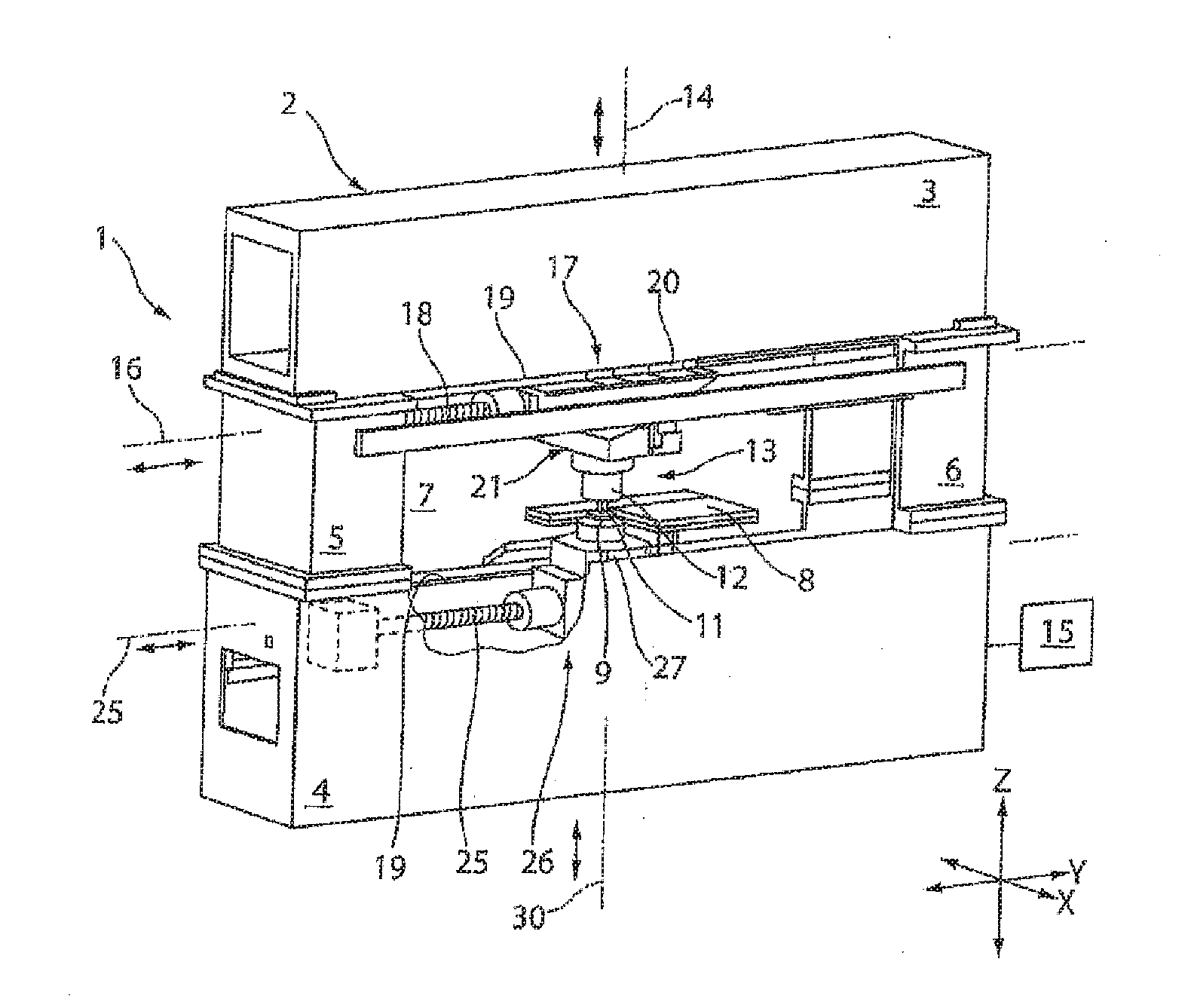
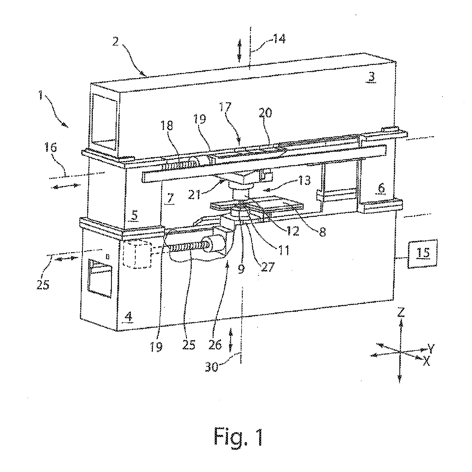
[0027] FIG. 1 shows a perspective view of the machine tool;
[0028] FIG. 2 shows a schematic depiction of the fundamental structure of a stroke drive device and a motor drive according to FIG. 1,
[0029] FIG. 3 shows a schematic graph of a superposed stroke movement in the Y and Z direction of the ram according to FIG. 1;
[0030] FIG. 4 shows a schematic graph of a further superposed stroke movement in the Y and Z direction of the ram according to FIG. 1;
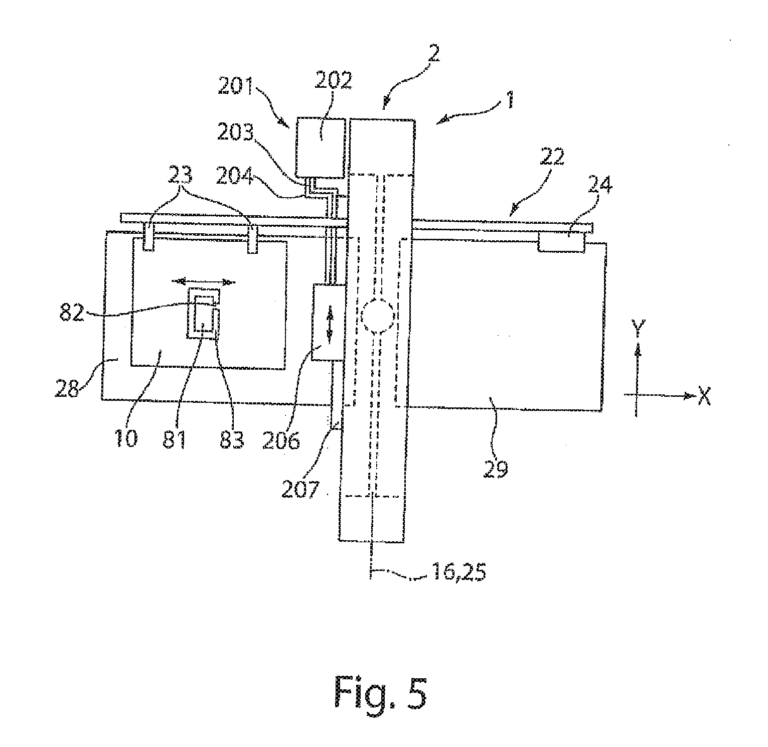
[0031] FIG. 5 shows a schematic view from above of the machine tool according to FIG. 1 with workpiece rest surfaces;
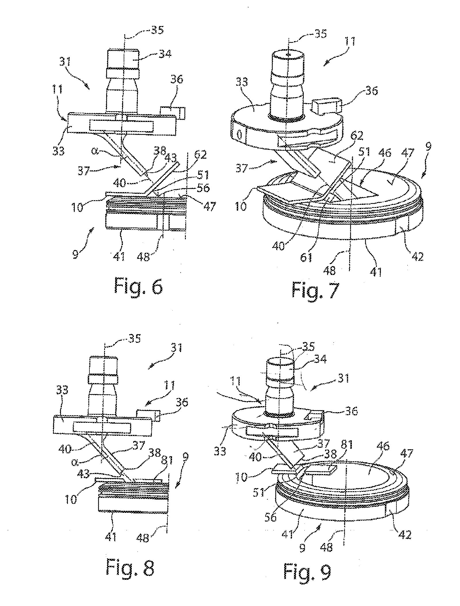
[0032] FIG. 6 shows a schematic side view of a first embodiment of a tool for a slanted punching stroke;
[0033] FIG. 7 shows a perspective view of the tool according to FIG. 6;
[0034] FIG. 8 shows a schematic side view of an alternative embodiment of the tool as compared to FIG. 6;
[0035] FIG. 9 shows a perspective view of the tool according to FIG. 8;
[0036] FIG. 10 shows a schematic side view of a further alternative embodiment of the tool as compared to FIG. 6;
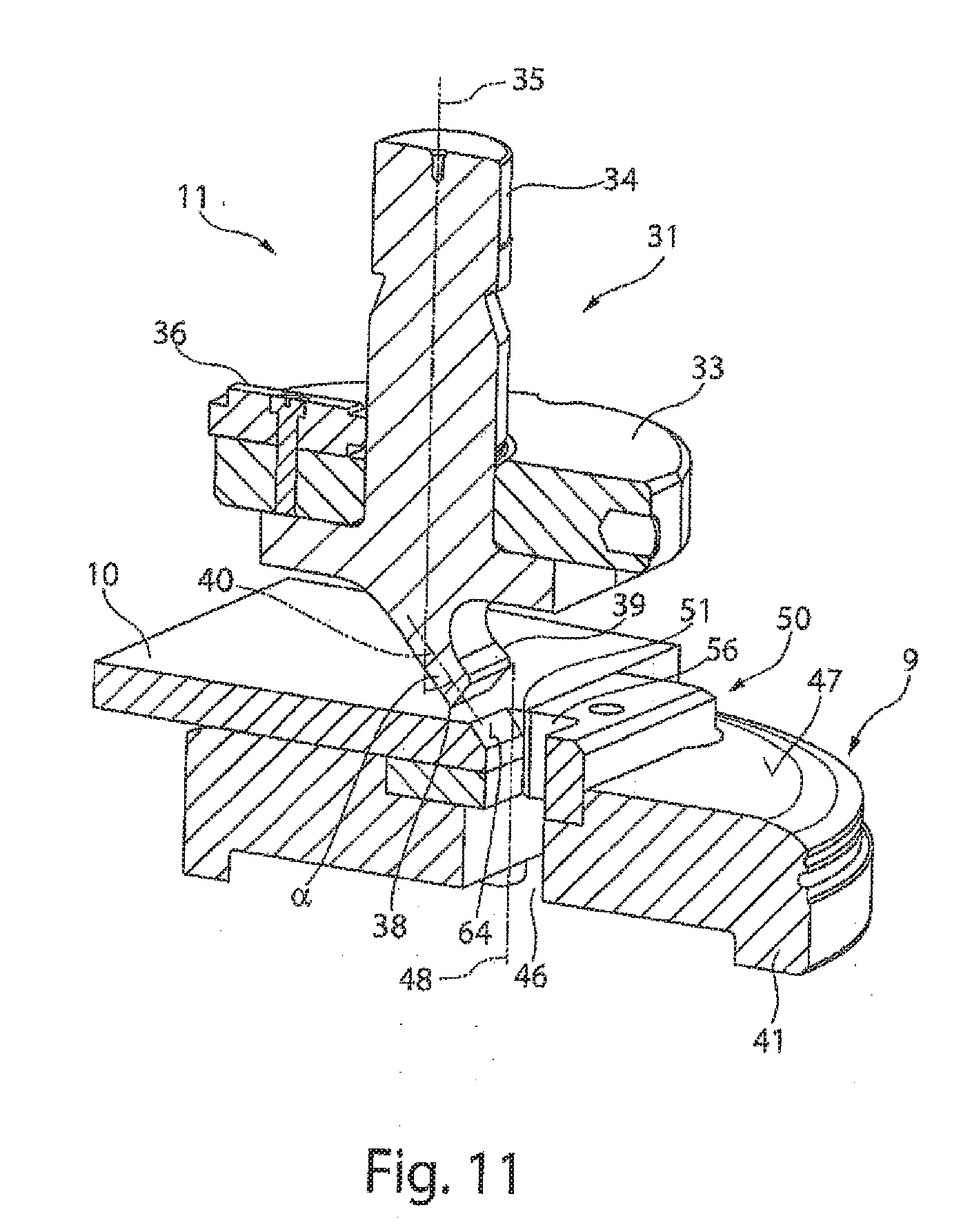
[0037] FIG. 11 shows a perspective view of the tool according to FIG. 10 in a working position;
[0038] FIG. 12 shows a perspective view of a further alternative embodiment of the tool as compared to FIG. 6;
[0039] FIG. 13 shows a further perspective view of the embodiment of the tool in FIG. 12;
[0040] FIG. 14 shows a schematic side view of a further alternative embodiment of a tool;
[0041] FIG. 15 shows a perspective view of an alternative embodiment of the tool as compared to FIG. 8;
[0042] FIG. 16 shows a perspective view of a tool for embossing the workpiece;
[0043] FIG. 17 shows a perspective view of a tool for shaping the workpiece;
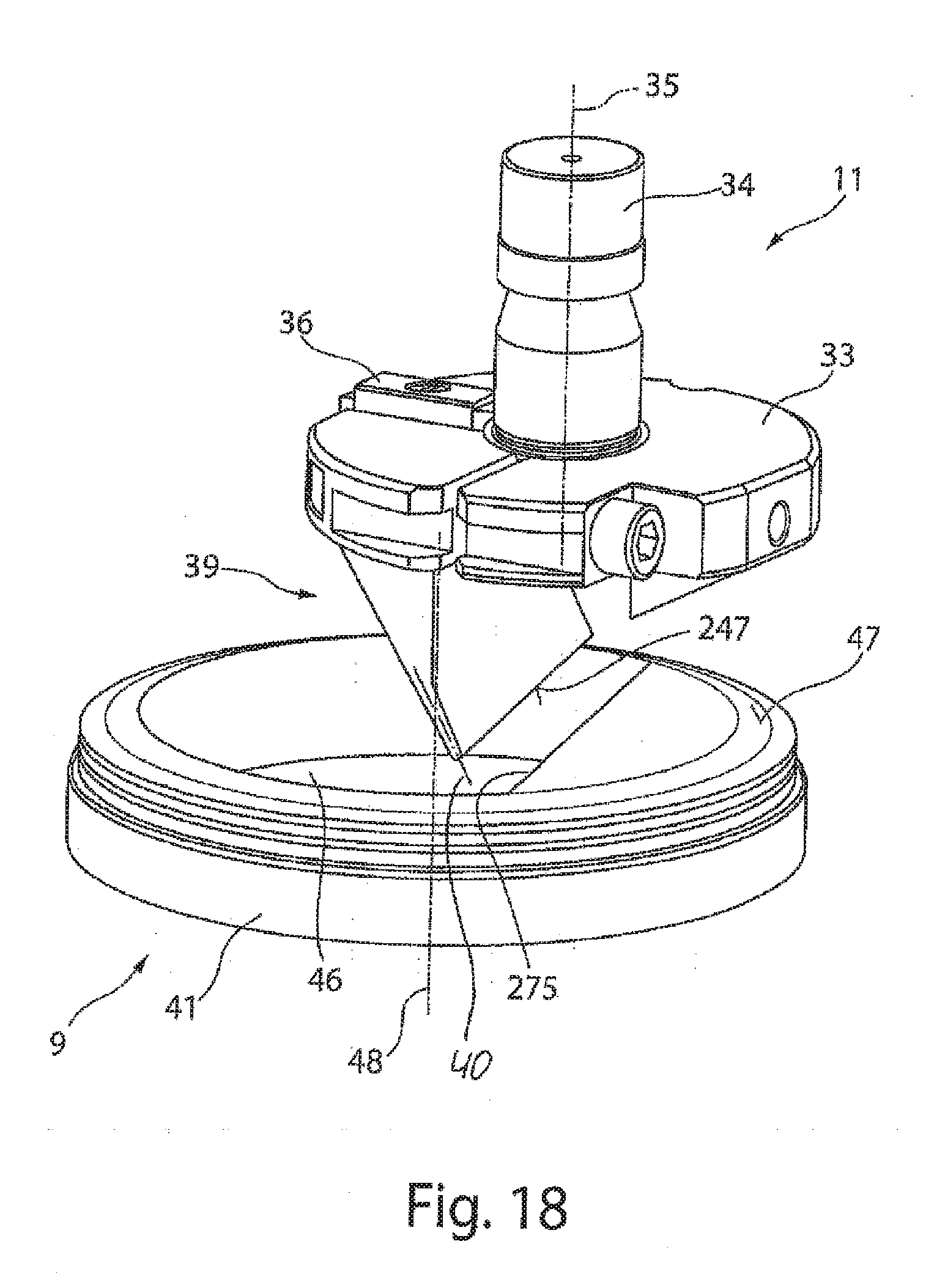
[0044] FIG. 18 shows a perspective view of the tool for pivoting and bending the workpiece;
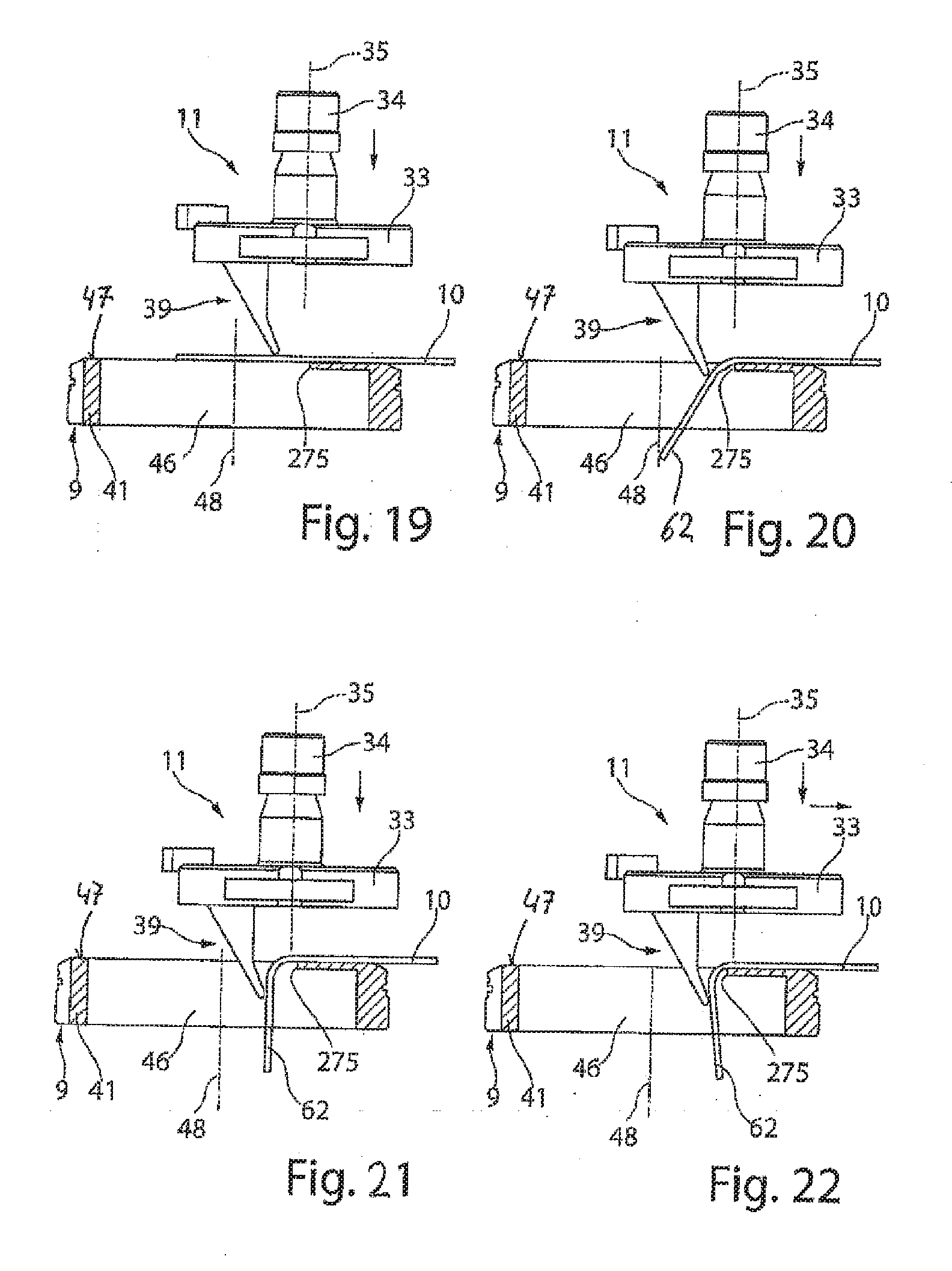
[0045] FIGS. 19-22 show schematic side views depicting a pivoting and bending processing operation on a workpiece; and
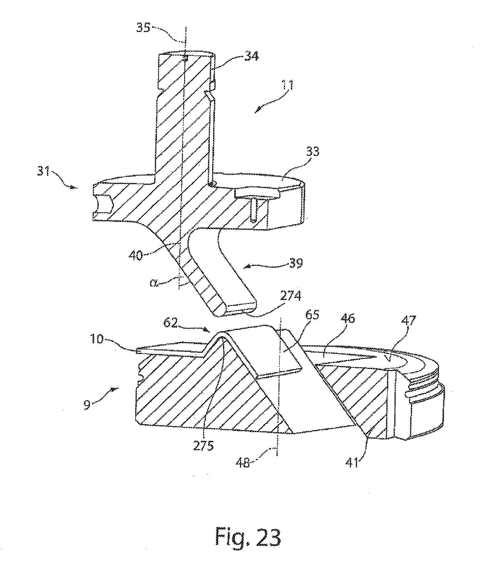
[0046] FIG. 23 shows a schematic side view of a further alternative embodiment of the tool for bending the workpiece.
DETAILED DESCRIPTION
[0047] FIG. 1 shows a machine tool 1 which is configured as a punch press. This machine tool 1 comprises a supporting structure with a closed machine frame 2. This comprises two horizontal frame limbs 3, 4 and two vertical frame limbs 5 and 6. The machine frame 2 surrounds a frame interior 7, which forms the working area of the machine tool 1 with an upper tool 11 and a lower tool 9.
[0048] The machine tool 1 is used to process planar workpieces 10, which for the sake of simplicity have not been shown in FIG. 1 and can be arranged in the frame interior 7 for processing purposes. A workpiece 10 to be processed is placed on a workpiece support 8 provided in the frame interior 7. The lower tool 9, for example in the form of a die, is mounted in a recess in the workpiece support 8 on the lower horizontal frame limb 4 of the machine frame 2. This die can be provided with a die opening. In the case of a punching operation the upper tool 11 formed as a punch dips into the die opening of the lower tool formed as a die.
[0049] The upper tool 11 and lower tool 9, instead of being formed by a punch and a die for punching, can also be formed by a bending punch and a bending die for shaping workpieces 10.
[0050] The upper tool 11 is fixed in a tool receptacle on a lower end of a ram 12. The ram 12 is part of a stroke drive device 13, by means of which the upper tool 11 can be moved in a stroke direction along a stroke axis 14. The stroke axis 14 runs in the direction of the Z axis of the coordinate system of a numerical controller 15 of the machine tool 1 indicated in FIG. 1. The stroke drive device 13 can be moved perpendicular to the stroke axis 14 along a positioning axis 16 in the direction of the double-headed arrow. The positioning axis 16 runs in the direction of the Y direction of the coordinate system of the numerical controller 15. The stroke drive device 13 receiving the upper tool 11 is moved along the positioning axis 16 by means of a motor drive 17.
[0051] The movement of the ram 12 along the stroke axis 14 and the positioning of the stroke drive device 13 along the positioning axis 16 are achieved by means of a motor drive 17, which can be configured in the form of a drive assembly 17, in particular a spindle drive assembly, with a drive spindle 18 running in the direction of the positioning axis 16 and fixedly connected to the machine frame 2. The stroke drive device 13, in the event of movements along the positioning axis 16, is guided on two three guide rails 19 of the upper frame limb 3, of which guide rails 19 can be seen in FIG. 1. The other guide rail 19 runs parallel to the visible guide rail 19 and is distanced therefrom in the direction of the X axis of the coordinate system of the numerical controller 15. Guide shoes 20 of the stroke drive device 13 run on the guide rails 19. The mutual engagement of the guide rail 19 and the guide shoe 20 is such that this connection between the guide rails 19 and the guide shoes 20 can also bear a load acting in the vertical direction. The stroke device 13 is mounted on the machine frame 2 accordingly via the guide shoes 20 and the guide rails 19. A further component of the stroke drive device 13 is a wedge gear 21, by means of which the position of the upper tool 11 relative to the lower tool 9 is adjustable.
[0052] The lower tool 9 is received moveably along a lower positioning axis 25. This lower positioning axis 25 runs in the direction of the Y axis of the coordinate system of the numerical controller 15. The lower positioning axis 25 is preferably oriented parallel to the upper positioning axis 16. The lower tool 9 can be moved directly on the lower positioning axis 16 by means of a motor drive assembly 26 along the positioning axis 25. Alternatively or additionally the lower tool 9 can also be provided on a stroke drive device 27, which is moveable along the lower positioning axis 25 by means of the motor drive assembly 26. This drive assembly 26 is preferably configured as a spindle drive assembly. The lower stroke drive device 27 can correspond in respect of its structure to the upper stroke drive device 13. The motor drive assembly 26 likewise may correspond to the motor drive assembly 17.
[0053] The lower stroke drive device 27 is likewise mounted displaceably on guide rails 19 associated with a lower horizontal frame limb 4. Guide shoes 20 of the stroke drive device 27 run on the guide rails 19, such that the connection between the guide rails 19 and guide shoes 20 at the lower tool 9 can also bear a load acting in the vertical direction. Accordingly, the stroke drive device 27 is also mounted on the machine frame 2 via the guide shoe 20 and the guide rails 19, moreover at a distance from the guide rails 19 and guide shoes 20 of the upper stroke drive device 13. The stroke drive device 27 may also comprise a wedge gear 21, by means of which the position or height of the lower tool 9 along the Z axis is adjustable.
[0054] By means of the numerical controller 15, both the motor drives 17 for a traversing movement of the upper tool 11 along the upper positioning axis 16 and the one or more motor drives 26 for a traversing movement of the lower tool 9 along the lower positioning axis 25 can be controlled independently of one another. The upper and lower tool 11, 9 are thus moveable synchronously in the direction of the Y axis of the coordinate system. An independent traversing movement of the upper and lower tool 11, 9 in different directions can also be controlled. This independent traversing movement of the upper and lower tool 11, 9 can be controlled simultaneously. As a result of the decoupling of the traversing movement between the upper tool 11 and the lower tool 9, an increased versatility of the processing of workpieces 10 can be attained. The upper and lower tool can also be configured to process the workpieces 10 in many ways.
[0055] One component of the stroke drive device 13 is the wedge gear 21, which is shown in FIG. 2. The wedge gear 21 comprises two drive-side wedge gear elements 122, 123, and two output-side wedge gear elements 124, 125. The latter are combined structurally to form a unit in the form of an output-side double wedge 126. The ram 12 is mounted on the output-side double wedge 126 so as to be rotatable about the stroke axis 14. A motor rotary drive device 128 is accommodated in the output-side double wedge 126 and advances the ram 12 about the stroke axis 14 as necessary. Here, both a left-handed and a right-handed rotation of the ram 12 in accordance with the double-headed arrow in FIG. 2 is possible. A ram mounting 129 is shown schematically. On the one hand, the ram mounting 129 allows low-friction rotary movements of the ram 12 about the stroke axis 14, and on the other hand the ram mounting 129 supports the ram 12 in the axial direction and accordingly dissipates loads that act on the ram 12 in the direction of the stroke axis 14 in the output-side double wedge 126.
[0056] The output-side double wedge 126 is defined by a wedge surface 130, and by a wedge surface 131 of the output-side gear element 125. Wedge surfaces 132, 133 of the drive-side wedge gear elements 122, 123 are arranged opposite the wedge surfaces 130, 131 of the output-side wedge gear elements 124, 125. By means of longitudinal guides 134, 135, the drive-side wedge gear element 122 and the output-side wedge gear element 124, and also the drive-side wedge gear element 123 and the output-side wedge gear element 125, are guided moveably relative to one another in the direction of the Y axis, that is to say in the direction of the positioning axis 16 of the stroke drive device 13.
[0057] The drive-side wedge gear element 122 has a motor drive unit 138, and the drive-side wedge gear element 123 has a motor drive unit 139. Both drive units 138, 139 together form the spindle drive assembly 17.
[0058] The drive spindle 18 shown in FIG. 1 is common to the motor drive units 138, 139 and is configured in the form of a drive device that is mounted on the machine frame 2 and consequently on the supporting structure.
[0059] The drive-side wedge gear elements 122, 123 are operated by the motor drive units 138, 139 in such a way that said wedge gear elements move, for example, towards one another along the positioning axis 16, whereby a relative movement is performed between the drive-side wedge gear elements 122, 123 on the one hand and the output-side wedge gear elements 124, 125 on the other hand. As a result of this relative movement, the output-side double wedge 126 and the ram 12 mounted thereon is moved downwardly along the stroke axis 14. The punch 11 mounted for example on the ram 12 performs a working stroke and in so doing processes a workpiece 10 mounted on the workpiece rest 28, 29 or the workpiece support 8. By means of an opposite movement of the drive wedge elements 122, 123, the ram 12 is in turn raised or moved upwardly along the stroke axis 14.
[0060] The above-described stroke drive device 13 according to FIG. 2 is preferably of the same design as the lower stroke drive device 27 and receives the lower tool 9.
[0061] FIG. 3 shows a schematic graph of a possible stroke movement of the ram 12. The graph shows a stroke profile along the Y axis and the Z axis. By means of a superposed control of a traversing movement of the ram 12 along the stroke axis 14 and along the positioning axis 16, an obliquely running stroke movement of the stroke ram 12 downwardly towards the workpiece 10 can, for example, be controlled, as shown by the first straight line A. Once the stroke has been performed, the ram 12 can then be lifted vertically, for example, as illustrated by the straight line B. For example, an exclusive traversing movement along the Y axis is then performed in accordance with the straight line C, in order to position the ram 12 for a new working position relative to the workpiece 10. For example, the previously described working sequence can then be repeated. If the workpiece 10 is moved on the workpiece rest surface 28, 29 for a subsequent processing step, a traversing movement along the straight line C may also be spared.
[0062] The possible stroke movement of the ram 12 on the upper tool 11 shown in the graph in FIG. 3 is preferably combined with a lower tool 9 that is held stationary. Here, the lower tool 9 is positioned within the machine frame 2 in such a way that, at the end of a working stroke of the upper tool 11, the upper and lower tool 11, 9 assume a defined position.
[0063] This exemplary, superposed stroke profile can be controlled both for the upper tool 11 and the lower tool 9. Depending on the processing of the workpiece 10 that is to be performed, a superposed stroke movement of the upper tool and/or lower tool 9 can be controlled.
[0064] FIG. 4 shows a schematic graph illustrating a stroke movement of the ram 12 in accordance with the line D, shown by way of example, along a Y axis and a Z axis. In contrast to FIG. 3, it is provided in this exemplary embodiment that a stroke movement of the ram 12 can pass through a curve profile or arc profile by controlling a superposition of the traversing movements in the Y direction and Z direction appropriately by the controller 15. By means of a versatile superposition of this kind of the traversing movements in the X direction and Z direction, specific processing tasks can be performed. The control of a curve profile of this kind can be provided both for the upper tool 11 and/or lower tool 9.
[0065] FIG. 5 shows a schematic view of the machine tool 1 according to FIG. 1. Workpiece rests 28, 29 extend laterally in one direction each on the machine frame 2 of the machine tool 1. The workpiece rest 28 can, for example, be associated with a loading station (not shown in greater detail), by means of which unprocessed workpieces 10 are placed on the workpiece rest surface 28. A feed device 22 is provided adjacently to the workpiece rest surface 28, 29 and comprises a plurality of grippers 23, in order to grip the workpiece 10 placed on the workpiece rest 28. The workpiece 10 is guided through the machine frame 2 in the X direction by means of the feed device 22. The feed device 22 may also preferably be controlled so as to be moveable in the Y direction. A free traversing movement of the workpiece 10 in the X-Y plane may thus be provided. Depending on the work task, the workpiece 10 may be moveable by the feed device 22 both in the X direction and against the X direction. This movement of the workpiece 10 can be adapted to a movement of the upper tool 11 and lower tool 9 in and against the Y direction for the processing work task at hand.
[0066] The further workpiece rest 29 is provided on the machine frame 2 opposite the workpiece rest 28. This further workpiece rest can be associated, for example, with an unloading station. Alternatively, the loading of the unprocessed workpiece 10 and unloading of the processed workpiece 10 having workpieces 81 can also be associated with the same workpiece rest 28, 29.
[0067] The machine tool 1 may furthermore comprise a laser processing device 201, in particular a laser cutting machine, which is shown merely schematically in a plan view in FIG. 5. This laser processing device 201 may be configured, for example, as a CO2 laser cutting machine. The laser processing device 201 comprises a laser source 202, which generates a laser beam 203, which is guided by means of a beam guide 204 (shown schematically) to a laser processing head, in particular laser cutting head 206, and is focused therein. The laser beam 204 is then oriented perpendicularly to the surface of the workpiece 10 by a cutting nozzle, in order to process the workpiece 10. The laser beam 203 acts on the workpiece 10 at the processing location, in particular cutting location, preferably jointly with a process gas beam. The cutting point, at which the laser beam 203 impinges on the workpiece 10, is adjacent to the processing point of the upper tool 11 and lower tool 9.
[0068] The laser cutting head 206 is moveable by a linear drive 207 having a linear axis system at least in the Y direction, preferably in the Y and Z direction. This linear axis system, which receives the laser cutting head 206, can be associated with the machine frame 2, fixed thereto or integrated therein. A beam passage opening 210 is provided in the workpiece rest 28, below a working space of the laser cutting head 206. A beam capture device for the laser beam 21 may be provided preferably beneath the beam passage opening 210. The beam passage opening 210 and as applicable the beam capture device can also be configured as one unit.
[0069] The laser processing device 201 may alternatively also comprise a solid-state laser as laser source 202, the radiation of which is guided to the laser cutting head 206 with the aid of a fibre-optic cable.
[0070] The workpiece rest 28, 29 can extend until directly at the workpiece support 8, which at least partially surrounds the lower tool 9. Within a resultant free space created therebetween, the lower tool 9 is moveable along the lower positioning axis 25 in and against the Y direction.
[0071] For example, a processed workpiece 10 lies on the workpiece rest 28 and has a workpiece part 81 cut free by a cutting gap 83, for example by punching or by laser beam processing, apart from a remaining connection 82. The workpiece 81 is held in the workpiece 10 or the remaining sheet skeleton by means of this remaining connection. In order to separate the workpiece part 81 from the workpiece 10, the workpiece 10 is positioned by means of the feed device 22 relative to the upper and lower tool 11, 9 for a separation and discharge step. Here, the remaining connection 82 is separated by a punching stroke of the upper tool 11 relative to the lower tool 9. The workpiece part 81 can, for example, be discharged downwardly by partially lowering of the workpiece support 8. Alternatively, in the case of larger workpiece parts 81, the cut-free workpiece part 81 can be transferred back again to the workpiece rest 28 or onto the workpiece rest 29 in order to unload the workpiece part 81 and the sheet skeleton. Small workpiece parts 81 may also be discharged optionally through an opening in the lower tool 9.
[0072] FIG. 6 shows a schematic side view of a first embodiment of a tool 31. FIG. 7 shows a perspective view of the tool 31 according to FIG. 6. The tool 31 is formed as a punching tool and comprises a punch 11, which forms the upper tool, and a die 9, which forms the lower tool. The punch 11 has a main body 33 with a clamping shaft 34 and an adjustment or indexing element or an adjustment or indexing wedge 36. The clamping shaft 34 is used to fix the punch 11 in the machine-side upper tool receptacle. Here, the orientation of the punch 11 and/or the rotary position of the punch 11 are/is determined by the indexing wedge 36. The punch 11 is rotated here about a positioning axis 35. This positioning axis 35 forms a longitudinal axis of the clamping shaft 34 and preferably also a longitudinal axis of the main body 33. As a result of the punch 11 assuming the rotary position in the upper tool receptacle, a processing tool 37, which is shown as a cutting tool in the exemplary embodiment, is oriented relative to the die 9. The die 9 likewise comprises a main body 41, which is suitable to be fixed in a defined rotary position in the machine-side lower tool receptacle, for example by at least one indexing element 42. The die 9 is rotatable about a positioning axis 48. This forms a longitudinal axis or longitudinal centre axis of the main body 41. A stripper or holding-down device (not shown in greater detail) can be provided between the punch 11 and the die 9.
[0073] The die 9 has an opening 46 in the main body 41, which opening is preferably delimited by a peripheral rest surface 47. This opening 46 preferably penetrates fully through the main body 41, such that workpiece parts 81 cut off or cut free can be discharged through this opening 46.
[0074] The processing tool 37 on the punch 11 comprises a tool body 39, at the free end of which there is provided a cutting edge 38. This cutting edge 38 may be peripheral. Alternatively, the cutting edge 38 may also be formed only in the region of a cutting surface 56. A longitudinal axis 40 of the tool body 39 is inclined by an angle .alpha. relative to the positioning axis 35. The longitudinal axis 40 of the tool body 39 lies outside the positioning axis 35. In the exemplary embodiment the tool body 39 is formed as an elongate rectangular body. A punch surface 43 is provided at the free end of the tool body 49 and is delimited by the cutting edge 38. The punch surface 43 is preferably oriented at a right angle to the longitudinal axis 40 of the tool body 39. Alternatively, it may be provided that instead of the elongate, rectangular tool body 39, a tool body 39 with a contour that is square, round, elliptical or otherwise shaped is provided, wherein, regardless of the shape of the tool body, a longitudinal axis 40 is oriented at an incline to the positioning axis 35.
[0075] The die 9 comprises in the opening 46, preferably adjacently to the rest surface 37, an inner counter cutting edge 51. This inner counter cutting edge 51 is provided on a support surface 61, which protrudes relative to the rest surface 47 and is inclined at an angle that corresponds to the angle of the punch surface 43. A cutting surface 56 adjoining the inner counter edge 51 may be formed advantageously parallel to the longitudinal axis 40 of the tool body 39, or is perpendicular to the support surface 61. The cutting surface 56 is preferably inclined relative to a perpendicular to the support surface 61, for example by 1.degree. to 2.degree., such that the cutting surface 55 is oriented at an angle of less than 90.degree. to the support surface 61. This cutting surface 56 corresponds to a wall forming the outer side of the tool body 39, starting from the cutting edge 38.
[0076] By means of this tool 31 it is now possible that, on a processed workpiece 10 with a bent portion 62 formed therein, a right-angled cutting edge can be provided in the region of the bent portion 62 when a raised remaining part is cut off from a processed workpiece 10. The support surface 61 is oriented relative to the rest surface 47 at an angle corresponding to the angle of the bent portion relative to the workpiece plane of the workpiece 10. The longitudinal axis 40 of the tool body 39 on the punch 11 is in turn oriented normal to the bent portion 62.
[0077] A linear stroke movement along an inclined axis can be controlled by means of the independent control of the upper tool 11 and the lower tool 9 in the machine tool 1 along their positioning axes 16, 25 and by means of a mutually independent control of a stroke movement along the stroke axis 14, 30. An arbitrary curved stroke movement or an arcuate stroke movement can also be controlled. In the case of the present tool 31 according to FIGS. 6 and 7 the die 9, for example, can be controlled to be stationary in the machine tool 1 during a working step, whereas the punch 11 is controlled with a stroke movement along an inclined axis. This inclined axis corresponds to the longitudinal axis 40 of the tool body 39. A right-angled part edge can thus be produced at the bent portion 62.
[0078] FIG. 8 shows a side view of an alternative embodiment of the tool 31 as compared to FIG. 4. FIG. 9 shows a perspective view of the tool 31 according to FIG. 8. In this embodiment the punch 11 corresponds to the embodiment according to FIGS. 6 and 7.
[0079] The die 9 deviates in respect of the embodiment of the inner counter cutting edge 51 from the embodiment in FIGS. 6 and 7. The inner counter cutting edge 31 is for example positioned flush with the rest surface 37. The inner counter edge 51 is adjoined by a cutting surface 56, which is oriented parallel to the longitudinal axis 40 of the tool body 39.
[0080] A slanted punching stroke is in turn made possible by this tool 31. Here, a slanted part edge is produced on a flat workpiece 10. In order to attain a slanted part edge, the tool 31 is controlled similarly to the previously described control of the tool 31 according to FIGS. 4 and 5. The angular position of the longitudinal axis 40 of the tool body 39 and accordingly the orientation of the cutting surface 56 determines the angular position of the end side of the workpiece 10 or workpiece part 81.
[0081] FIG. 10 shows an alternative embodiment of the tool 31 as compared to FIG. 6. FIG. 11 shows a perspective view of the tool 31 according to FIG. 10 in a sectional view. In this tool 31 the punch 11 corresponds in respect of its tool body 39 to the embodiment according to FIG. 6. In this embodiment it is provided, for example, that the punch 11 is formed in two parts. The clamping shaft 34 and the tool body 39 are formed in one part and are preferably fastened to the main body 33 by a clamped connection. The die 9 is formed such that a counter cutting insert 50 is provided on the die 9. This counter cutting insert 50 can be provided, for example, exchangeably on the main body 41 of the die 9. This counter cutting insert 50 comprises at least one inner counter cutting edge 51, which is associated with the opening 46 in the main body 41 of the die 9. This counter cutting insert 50 is designed to form an upper chamfer 64 on the workpiece 10 in cooperation with the upper tool 11. This chamfer 64 is shown, for example, in the sectional illustration in FIG. 11.
[0082] The counter cutting insert 50 for this purpose has a U-shaped recess, which is delimited by an inner counter cutting edge 51, which for example is oriented perpendicularly to the rest surface 47 of the die. The distance of the counter cutting edges 51 is adapted to the width of the tool body 39 or the cutting edge 38. A defined length of the chamfer 64 can thus be made in one working stroke. The counter cutting insert 50 comprises a support surface 61 which is raised relative to the support surface 67. An end side of the workpiece 10 bears against this support surface 61.
[0083] For example, a 45.degree. chamfer can be formed by a stroke movement of the upper tool 11 which, for example, is controlled along the longitudinal axis 40 of the tool body 39. With the cutting edge 38 of the upper tool 11 resting against and acting on the workpiece 10, the workpiece is pressed against the support surface 61 at the counter cutting insert 50. Material is then sheared off by the punch surface 43 dipping, by means of the at least one cutting edge 38 arranged thereon, relative to the U-shaped opening, which is delimited by the counter cutting edges 51. The sheared-off material is discharged downwardly via the opening 46.
[0084] By means of a lateral displacement of the workpiece 10 in steps, a chamfer 64 can be formed over a larger region of the end side on the workpiece 10. This can be achieved for example by a traversing movement of the upper tool 11 and the lower tool 9 along the Y axis, if the end side of the workpiece 10 to be processed is oriented along the X axis, by the control of the feed device 22.
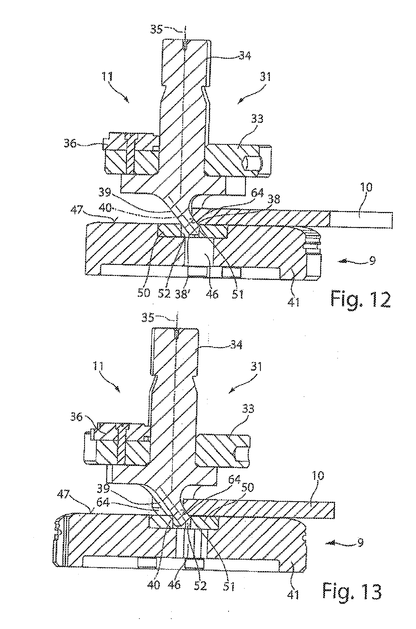
[0085] FIG. 12 shows a schematic sectional view of an alternative embodiment of the tool 31 in a working position. FIG. 13 shows the tool 31 according to FIG. 12 in a further perspective sectional view.
[0086] This tool 31 according to FIGS. 12 and 13 differs from the tool 31 according to FIGS. 10 and 11 in that the chamfer 64 is formed on an underside of the workpiece 10. The upper tool 11 corresponds to the embodiment according to the tool 31 in FIG. 10 or FIG. 6. The die 9, in contrast to the embodiment according to FIG. 10, has an alternative embodiment of the counter cutting insert 50. This counter cutting insert 50 is associated with the opening 46 in the main body 41 of the die 9. This counter cutting insert 50 likewise has a through-opening 52, into which the tool body 39 of the upper tool 11 can dip at least in part during a working stroke. The through-opening 52 of the counter cutting insert 50 is adapted to the geometry of the tool body 39, in particular the punch surface 43 and the at least one cutting edge 38 provided therein. An upper side of the counter cutting insert 50 is oriented flush with the rest surface 47 of the main body 41 of the die 9.
[0087] In order to form a chamfer 64 on a lower end edge of the workpiece 10, the workpiece is positioned relative to the through-opening 52 in such a way that, after a first stroke phase, a lower cutting edge 38 bears against a delimitation of the through-opening 52 and can be guided past it, whereas the cutting edge 38 acts on the end face of the workpiece 10. During a further stroke movement, the tool body 39 is supported at the through-opening 52 and the chamfer 64 is formed by the cutting edge 38. The workpiece 10 is supported on a counter cutting edge 51.
[0088] In order to hold down the workpiece 10 at the rest surface 47, a counter die (not shown in greater detail) or a holding-down device can be provided on the workpiece upper side of the workpiece 10 and is preferably formed in a planar manner.
[0089] The chamfer 64 may be a structural part of a workpiece 10 to be produced. A deburring of the workpiece 10 can also be performed. In addition, the forming of this chamfer 64 or flattened portion can also be a preparatory working step for forming a welding edge.
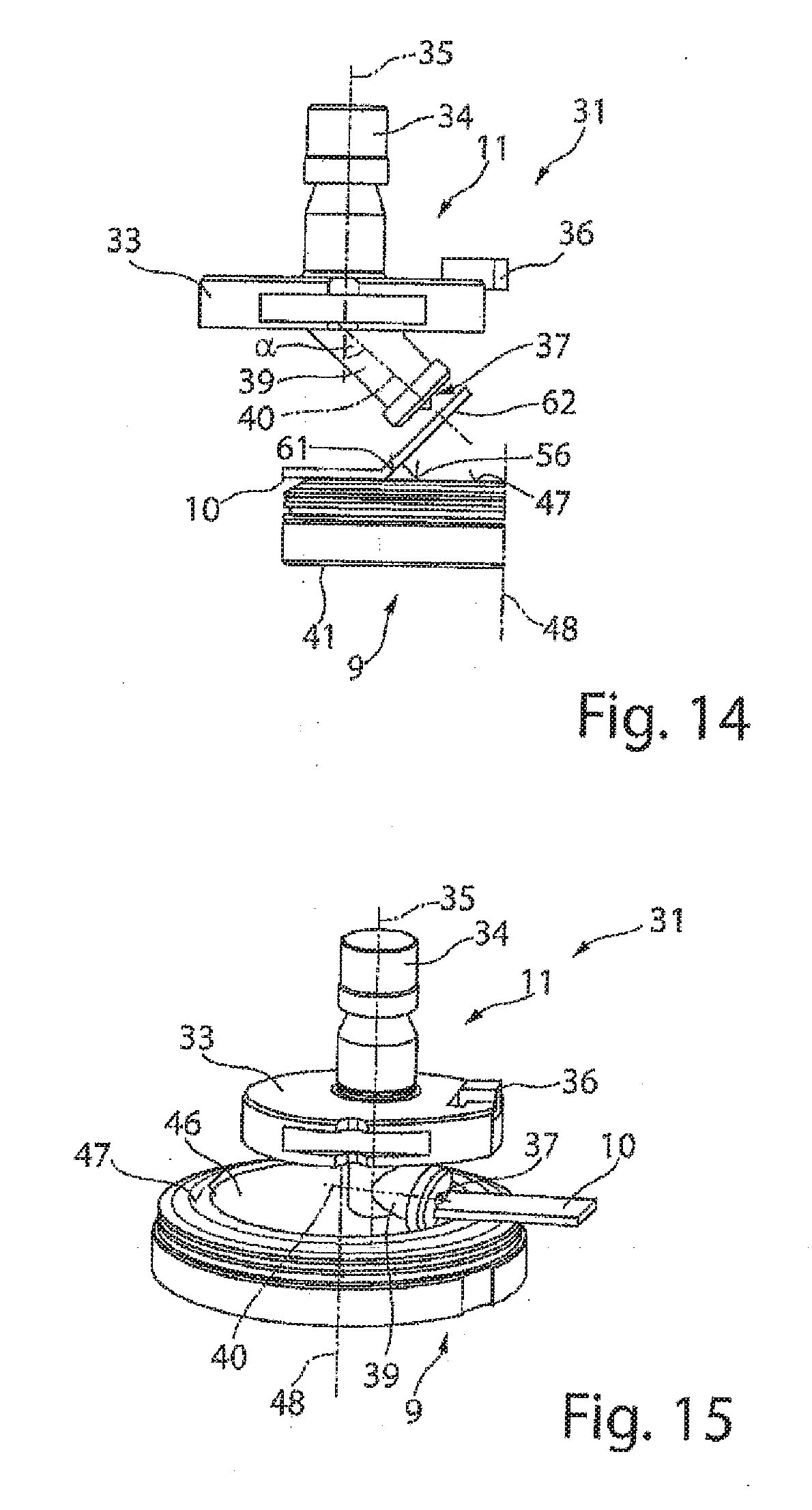
[0090] A schematic view of a further alternative embodiment of the tool 31 is shown in FIG. 14. In this embodiment the processing tool 37 is formed as a signing and/or engraving tool. The orientation of the longitudinal axis 40 of the tool body 39 is again oriented perpendicularly to the bent portion 62 on the workpiece 10. By means of the independent control of the upper tool 11 and lower tool 9 it is possible that a marking, lettering or the like can be made in the surface of the bent portion 62.
[0091] FIG. 15 shows an alternative embodiment of the tool 31 as compared to FIG. 14. In this embodiment it is provided that the longitudinal axis 40 of the tool body 39 is inclined more strongly relative to the positioning axis 35. For example, this inclination may comprise 90.degree. to the position axis 35. In an exemplary embodiment of this kind it is possible that an end side of the workpiece 10 or of a workpiece part 81 can be engraved and/or signed and/or processed.
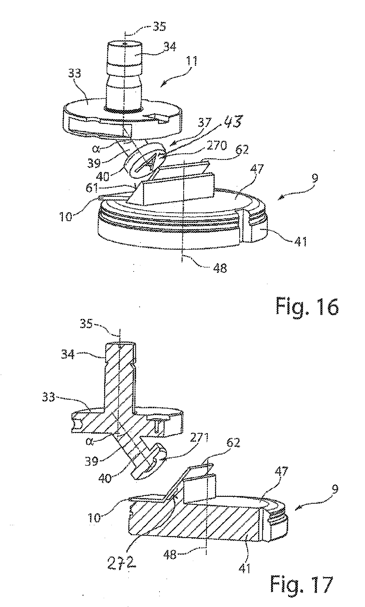
[0092] FIG. 16 shows a perspective view of an alternative tool 31 as compared to FIG. 14. In this embodiment it is provided that the processing tool 37 is formed as an embossing tool. For example, an embossing element 270 is provided on an end side of the tool body 39. This embossing element can be, for example, a letter, a number, a symbol or the like. In order to form this embossing the punch surface 43 of the tool body 39 is preferably oriented parallel to the surface of the bent portion 62, or at an incline to the support face 61.
[0093] FIG. 17 shows an alternative embodiment of the tool 31 as compared to FIG. 16. The processing tool 37 is formed as a shaping tool. For example, a shaping element 271 is provided on the punch surface 43 of the inclined tool body 39, by means of which shaping element a shaping contour can be formed in a bent portion 62 on the workpiece 10. A counter shaping element 272 is shown in the support surface 61 and corresponds to the shaping element 271 in respect of the profile of the contour. For example, a cup-shaped indentation can be formed in the bent portion 62 by means of this processing tool 37, since the shaping element 271 is formed as a frustoconical elevation and the counter shaping element 272 is formed in a manner complementary thereto. Alternatively, an elongate bead, V-bead or other contours can also be formed in the bent portion 62. It can also be provided that, instead of forming a shaping in the bent portion, a punch is provided, which formed an aperture or recess in the bent portion 62. This recess can have many types of contour and may have different geometries. Also, instead of the shaping element 271, a punching and bending element can be provided in order to form, for example, a gill in the bent portion 62. The tool body 39 or the processing and/or cutting tools arranged specifically on the punch surface 43 of the inclined tool body 39 can be provided in a wide range of embodiments.
[0094] FIG. 18 shows a perspective view of an alternative embodiment of the tool 31 as compared to FIG. 6. In the case of this tool 31 a tool body 39 inclined relative to the positioning axis 48 along the longitudinal axis 40 is also provided. The processing tool 37 is formed as a pivoting and bending tool. To this end, the tool body 39, at its end-side end, has a punch surface 43, which has a curved or rounded contour or a radius of curvature, so as to form a bending edge 274.
[0095] The lower tool 9 again comprises a main body 41 with a rest surface 47, which surrounds an opening 46. The opening 46 is delimited by a counter bending edge 275 formed on the lower tool 9. The counter bending edge 275 is preferably of the same length as, or longer than the bending edge 274 on the upper tool 11. Depending on the contour, the thickness and/or the course of the counter bending edge 275, the bent portion 62 can be pivoted and shaped relative to the workpiece 10, from the plane thereof. In the exemplary embodiment the counter bending edge 275 is formed as a thin plate in the form of a circle segment. A bent portion 62 can thus be bent at an angle of more than 90.degree. to the workpiece plane of the workpiece 10. This will be described in greater detail hereinafter with reference to FIGS. 19 to 22.
[0096] FIG. 19 shows a schematic sectional view of the tool 31 according to FIG. 18 in a first working position. The workpiece 10 is resting on the lower tool 9, on the rest surface 47. A U-shaped tab that has been cut free and which is to be shaped to form the bent portion 62, lies above the opening 46 in the lower tool 9. In a first working step the upper tool 11 is moved along the stroke axis 14 or the positioning axis 35 towards the lower tool 9, until the bending edge 274 comes to bear against the workpiece 10. In so doing, the bending edge 274 is moved inwardly in the direction of the opening 46 relative to the counter bending edge 275. By means of a further stroke movement of the upper tool 11 into the opening 46 in the lower tool 9, a first shaping of the bent portion 62 is performed, as shown in FIG. 20.
[0097] With increasing stroke movement of the upper tool 11 relative to the lower tool 9, the bent portion 62 is bent through 90.degree., as is shown in FIG. 21. As soon as the upper tool 11 is now moved in a further working step along the upper positioning axis 16 in the direction of the counter bending edge 275, the bent portion 62 is bent further, such that an angle between the workpiece 10 and the bent portion 62 of less than 90.degree. can be formed.
[0098] A bending radius between the workpiece 10 and the bent portion 62 is dependent on the distance between the bending edge 274 and the counter bending edge 275. The shorter is the distance, the smaller is the radius of curvature.
[0099] FIG. 23 shows a further alternative embodiment of a tool 31 as compared to FIG. 6. In this embodiment it is provided that, starting from a produced bent portion 62 at an angle to the workpiece 10, as is shown in FIGS. 6 and 7, a tool 31 according to FIG. 23 is used, in which the processing tool 37 is formed as a shaping tool. The tool body 39, at its front end, again has a bending edge 274. The design of the upper tool 11 can correspond to the embodiment according to FIG. 18.
[0100] The lower tool 9 comprises a support surface 61, which is elevated and inclined relative to the rest surface 47, and a cutting surface 56. A counter bending edge 275 is provided between the support surface 61 and the cutting surface 56. The first bent portion 62 can be bent again by a linear stroke movement inclined relative to the positioning axis 35, in particular along the inclined longitudinal axis 40, such that a second bent portion 65 is then formed, which is preferably oriented in a direction opposite the bent portion 62. Following the linear stroke movement of the upper tool 11 relative to the lower tool 9 along the longitudinal axis 40 or parallel to the cutting surface 56, the upper tool 11 can be raised.
* * * * *
D00000
D00001
D00002
D00003
D00004
D00005
D00006
D00007
D00008
D00009
D00010
D00011
D00012
XML
uspto.report is an independent third-party trademark research tool that is not affiliated, endorsed, or sponsored by the United States Patent and Trademark Office (USPTO) or any other governmental organization. The information provided by uspto.report is based on publicly available data at the time of writing and is intended for informational purposes only.
While we strive to provide accurate and up-to-date information, we do not guarantee the accuracy, completeness, reliability, or suitability of the information displayed on this site. The use of this site is at your own risk. Any reliance you place on such information is therefore strictly at your own risk.
All official trademark data, including owner information, should be verified by visiting the official USPTO website at www.uspto.gov. This site is not intended to replace professional legal advice and should not be used as a substitute for consulting with a legal professional who is knowledgeable about trademark law.